

Page 1

PN 047-0176 REV02
ECF – SERIES
Installation and Operation Manual
Controlled Ferro-Resonant
Sales – Service – Recycling
Toll Free: U.S.A. 1-888-563-6300
Canada 1-800-268-2698
(GB4128 2009-04)
Ferro Magnetics Corporation, St. Louis, MO
Page 2

INDEX
PAGE SECTION DESCRIPTION
3 - SAFETY INSTRUCTIONS
4 1.0 INSTALLATION
4 1.1 RECEIVING
4 1.2 LOCATION
5 1.3 LINE VOLTAGE ADJUSTMENTS
6 1.4 AC SERVICE REQUIREMENTS
6 1.5 CONNECTING AC SERVICE TO CHARGER
6 1.6 GROUNDING THE CHARGER
6 1.7 BATTERY CONNECTOR AND CHARGING CABLE
6 1.8 CHARGING RATE ADJUSTMENT
7 2.0 OPERATION
7 2.1 046-0172 CONTROL
7 2.1.1
8 2.1.2
9 2.1.3
10 2.1.4
10 2.1.5
10 2.1.6
10 2.1.7
11 2.1.8
12 2.1.9
12 2.1.10
14 3.0 OPTIONAL FEATURES
14 3.1 FUSIBLE DOOR-INTERLOCK SWITCH (JIC SWITCH)
14 3.2 REMOTE CONTROL
14 3.3 STACKING OF TWO CABINETS (MAXIMUM)
15 4.0 TROUBLESHOOTING & GENERAL MAINTENANCE
15 4.1 SYMPTOMS AND POSSIBLE CAUSES
15 4.2 GENERAL MAINTENANCE
16 5.0 REPLACEABLE PARTS
16 5.1 ORDERING INFORMATION
16 5.2 RECOMMENDED SPARES
17 5.3 SPARE PARTS LIST
18 - SCHEMATIC
FEATURE SUMMARY
NORMAL DAILY CHARGE
EQUALIZE CHARGE
TIME OF DAY START
SETTING TIME OF DAY
EMERGENCY STOP
SETTING BATTERY COOL DOWN TIME
CHARGE INDICATIONS
F3 (LOW BATTERY) OVERRIDE
DISPLAYING ADDITIONAL CHARGE INFORMATION
Ferro Magnetics Corporation, St. Louis, MO
Page 3

SAFETY INSTRUCTIONS
WARNING
THIS EQUIPMENT CONTAINS LETHAL VOLTAGE LEVELS. INSTALLATION AND
SERVICING MUST BE PERFORMED BY QUALIFIED PERSONNEL
IMPORTANT: SAVE THESE INSTRUCTIONS!
READ AND FOLLOW ALL INSTRUCTIONS BEFORE INSTALLING, OPERATING, OR
SERVICING CHARGER. ANY DEVIATION CAN CAUSE SERIOUS AND PERMANENT
DAMAGE. FAILURE TO FOLLOW THE INSTRUCTIONS VOIDS THE WARRANTY.
1. Install and ground the charger in accordance with the National Electric Code and your local
electric code. Failure to properly ground the charger could result in a fatal electric shock.
2. To reduce the risk of fire, install chargers on a surface of non-combustible material, such as
concrete, stone, brick or grounded metal.
3. Connect only batteries of the same number of cells and ampere-hour rating as listed on the
charger nameplate. Damage to the battery could occur, particularly if the battery has fewer cells
than the rating of the charger.
4. Do not touch uninsulated parts of the output connector or battery terminals. A possibility of
serious electrical shock exists.
5. During charge, batteries produce hydrogen gas, which can explode if ignited. Never smoke, use
an open flame, or create sparks in the vicinity of the battery. Ventilate well when the battery is in
an enclosed space.
6. Do not connect or disconnect the battery plug while the charger is on. Doing so will cause
arching and burning of the connector resulting in charger damage or battery explosion.
7. Lead-acid batteries contain sulfuric acid, which is caustic and can cause chemical burns to the
skin. Refer to the battery manufacturers instructions for safe handling of batteries. Use proper
personnel protective equipment. Do not get in eyes, on skin, or on clothing. In cases of contact
with eyes, flush immediately with clean water for 15 minutes. Seek medical attention
immediately.
8. Do not operate the charger with the door open or with any panels removed. De-energize all AC
and DC power connections before servicing the charger.
9. The charger is not for outdoor use. Do not expose the charger to water spray, rain or snow.
10. Do not operate the charger with damaged cables, including cables with exposed conductors or
damaged connectors. Replace damaged cables before operation.
11. Do not operate the charger if it has been dropped, received a sharp blow, or otherwise damaged
in any way. Call your service representative.
Ferro Magnetics Corporation, St. Louis, MO
Page 4

1. INSTALLATION
1.1. RECEIVING
Immediately upon receipt of the charger, check it against the shipping invoice to ensure the shipment is
complete and undamaged.
Examine the outsid e of the packing for signs of rou gh handli ng before accepting the cha rger from the
carrier. If there is evid ence of damag e, the recei pt sho uld be signed, an d b oth copi es (carrier's an d
receiving copies) marked "Shipment Received Damaged". The carri er's representative should be called
immediately and asked to make a "Carrier's Damage Report". If concealed damage is later detected, the
carrier should be calle d and requested to make a "Carrie r's Inspection for Concealed Damage Report".
After inspection by the carrier, arrangements should be made with the charger representative to have the
charger repaired before placing it in service. When contacting your charger representative for assistance
on a damage claim or shi pment error, provide the Model , and S erial Number of the charger, and a full
description of the damage or error. It i s good practice to move the charger to the installation site before
uncrating. When using bars, hammers, etc. for uncrating, use care to avoid damage to the charger
WARNING: To reduce the risk of fire, install the battery charger on a non-combustible surface
such as concrete, stone, brick, or steel. DO NOT operate the charger on its shipping skid
materials.
1.2. LOCATION
For the best operating conditions and longest life, take care in selecting an installation site. Avoid
locations exposed to high humidity, temperature extremes or dust. Moisture condensing on machine parts
and electrical components can cause corrosion, which seriously affects operation, efficiency and life. All
units are designed for floor mounting. Standard cases may be stack-mounted if required, up to 2 high. If
so, optional stacking brackets are required and available as an option. See section 3.0 for more details.
Dust and dirt will also decrease heat radiation from heat-generating components, such as transformers
and diodes. This will result in higher operating temperatures and shorter life. Adequate air circulation is
needed at all times in order to ensure proper operation. Provide a minimum of 6 inches of free air space
at the sides and rear of the charger. The front of the charger must remain unobstructed for serviceability.
.
Ferro Magnetics Corporation, St. Louis, MO
Page 5
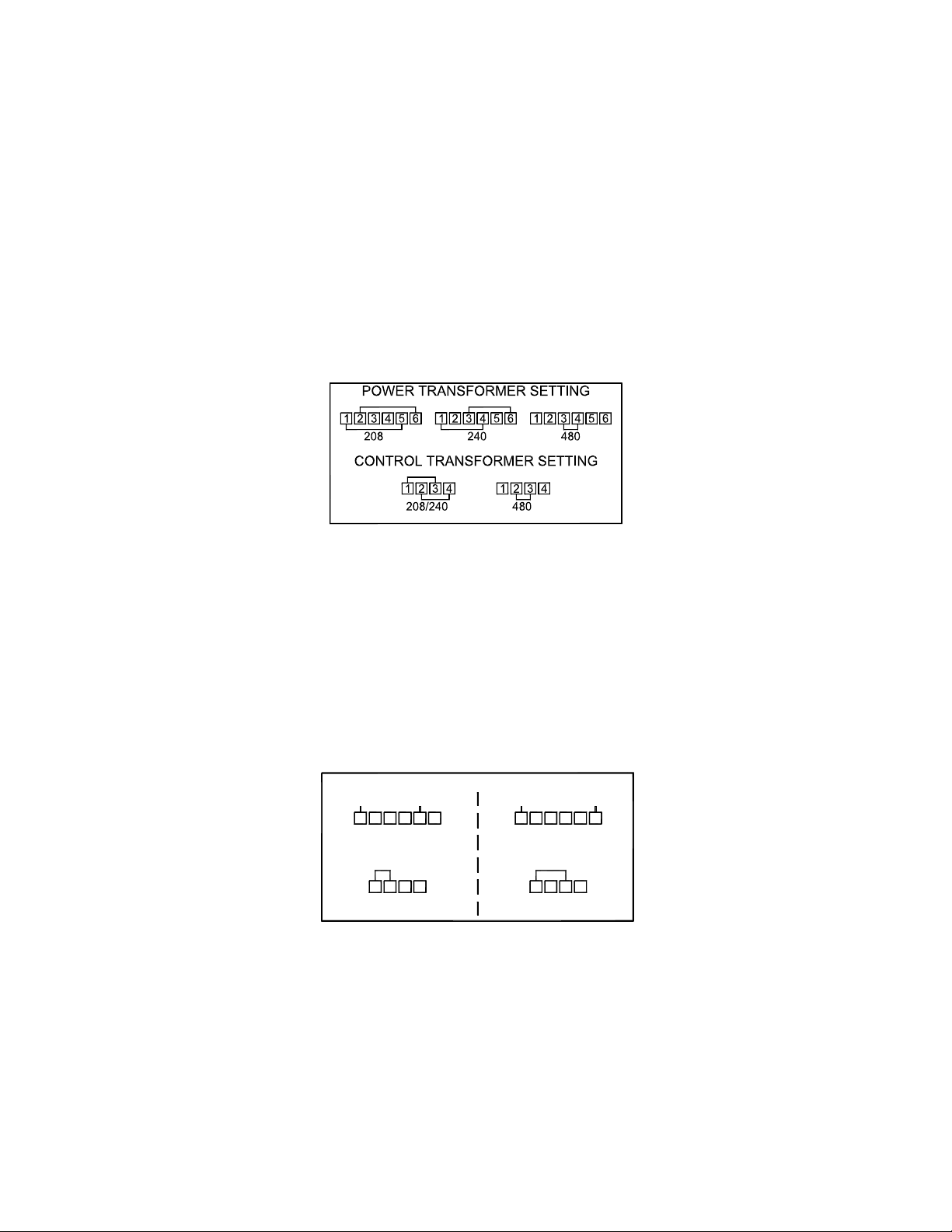
1.3. LINE VOLTAGE ADJUSTMENTS
All chargers are shipped with the AC line voltage ju mper wires set for the AC voltage spe cified on the
purchase order. Before connecting the charger to the AC service, it should be verified that the internal AC
voltage connections match the available AC service voltage. If necessary, change the AC voltage jumper
wires as shown in Figs. 1.3.1 through 1.3.2.
CAUTION: It will be necessary in most cases to change the AC fuses when the AC voltage
jumpers are changed. Refer to the fuse chart on the inside door of the charger for the correct fuse
rating.
A.C. Voltage Adjustments
1Ø & 3Ø 60Hz. (208/240/480)
A.C. Voltage Adjustments
POWER TRANSFORMER SETTING
L1 L1
1234
480
1234 132 4
CONTROL
TRANSFORMER
Fig. 1.3.1.
“B” Voltage Code
Fig.1.3.2.
3 Ø 60Hz. (480/575)
“K” Voltage Code
L2 L2
56
1234
CONTROL
TRANSFORMER
56
575
Ferro Magnetics Corporation, St. Louis, MO
Page 6

1.4. AC SERVICE REQUIREMENTS
Follow local code requirements if they are different than the in structions i n this man ual. After ch ecking
the transformer connections as d escribed in Parag raph 1.3, refer to Table 1-1, to determine the corre ct
ratings for the AC cable, AC fuses, and AC service disconnect switch for the line amperes as listed on the
nameplate of the charger for the available AC voltage
Line Amperes Disconnect Switch Fuse Size Amps
000.0 - 02.5 30A 05
003.0 - 04.5 30A 07
005.0 - 07.5 30A 10
008.0 - 11.0 30A 15
011.5 - 15.5 30A 20
016.0 - 18.0 30A 25
018.5 - 22.0 30A 30
022.5 - 27.0 60A 35
027.5 - 32.0 60A 40
032.5 - 40.0 60A 50
040.5 - 48.0 60A 60
048.5 - 64.0 80A 80
065.0 - 80.0 100A 100
081.0 - 95.0 125A 125
096.0 - 125.0 150A 150
TABLE 1-1
For voltages up to 240, use a 240 volt disconnect switch.
For voltages greater than 240 to 600, use a 600 volt disconnect switch.
• Two conductors and ground wire required for single phase.
• Three conductors and ground wire required for three-phase
1.5. CONNECTING AC SERVICE TO THE CHARGER
1.5.1. SINGLE-PHASE MODELS
Connect the AC service to the L1 and L2 terminals located at the end of the AC fuse block.
Note: If the charger has been ordered with an AC input door-mounted disconnect switch, the AC input
wires will be connected to the L1 and L3 terminals at the top of the switch body.
1.5.2. THREE-PHASE MODELS
Connect the AC service to the L1, L2 and L3 terminals located at the end of the AC fuse block.
Note: If the charger has been ordered with an AC input door-mounted disconnect switch, the AC input
wires will be connected to the L1, L2 and L3 terminals at the top of the switch body.
1.6. GROUNDING THE CHARGER
The charger must be grounded to the AC system ground for personnel safety.
The green ground wire in the AC input wiring must be connected to the charger ground stud
(Identified by a green dot and ground symbol).
1.7. BATTERY CONNECTOR AND CHARGING CABLE
Verify that the connectors on both the battery and the charger are attached so that the positive output
terminal of the charger is connected to the positive battery terminal.
CAUTION: If the polarity is reversed, the DC fuse will blow. If in doubt, check the polarity with a
DC voltmeter.
1.8. CHARGING RATE ADJUSTMENT
The charging rate has been set at the factory; therefore, field adjustment should not be necessary.
Consult factory.
Ferro Magnetics Corporation, St. Louis, MO
Page 7

2. OPERATION
2.1. 046-0172 CONTROL
The charger utilizes a controlled ferro-r esonant transformer , whi ch prov ides
isolation fro m the AC service lin e and regulates the charging current. The
transformer output is connected to a full- wave bridge of silicon diod es, which
provides DC charging current to the battery.
The starting charge amps and length of time required for a charge vary dep ending
on the charger model, a nd size of batt ery. See th e data plate o n the cha rger for
specific information.
2.1.1. FEATURE SUMMARY
• Automatic start when the battery is connected, or manual start (if selected).
• Automatic stop when charge is finished.
• Fully charges partially discharged batteries without overcharging.
• Dead battery ‘jump start’ for overly-discharged batteries.
• Equalize charge by user request.
• Automatic shut-down if battery starts to overheat.
• Automatically resumes charge after a power failure during the charge cycle.
• Displays charging amps, battery volts/cell, full battery voltage, amp-hours returned, and run time.
• Delayed start adjustable from 1 minute to 24 hours.
• Delayed start until a certain time-of-day.
• Automatic equalize by number of charges.
• Automatic equalize by day-of-week.
• Charge indication codes with descriptive messages.
• Cool down timer adjustable from 1 minute to 24 hours.
• Periodic alert messages describing charger status.
• Compatible with the Tobi® Battery Management System.
TOBi® is a registered trademark of Ferro Magnetics Corporation, St. Louis, Missouri
CAUTION: If the battery must be disconnected before the end of the charge cycle, the charger
must be turned off first. Press the ‘ON/OFF’ key. The MODE portion of the display will show ‘OF’
for OFF and the DATA portion of the display will show ‘OFF ’. The battery may then be safely
disconnected.
Ferro Magnetics Corporation, St. Louis, MO
Page 8

2.1.2. NORMAL DAILY CHARGE
When no battery is connected, the control display shows ‘OK 0 A’, and a ‘no bat’ message periodically
if messaging is turned on. With the auto-start feature active, connecting a battery to the charger will cause
it to begin a cha rge cycle. The charger will first perform a self-diagnostic te st to verify the control is
working prop erly. Du ring this time a la mp test is p erformed cau sing all displa y segme nts to light. This
allows the operator to observe any defe ctive segments. When the self-diagnostic is complete, the charge
starts and the MODE portion of the display sho ws ‘C1’. The DATA display shows ‘CHG Ph1’ periodically
(if messaging is active) along with the charging amps to indicate the charger is in phase 1 of the charge
cycle. The UNITS portion of the display shows ‘A’ for amps. If equalize is active, the UNITS portion of the
display shows ‘AE’ to indicate an equalizing charge is occurring.
For flo oded l ead acid batt eries, when the b attery ha s reached 8 0% state of charge, the charger starts
Phase 2 of the charge cy cle. The M ODE po rtion of the di splay shows ‘C2’. The DATA display sh ows
‘CHG Ph2’ (if messaging is active) along with the charging amps. The UNITS portion of the display shows
‘A’ for amps (or ‘AE’ if an equalize charge).
When the current has reached the finish rate, the charger starts Phase 3 of the charge cycle. The MODE
portion of the display shows ‘C3’. The DATA display shows ‘CHG Ph3’ (if messaging is active) along with
the charging amps. The UNITS portion of the display shows ‘A’ for amps (or ‘AE’ if an equal ize charge).
During p hase 3 the outp ut current i s con stant un til the battery volt age flattens out. This meth od of
shutdown is called dvdt/didt.
If selected, during the equalize portion of the charge cycle, the DATA display shows ‘EqL On’ periodically
(if messaging is active) al ong with the cha rging am ps. In the equali ze mode, an addition al 3 hours of
charge time is added to the normal charge cycle at the finish rate.
When a ch arge is finished , the char ger automatically turns off. The MODE p ortion of the display sho ws
‘EN’ for end. The DATA display sho ws ‘End bat rdy’ if messa ging is active. The UNITS po rtion of the
display is bl ank. To view the en d-current pre ss the ‘ D.C. AMPS’ key. To view t he end-voltage, press the
‘VOLTS CELL’ key. Pressing the ‘VOLTS CELL’ key a second time will display the full battery voltage. To
view the amp-hours returned to the battery, press the ‘AH’S RT’ND’ key. Pressing the ‘AH’S RT’ND’ key a
second time will display the tot al accumulated amp-hours supplied by the charger. To view the charge
time, press the ‘RUN TIME’ key. The battery may be disconnected at any time. The charge data can be
recalled after the battery is disconnected and is stored until another battery is connected to the charger.
The control also has the ability to be programmed for other types of batteries including sealed and gel
batteries. Contact your service representative for programming instructions.
Ferro Magnetics Corporation, St. Louis, MO
Page 9

2.1.3. EQUALIZE CHARGE
Over time b atteries can d evelop inequalities in cell charge. This can lower the effective capacity of the
battery and shorten life. An equali zing charge re-balances the ch arge in the b attery cells. Perform a n
equalize charge if any of the following conditions exist:
1. On flooded batteries the specific gravity of any cell at the end of charge is 20 points less than the
average of all the cells.
2. The on-charge voltage of any cell at the end of charge is 20 millivolts less than the average of all
the cells.
3. The battery has been stored for 30 days or more.
The control can perform an equalize automatically based on the number of charge cycles or on a specific
day of the we ek. An equalize consists of an additional 3 hour charge time at the end of a normal charge
cycle. The control i s set at the factory to pe rform an automatic e qualize e very 7 charging cycles fo r
flooded lead-acid batteries.
The control can also perform an equalize charge when requested manually. Press the ‘EQUALIZE’ key.
The UNITS portion of th e display will cha nge f rom ‘ A ‘ to ‘ AE’ indicating an equali ze charge will be
performed o n the current charge. If no battery i s co nnected, the next ch arge cycle will be extended to
allow the cells to equalize their charge.
The auto-equalize or manual equalize charge can be cleared by pressing the ‘EQUALIZE’ key again. The
UNITS portion of the displ ay will change from ‘ AE‘ to ‘ A ’ indicating a norm al charge will be performed.
The next auto equalize charge will occur after the programmed number of charge cycles.
If auto equalize is not desired, contact your service representative for de-activating instructions.
Ferro Magnetics Corporation, St. Louis, MO
Page 10

2.1.4. TIME OF DAY START
The time-of-day start feature allows the operator to delay the start of charge until a particular time of day.
This might be desired to reduce peak energy surcharges if the charger were ready to start during a peak
energy period. The time-of-day st art could be set to keep the ch arger from st arting until af ter the pea k
period ends.
Press the ‘SET FUNC.’ key to enter the prog ramming mode. The DATA di splay will show ‘Set’. Pr ess
‘START TIME’. The MODE display will then sho w ‘ TS’ for time-of-day st art. The DATA display will show
‘tod Str=’ and the time of day in 24 hour format. The UNITS display will show ‘HM’ to indicate the time-of-
day is expre ssed in hou rs and minute s. The p arameter is chang ed by enterin g a new valu e using th e
numeric keys on the keypad. Data entry is from lef t to right. The digit being edited is highlighted. If more
than four digits are entered, the left-most digits scroll off the lef t end of the DA TA display. If an incorre ct
number is keyed in, press 0 four times to scroll the bad number off the display and continue entering the
correct value. (Note that if no keys are pressed within about 8 seconds, the programming mode will time-
out and t he control will return to th e no rmal ‘OK 0 A’ di splay.) After the time -of-day has been entered,
press ‘ENTE R’ to save it . The display will show ‘OK yes OK’ to confirm the n ew del ay time was
accepted. The co ntrol will then return t o the no rmal ‘OK 0 A’ di splay. To de-activate time-of-day start,
enter ‘99.99’ for the start time. Note that entering ‘0.00’ for the start time will cause the charger to st art at
midnight.
2.1.5. SETTING TIME OF DAY
In order to use the Time of Day Start feature, the current time of day must be set correctly.
Press the ‘SET FUNC.’ key to enter the prog ramming mode. The DATA di splay will show ‘Set’. Pr ess
‘CLOCK’. The MODE display will then show ‘TD’ for time-of -day. The DATA display will show ‘tod=’ and
the time of day in 24 hour form at. The UNITS displ ay will show ‘HM’ to indicate the time-of-day is
expressed in hours and minutes. The parameter is changed by e ntering a new value using the numeric
keys on the keypad. Data entry is from left to right. The digit being edited is highlighted. If more than fou r
digits are entered, the left-most digits scroll off the left end of the DATA display. If an incorre ct number is
keyed in, press 0 four tim es to scroll t he bad num ber off the di splay and continue entering the corre ct
value. (Note that if no keys are pressed within about 8 seconds, the programming mode will time-out and
the control will return to t he normal ‘ OK 0 A’ di splay.) After the time-of-day has been e ntered, press
‘ENTER’ to save. The display will show ‘OK yes OK’ to confirm the new time was accepted. The control
will then return to the normal ‘OK 0 A’ display.
2.1.6. EMERGENCY STOP
To manually terminate the charge cycle, press ‘ON/OFF’. The charge will immediately stop. The MODE
display will then sh ow ‘ OF’ for ‘of f’ and the DA TA display will sh ow ‘OFF ‘. Pressing ‘ON/OFF’ while the
DATA display shows ‘OFF ‘ causes the charge to resume.
2.1.7. SETTING BATTERY COOL DOWN TIME
A time period can be set to allow a battery to cool down after being charged. Press the ‘SET FUNC’ key to
enter th e p rogramming m ode. The DATA di splay will sho w ‘ Set’. Press ‘ COOL DOWN’ . The M ODE
display will then show ‘CT’ for cool down time. The DATA display will show ‘CooL dn For=’ and the hours
and minutes of cool down time currently set. The parameter is changed by entering a new value using the
ric keys on the keyp ad. Data entry is from lef t to right. The digit being edited is highlighted. If more
nume
than four digits are entered, the left-most digits scroll off the lef t end of the DA TA display. If an incorre ct
number is keyed in, press 0 four times to scroll the bad number off the display and continue entering the
correct value. (Note that if no keys are pressed within about 8 seconds, the programming mode will time-
out and the control will return to the n ormal ‘OK 0 A’ display.) E nter the cool down time in hours an d
minutes (00. 00 to de -activate co ol down tim e) an d p ress ‘ENTER’ to save it. The di splay will sho w
‘OK yes OK’ to confirm t he ne w dela y time was a ccepted. The control will then ret urn to the normal
‘OK 0 A’ display.
Ferro Magnetics Corporation, St. Louis, MO
Page 11

2.1.8. CHARGE INDICATIONS
The following indications are not necessarily a result of a charger problem. They are typically caused by external
problems such as AC line, poor battery conditions, connections, etc. If abnormal charge conditions are detected, the
charge is terminated, the MODE display shows ‘ER’ for error. The DATA display shows the code. Note: The letter
V is displayed as ’U’.
DISPLAY DESCRIPTION POSSIBLE CAUSE
F0
SHrt
CELL
#.##
F1
SHrt
CELL
#.##
F2
HOt
BAtt
F3
LO
ULts
#.##
F4
HI
ULts
#.##
F5
nO
CUrr
F6
Chrg
Err
F7
LOng
CHrg
F8
CHrg
On
F9
bAd
PAd
F10
HI
CUrr
F11
nO
tS
Battery voltage did not reach 2.0 V/C within 30
minutes. #.## is the volts per cell at end of charge.
Battery did not reach target voltage during phase 1. #.##
is the volts per cell at end of charge.
Hot battery. Detected by battery voltage dropping after
gassing or by battery temperature exceeding the limit if
a thermal sensor is used.
Low battery voltage, less than 1.6 V/C at start up. #.##
is the battery volts per cell.
High battery voltage, more than 2.4 V/C at start up.
#.## is the battery volts per cell.
No charging current to the battery. - Faulty AC line contactor
Charger Voltage/Current not what was requested by
control. (Controlled ferro chargers only)
Long charge, the charger ran longer than the allotted
time in the current phase.
Charger stayed on when control requested it to shut off. - AC line contactor stuck on
Faulty keypad detected. One or more buttons are stuck
on.
Charging current exceeds 110% of shunt setting.
No thermal sensor. - Missing or damaged thermal sensor
- Shorted Cell
- Open diode
- Low Charging amps
- Low AC line voltage
- Wrong size battery
- Battery over-discharged
- Shorted Cell
- Open diode
- Low Charging amps
- Low AC line voltage
- Wrong size battery
- Battery over-discharged
- Battery is overheated
- Poor battery connections
- Damaged thermal sensor
- Wrong size battery
- Battery over-discharged
- S1 Dip switch setting incorrect
- Wrong size battery
- Battery fully charged
- S1 Dip switch setting incorrect
- Open diode
- Faulty resonant capacitor
- Poor battery connections
- Open cell
- Faulty control board
- Open diode
- Faulty resonant capacitor
- Poor battery connections
- Open cell
- Faulty firing board or firing board cable
- Faulty control board
- Open diode
- Low Charging amps
- Low AC line voltage
- Wrong size battery
- Battery over-discharged
- Open shunt sense lead or loose connection
- Faulty control board
- Faulty keypad
- Faulty control board
- High charging amps
- High AC line voltage
- Incorrect shunt size
- Open shunt sense lead or loose connection
- Faulty control board
- Thermal sensor enabled when not installed
- Faulty control board
Ferro Magnetics Corporation, St. Louis, MO
Page 12

2.1.9. F3 (LOW BATTERY) OVERRIDE
If battery volt age i s belo w 1.6 volt s pe r cell the charger will not start autom atically. If this i s du e to an
overly discha rged battery of the corre ct volt age, t he F3 fault can be manu ally overrid den by pre ssing
POWER ON while the F3 Fault message (Low Battery) displays.
2.1.10. DISPLAYING ADDITIONAL CHARGE INFORMATION
The user can view many different parameters associated with a charge. By pressing an appropriate key,
information such as charger run time or amp-hours returned can be viewed. The display will time out after
about 7 seconds and return to the default display which is usually amps.
2.1.10.1. DISPLAY SOFTWARE VERSION
To displ ay the sof tware version number press ‘ 5’. The di splay will show ‘ UEr’ followed by the sof tware
version number (e.g. 4.00). Note: The letter V is displayed as ’U’.
2.1.10.2. DISPLAY CHARGING CURRENT
In most a pplications charging current is no rmally displayed. If chargi ng current is not al ready bei ng
displayed, p ress ‘D.C. AMPS’ to view . The DATA di splay sh ows cha rging cu rrent in am ps. The UNITS
display shows ‘A ‘ for amperes.
2.1.10.3. DISPLAY VOLTS PER CELL
To view the a verage volts per cell, press ‘VOLTS CELL’. The DATA display shows the volts per cell and
the UNITS d isplay sh ows ‘VC’ fo r vol ts p er cell. If the charge ha s fini shed an d the b attery is stil l
connected, the en d volt s per cell is displayed. Repeatedly pressing th e ‘ VOLT CELL’ key will toggl e
between volts per cell and full battery voltage.
2.1.10.4. DISPLAY FULL BATTERY VOLTAGE
To view battery volt age, press ‘VOLTS CELL’ twice. The DATA display shows the full battery volt age and
the UNITS display shows ‘V’ for volts. If the charge has finished, the end full battery voltage is displayed.
Repeatedly pressing the ‘VOLT CELL’ key will toggle between volts per cell and full battery voltage.
2.1.10.5. DISPLAY AMP-HOURS
To view amp-hours returned to the batte ry, press ‘AH’S RT’ND’. The DATA display shows the amp-hours
returned to the battery so far during the current charge. The UNITS display shows ‘AH’.
2.1.10.6. DISPLAY TOTAL CHARGER AMP-HOURS (V4.02 OR HIGHER)
To view the tot al accumulated amp-hours supplied by the charger, press ‘AH’S RT’ND’ twice. The DATA
display shows the total amp-hours accumulated by the charger since the control was installed in 2 steps.
The u pper 4 digit s a re displayed with the ri ght d ecimal point li t, followed b y the lo wer 4 digit s. F or
example, a display of ‘ 1234.’ follo wed by ‘ 5678’ would in dicate a to tal amp-hours accumulated of
12,345,678 Ah. The UNITS display shows ‘AH’.
2.1.10.7. DISPLAY TIME-OF-DAY START TIME
To view the t ime-of-day start time, press ‘ST ART TIME’. The DATA di splay shows the time -of-day start
time in hours and minutes, and the UNITS display shows ‘HM’ for hours and minutes format. The time-ofday is in 24-hour format. Thus a st art time of 4:30PM would be displ ayed as ‘ 16.30’. If the time-of -day
start is not active, the display shows ’99.99’.
2.1.10.8. DISPLAY CHARGER RUN TIME
To view ch arger run time so fa r, pre ss ‘RUN TIME’. The DATA display shows the run time i n hours and
minutes and the UNITS display shows ‘HM’ for hours and minutes format.
2.1.10.9. DISPLAY CHARGER IDENTIFICATION NUMBER
Chargers that are part of the TOBi® Battery Management System have a unique identifying number. To
view this ‘ID’ number, press ‘CHGR. ID’. The DATA display shows the charger ID number. If no number is
set, the DATA display shows ‘9999’. UNITS display is blank.
Ferro Magnetics Corporation, St. Louis, MO
Page 13

2.1.10.10. DISPLAY TIME OF DAY
To view the current time, press ‘CLO CK. The DATA display shows the time-of-day in 24-hour format. The
UNITS display shows ‘HM’ for hours and minutes format.
2.1.10.11. DISPLAY COOL-DOWN TIME
To view battery cool do wn time, p ress ‘CO OL DO WN’. The DA TA di splay shows th e cool do wn time
setting in hours and minutes. The UNITS display will show ‘HM’ for hours and minutes format.
2.1.10.12. DISPLAY PERCENT AMP-HOURS RETURNED
To view amp -hours retu rned a s a p ercentage of th e battery size pre ss ‘% RET’N’. The DATA display
shows the percentage of amp-hour capacity returned. The UNITS display will show ‘%’ for percentage.
2.1.10.13. DISPLAY TRIP POINT
To view the cell voltage at which the battery is 80% charged, press ‘TRIP POINT’. The DATA display will
show the 80% voltage as volts per cell. The UNITS display shows ‘VC’ for volts per cell.
2.1.10.14. PERFORM LAMP TEST
To check the display for out segments press ‘LAMP TEST’. All segments in the display will light.
Ferro Magnetics Corporation, St. Louis, MO
Page 14

3. OPTIONAL FEATURES
3.1. FUSIBLE DOOR-INTERLOCK SWITCH (JIC SWITCH)
The door interlock switch assembly connects the AC service to the charger’s input fuses for each AC line.
The switch is mechanically latched by the door so that it must be in the OFF position before the door can
be opened. Operation of the charger is identical to that of the standard model, except the charger cannot
be energized if the door is open.
3.2. REMOTE CONTROL
The remote control option makes it possible to operate the charger at a point within 15 feet of the charger.
It includes a box equipped with the control option ordered 15 feet of jacketed control harness. Operation
is identical to that of a standard charger except that the control is not mounted on the front of the charger.
Additional harness length is available. Please consult the factory.
3.3. STACKING OF TWO CABINETS (M AXIMUM)
For space consolidatio n, a maximu m of two char ger cabin ets of the same size may be placed
on top of each other. Make certain t here is a minimum of 6 inches clearance around the back
and sides of the cabinets. The front area must be clear of any obstructions so that the cabinet
doors can be fully opened for access to the components and serviceable parts. There should be
adequate protection after installation to protect the cabinets from any impact caused by vehicles
in close proximity being charged.
Remove all packing materials and skid materials off of the charger. Place the bottom cabinet in
the selected location and anchor it to the floor with some type of anchoring bolt system. There
are holes in the cabinet base located at all four corners. Using a lift truck or similar piece of
equipment, carefully align and place the top cabinet upon the lower cabinet. Using the supplied
side mounting stacking plates, remove the mounting hardware at the top sides of the lower
cabinet and lower sides of the top cabinet and install the plate over these holes and reinstall the
bolts that were removed. This will tie the two cabinets together securely. Consult with your
charger distributor for part number and pricing.
Ferro Magnetics Corporation, St. Louis, MO
Page 15

4. TROUBLESHOOTING & GENERAL MAINTENANCE
Caution: There are lethal voltages exposed when the charger is energized with the door open.
Always disconnect the AC service voltage to the charger before opening the door. The following
chart lists the most probable cause of a malfunction.
4.1. SYMPTOMS AND POSSIBLE CAUSES
SYMPTOM POSSIBLE CAUSE
No charging current, the control has no display, contactor
does not operate.
Blown AC fuse.
No AC service voltage.
Incorrect AC voltage.
Control transformer output fuse blown.
Defective control transformer.
Defective control board.
No charging current, control has a display.
Blown DC fuse.
Open battery cell.
Open diodes.
Defective capacitor.
Shorted power transformer secondary.
AC fuse blows. Incorrect fuse rating.
Incorrect AC voltage.
Fuse Block holding clips loose.
Shorted transformer winding.
DC fuse blows. Reversed battery connector.
Incorrect fuse rating.
Shorted diode.
Excessive water loss in battery. Charging rate is too high.
Charger amp-hour rati ng exceeds th e batt ery amp-hour
rating (50 amps per hundred amp-hour size of battery.
Battery has defective cells.
Low specific gravity at the end of the charge cycle. Battery was over-discharged.
Charger amp- hour rati ng is less than the batter y A H
rating.
Defective open diode.
Charging rate is too low. Consult factory.
Battery has defective cells.
Battery has been over-watered.
Charger does not turn off when the control terminates the
charge cycle.
4.2. GENERAL MAINTENANCE
The charger requires a minimum of maintenance. C onnections and terminals should be kept clean and
tight. The charger should be periodically cleaned with an air hose to prevent any excessive dirt build up
on components. Care should be taken not to bump or move any adjustments during cleaning. Make sure
that both the AC lines a nd the battery are di sconnected before clea ning. Th e frequency of this type of
maintenance depends on the environment in which this unit is installed. If any cabinet sheet metal panels
are removed for cleaning, be certain they are properly reinstalled upon completion.
NOTE: Due to the high currents experienced with this type of charging, the battery and charger
connectors should be checked frequently to verify good operating condition. Disconnecting the
battery while under load will cause arcing at the contacts and premature wear.
Defective control.
AC contactor has welded contacts.
Ferro Magnetics Corporation, St. Louis, MO
Page 16

5. REPLACEABLE PARTS
5.1. ORDERING INFORMATION
The following information must be supplied when ordering a replacement part from your service agent in
order to ensure that the correct part is supplied:
A. Model or Spec. number of charger (Located on charger data plate)
B. Serial number of charger (Located on charger data plate)
C. Schematic reference symbol or part
D. Description of part
5.2. RECOMMENDED SPARES
The quantity of spares stocked should be increased as the number of chargers increases.
The following chart is the minimum quantity recommended per model for multiple charger installations:
# OF CHARGERS # OF SPARE PARTS KITS
1-3 1
4-10 2
11-25 3
26-50 4
51-100
5
SCHEMATIC REF
SYMBOL
DESCRIPTION
QUAN. USED QUANTITY RECOMMENDED
ACF AC FUSE, 1 PH. 2 4
ACF AC FUSE, 3 PH. 3 6
DCF DC FUSE 1 2
CONTROL CONTROL BOARD 1 1
AK A.C. CONTACTOR 1 1
SD1,SD2 SILICON DIODE, 1 PH. 2 2
SD1-SD6 SILICON DIODE, 3 PH. 6 3
TP TRANSFORMER, 1 PH. 1 0
TP TRANSFORMER, 3 PH 3 0
C CAPACITOR VARIES 1
CT CONTROL TRANSFORMER 1 1
FB FIRING BOARD 1 1
L1 CHOKE 1 0R 3 0
R RESISTOR, RESONANT VARIES 1
Ferro Magnetics Corporation, St. Louis, MO
Page 17

5.3. SPARE PARTS LIST
Part Number Description
Capacitors
008-0002 2 MFD 440 Volt
008-0004 4 MFD 440 Volt
008-0006 6 MFD 440 Volt
008-0008 8 MFD 440 Volt
008-0010 10 MFD 440 Volt
008-0012 12.5 MFD 440 Volt
008-0015 15 MFD 440 Volt
008-0017 17.5 MFD 440 Volt
008-0020 20 MFD 440 Volt
008-0030 30 MFD 440 Volt
008-0040 40 MFD 440 Volt
Resistors
037-0017 1.25 Ohm 100 Watt
037-0018 1.25 Ohm 200 Watt
037-0015 2.50 Ohm 100 Watt
037-0010 2.50 Ohm 200 Watt
Diodes
024-0001 70 A 600 Volt
024-0003 150 A 600 Volt
Contactors
009-0020 30 Amp 3 Pole
009-0021 30 Amp 2 Pole
009-0049 60 Amp 3 Pole
Controls
046-0172 Tobi
Control
®
Control Transformers
003-1210 240/48 0P, 24S, 50 VA
003-1211 120/24 0P, 24S, 50 VA
003-1213 480/60 0P, 24S, 50 VA
DC Fuses
011-0243 80 Amp, 130 Volt
011-0044 100 Amp, 130 Volt
011-0045 150 Amp, 130 Volt
011-0046 200 Amp, 130 Volt
011-0047 250 Amp, 130 Volt
011-0048 300 Amp, 130 Volt
011-0049 400 Amp, 130 Volt
011-0062 500 Amp, 130 Volt
011-0116 600 Amp, 130 Volt
Firing Board
046-0193 3 Phase Firing Board
Ferro Magnetics Corporation, St. Louis, MO
Page 18

Page 19

 Loading...