

EXICO ECM-600H Datasheet
Profusion plc - Aviation Way - Southend-on-Sea - Essex - SS2 6UN UK
Tel: +44(0) 1702 543500 Fax: +44(0) 1702 543700 email:sales@profusionplc.com Website: www.profusionplc.com
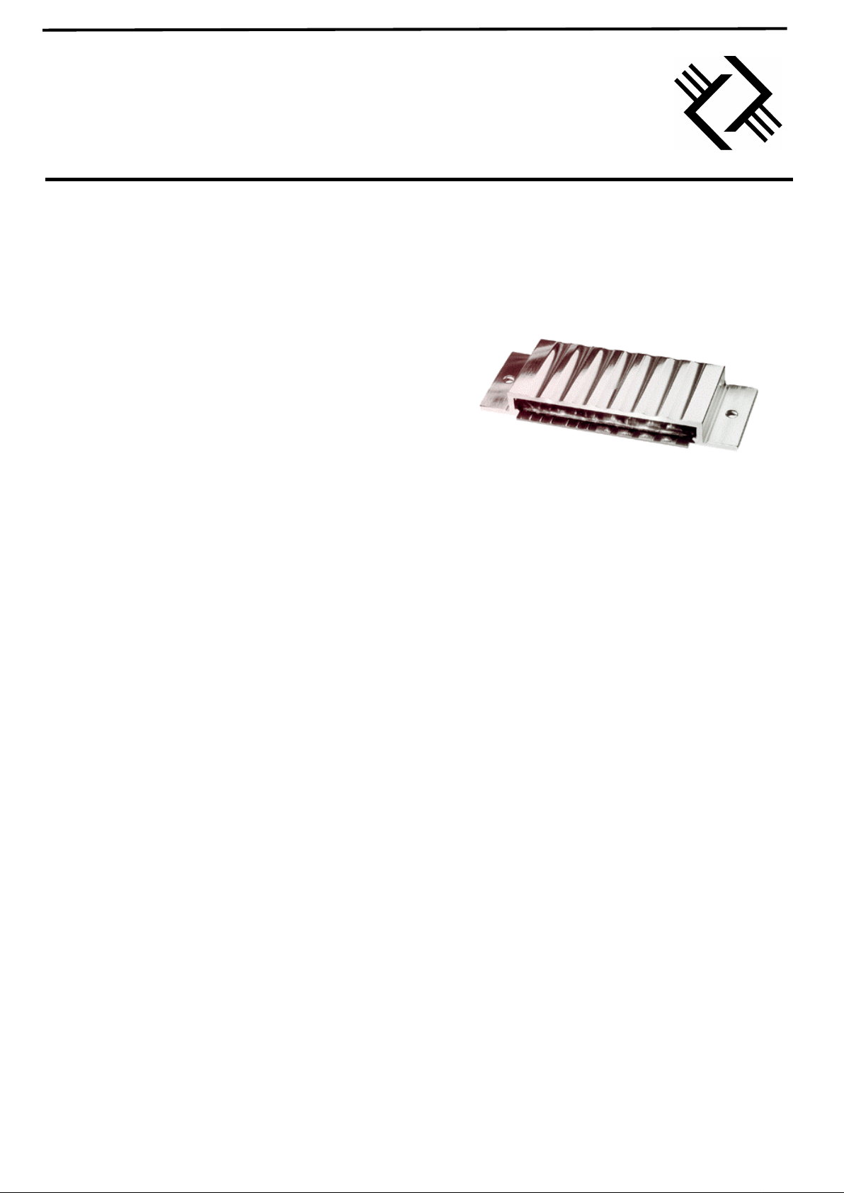
ECM-600H
600W RMS CLASS D AUDIO AMPLIFER MODULE
FEATURES
• HIGH POWER: 600W RMS
1
• HIGH EFFICIENCY ~90%
• HIGH SWITCHING FREQUENCY: 450KHz.
• LOW DISTORTION: <0.3% THD OPEN LOOP
• SIMPLE POWER SUPPLY REQUIREMENT
2
• THERMALLY EFFICIENT PACKAGE:
-INTEGRAL HEATSINK
-NO COOLING FANS REQUIRED
• LOW NOISE: NOISE FLOOR typ. 85dB DOWN
3
• EMC SCREEN INTEGRAL TO PACKAGE
• OVER TEMPERATURE PROTECTION OPTION
4
• OVER CURRENT PROTECTION OPTION
4
-PULSE BY PULSE
• LOW QUIESCENT CURRENT - MUTE FACILITY
• DRIVES A 16Ω, 8Ω AND 4Ω SPEAKER
5
• SLAVE MODULES CAN BE LINKED TO BOOST
DRIVE CAPABILITY (WITH MASTER OPTION)
• OTHER POWER OPTIONS AVAILABLE
1
• LOW COST
• LIGHTWEIGHT
• CUSTOM AMPLIFIER DESIGNS AVAILABLE
NOTES
1) Other power options include 2000W, 1000W, 300W, 150W and
50W. Alternately, custom power levels can be produced.
2) Companion PSU unit will be available early 2000
3) Assumes minimisation of external noise coupling and measured in
audio band only.
4) Contact Profusion for more details of these options
5) 2Ω speaker variant available
APPLICATIONS
• PROFESSIONAL AUDIO POWER AMPLIFIER
• ACTIVE SPEAKER SYSTEMS
• ACTIVE SONAR SYSTEMS
• NOISE CANCELLATION SYSTEMS
• MOTOR / MAGNET DRIVE MODULES
• POWER CONVERSION
• UPS - SINE WAVE INVERTER
DESCRIPTION
The ECM-600H is a complete professional audio power
amplifier module. The module contains power transistor
drive electronics, control and protection circuitry. Only a
power supply, decoupling capacitors and output filter
(optional) must be added to produce a stand alone
professional audio amplifier. The module is optimised to
drive a 4Ω load (16Ω, 8Ω and 2Ω optimised versions are
available). Modules can be ganged together to produce a
stereo amplifier. For higher power applications the
ECM-600H/SL slave module can be linked to the power
amplifier to increase the drive capability.
Please contact Profusion for a confidential discussion of
your requirements and further application information.
CLASS D AUDIO AMPLIFER MODULE
Profusion plc - Aviation Way - Southend-on-Sea - Essex - SS2 6UN UK
Tel: +44(0) 1702 543500 Fax: +44(0) 1702 543700 email:sales@profusionplc.com Website: www.profusionplc.com
Rail voltage, VRS ……………………………………………………………………..….... 100 V
Control voltages VL ………………………………………………………………………… +18 V
Total current into VL ..……………………………………………………………………. 150 mA
Operating free air temperature, TA …...…………………………………………… -10°C to 40°C
Storage temperature range, T
stg
…………………………………………………….. -40°C to 70°C
PCB solder pad temperature for 60 secs ……..…………………………………………….. 260°C
Stresses beyond those listed under absolute maximum ratings may cause permanent damage to the device. These are stress ratings only and functional operation
of the device at these or any other conditions beyond those indicated “recommended operating conditions” is not implied.
Recommended operating conditions
MIN TYP MAX UNIT
RAIL VOLTAGE, V
RS
0 65 80 V
POWER SUPPLY VOLTAGES, +V
L
10 12 14 V
AUDIO INPUT, S
2
0 +1 +1.09 Vp-p
MODULATION FACTOR 0 0.9 0.98
OPERATING FREE AIR TEMPERATURE, T
A
10 60
°C
Electrical characteristics at a free air temperature of 25°°C
VALUE
PARAMETER NOTES/TEST CONDITIONS VRS = 65 V UNIT
MIN TYP MAX
S
3
ENABLE INPUT
(Other input options available)
LEAVE UNCONNECTED OR
CONNECT TO 0V TO ENABLE
4.75 5 5.25 Vp-p
R
EN
ENABLE INPUT IMPEDANCE
10
KΩ
R
IN
AUDIO INPUT IMPEDANCE
(Other input options available)
7.3
KΩ
I
L
POWER SUPPLY CURRENT
RL = 4Ω
100 150 mA
I
RS
POWER RAIL CURRENT
RL = 4Ω
16
A
P
RR
ALLOWABLE POWER RAIL
RIPPLE
SEPARATE POWER SUPPLY
MODULE AVAILABLE
1 %
r
O
OUTPUT RESISTANCE
RL = 4Ω
100
mΩ
SNR SIGNAL TO NOISE RATIO
RL = 4Ω (in audio band)
-85 dB
f
SW
SWITCHING FREQUENCY
(Provisional)
450 KHz
t
PD
PROPAGATION DELAY
(POWER OUTPUT STAGE)
RL = 4Ω
150 ns
SPECIFICATIONS
Absolute maximum ratings
Profusion plc - Aviation Way - Southend-on-Sea - Essex - SS2 6UN UK
Tel: +44(0) 1702 543500 Fax: +44(0) 1702 543700 email:sales@profusionplc.com Website: www.profusionplc.com
The total coupled power from the input of the amplifier to the load is determined by three parameters.
These are:
1. The input signal level with respect to the maximum input level (Modulation factor)
2. The Inherent efficiency of the amplifier module.
3. The attenuation of the audio signal by the output filter (Filter attenuation).
Modulation Factor
The maximum input audio signal level for the amplifier is normally +1V peak to peak. For signal levels
greater than this range the amplifier will 'clip' which will produce a distorted signal. Driving the amplifier
into clip will not damage the module but will severely degrade the replication of the audio signal and can
in some cases damage the loudspeakers. At + 1V peak to peak the modulation factor is 0.9 i.e. the input
signal is at 90% of the full input range. If the input signal magnitude is well controlled, higher modulation
factors can be used. In practice 0.98 modulation factor (+1.09V peak to peak) should be considered the
absolute maximum and 0.95 (+1.05V peak to peak) should be adopted in applications where maximum
power coupled to the loudspeaker load is desirable. If the amplifier module is to be used at high
modulation factors we recommend using an anti-clip circuit. This circuitry can either be added by the user
external to the module or selected anti-clip options can be incorporated in to the package. For the various
options, please see the later section or contact Profusion.
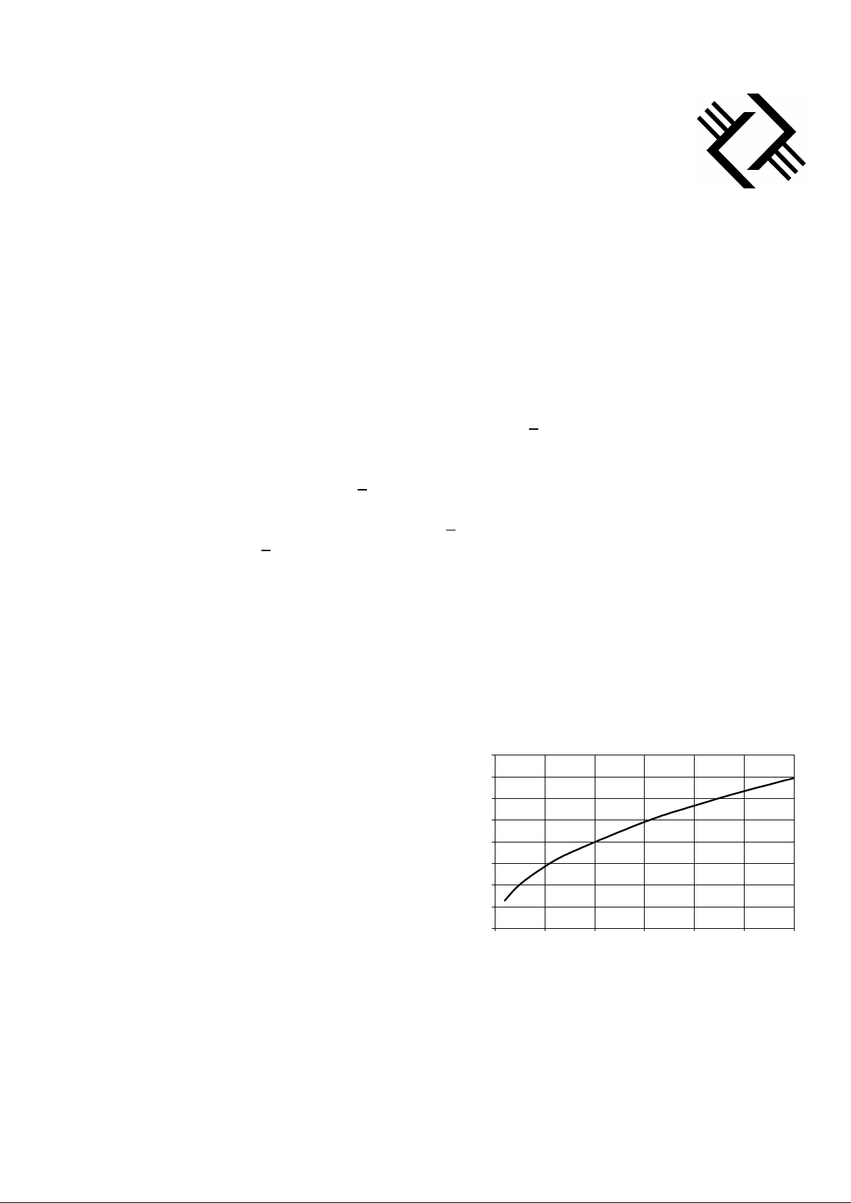
Inherent Efficiency
The amplifier modules are tested for the inherent
efficiency by measuring the power coupled into the
defined load (non-inductive dummy load). To calculate
the inherent efficiency, the differential voltage across
the load is measured for the defined rail voltage. The
control of the power output from the amplifier module
is achieved by varying the rail voltage. At a given rail
voltage the maximum theoretical output power is
given by the chart opposite.
For example, if the rail voltage is 20V and the
differential voltage across the load is measured at 38V,
the power into a 4Ω load would be:
OUTPUT POWER and EFFICIENCY
Total coupled power
Rail voltage versus maximum power into
a pure 4 ohm pure resistive load
0
10
20
30
40
50
60
70
80
0 100 200 300 400 500 600
Power (W)
Rail voltage (V)
Measured power = (38/2)2/(4 * 2) or 45Wrms
 Loading...