

Use Instruction
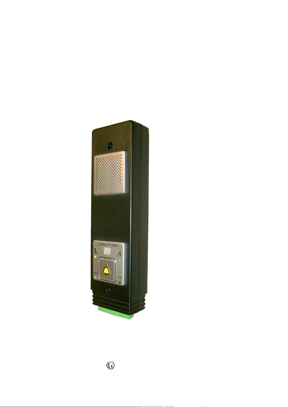
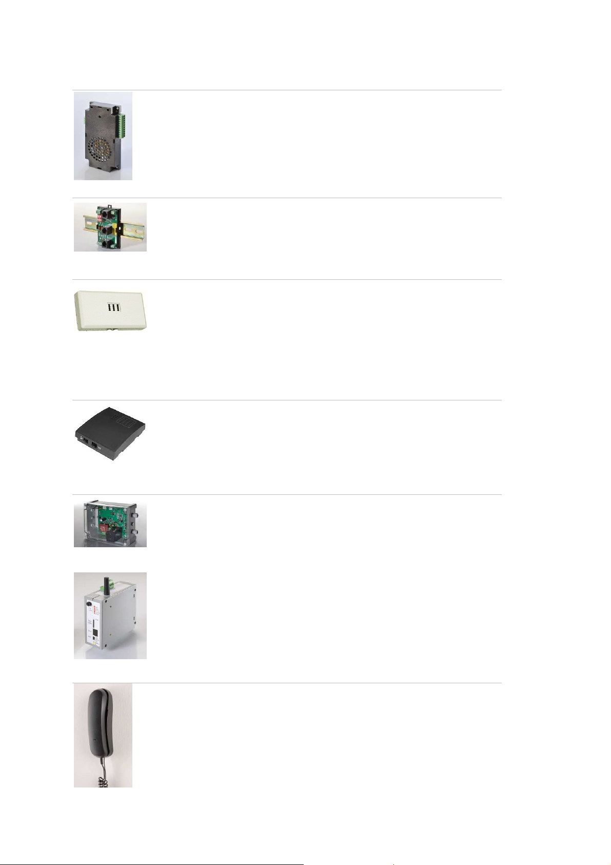
EXICALL® EN70
EXICALL® EN70MR
EXICALL® EN70-ATEX
Order-No. 121.5102 (upright version EXICALL® EN70)
Order-No. 121.5103 (horizontal version EXICALL® EN70)
Order-No. 121.5104 (upright version EXICALL® EN70MR)
Order-No. 121.5105 (horizontal version EXICALL® EN70MR)
Order-No.
121.5350 (upright version EXICALL® EN70-ATEX)
Issue 10.2013 | Version 8-48

Table of contents
Safety instructions . . . . . . . . . . . . . . . . . . . . . . . . . . . . . . . . . . . . . 3
EXICALL® EN70 . . . . . . . . . . . . . . . . . . . . . . . . . . . . . . . . . . . . . . . 4
Installation . . . . . . . . . . . . . . . . . . . . . . . . . . . . . . . . . . . . . . . . . . 5
Specification sheet . . . . . . . . . . . . . . . . . . . . . . . . . . . . . . . . . . . . . 6
Programming . . . . . . . . . . . . . . . . . . . . . . . . . . . . . . . . . . . . . . . . . 8
Installation. . . . . . . . . . . . . . . . . . . . . . . . . . . . . . . . . . . . . . . . . . 11
Commissioning . . . . . . . . . . . . . . . . . . . . . . . . . . . . . . . . . . . . . . 14
Operation . . . . . . . . . . . . . . . . . . . . . . . . . . . . . . . . . . . . . . . . . . 15
Functional description: Elevator alarm . . . . . . . . . . . . . . . . . . . . . . . . 18
Functional description: Door phone . . . . . . . . . . . . . . . . . . . . . . . . . . 20
Other Features . . . . . . . . . . . . . . . . . . . . . . . . . . . . . . . . . . . . . . . 21
Advanced programming . . . . . . . . . . . . . . . . . . . . . . . . . . . . . . . . . 23
Accessories . . . . . . . . . . . . . . . . . . . . . . . . . . . . . . . . . . . . . . . . . 29
Specifications . . . . . . . . . . . . . . . . . . . . . . . . . . . . . . . . . . . . . . . . 39
Declaration of conformity . . . . . . . . . . . . . . . . . . . . . . . . . . . . . . . . 40
2

Safety instructions
Telephone connection
EXICALL® EN70 is designed to connect to an ana logue telephone line. This
connection must remain in service for at least one hour after a mains power
loss according to EN81-28.
These are:
• analogue PSTN
• analogue por t of an ISDN terminal (ISDN-NT has to be
reprogrammed for emergenc y operation at the ab-port)
• analogue port of a private exchange using UPS (Uninterruptible
power supply 1h buffering)
• GSM Interface with TÜV approval, i.e. EA-GSM-Interf ace ☞ P.37
Multiple EXICALL® EN70 sharing one line:
• Ensure that the first alarm number is always available, because if
multiple alar ms triggered at the same time it is possible th at only
first number can be reached
• A maximum of three units can share one line
• In case of star c able routing (max. 15 Ω difference per connection
= Calc 2 x conductor resistance!) up to 4 diallers can be
connected. Example: AWG 24 (U72) = 2 x 90 Ω / km => difference
in length max. 15 Ω / (2 x 90 Ω / km) = 0.083km
• In case of a two-step-dialling-in the number of diallers is doubled
☞ P.26
Not suitable:
• VoIP or cable modem, as in case of power loss it is not functiona l!
The voltage of the telephone network is defined in EN 41003. It is higher
than 40 V and therefore please beware for electric al hazard and disconnect
the phone line during wiring.
Lightning protection interface for landline. ☞ P.37
Supply
Safety precautions
In case of a power loss EXICALL® EN70 can still dial calling number 1 using
power from the telephone line.
The components of the sub-unit EA-LMK and EA-LMK70B are connected to
the telephone line potential. Therefore, the connections must be transferred
free of soil and net (safety standard E N60950), and may not be touchable
(isolation 3.75kV).
Check functionality after each changing of parameter or wiring ☞ P.14
Please note an alarm by telephone is only succ essf ul if the subscriber takes
care of the following points:
• Alarm must not be answered by an answe ring machine or equal
equipment
• Sometimes conn ec ti on a mobile ph one can be red irec te d to a
“Combox” (Mailbox) directly or after some ringing-c yc les!
Do not open housing.
Do not bring the device into contact with a liquid (water).
3
EXICALL® EN70
View
➊
➋
➌
➍
➎
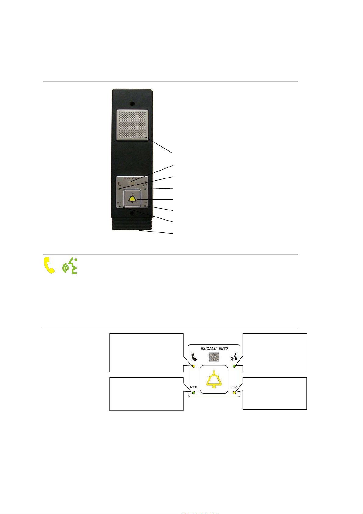
Functional elements
Meaning of LED indicators
➏
➐
➑
1. Speaker
2. Microphone
3. Yellow LED indicates “Call is activated” ☞ S.14
4. Green LED indicates “Please speak” ☞ P.14
5. Call button ☞ P.14 incl. backlight ☞ P.18
6. Red LED for K2, green LED for K3, yellow LED for K2 &K3 ☞ P.12
7. Green “Mode” LED ☞ P.8
8. Connections ☞ P.12
Yellow LED
Call is activated
LED-Mode
Gree n fl as h: standby
Gree n Ready for p rogram .
Re d ✆-connection active
Green LED
„Please speak“
idicates that remote
party is listening
LED-Output (Relais)
Re d K2 active
Gree n K3 active
Ye llow K2 & K3
4

Installation
Procedure
Proceed systematically. This will ensure that EXICALL ® EN70 is
installs correct and the function is ensured.
1. Complete specification sheet ☞ P.6
2. Is EXICALL® EN70 pre-programmed or do you program yourself?
Self programming ☞ P.8
Pre-programmed ☞ P.11
3. Montage ☞ P.11
4. Commissioning ☞ P.14
5. Operation ☞ P.15
5
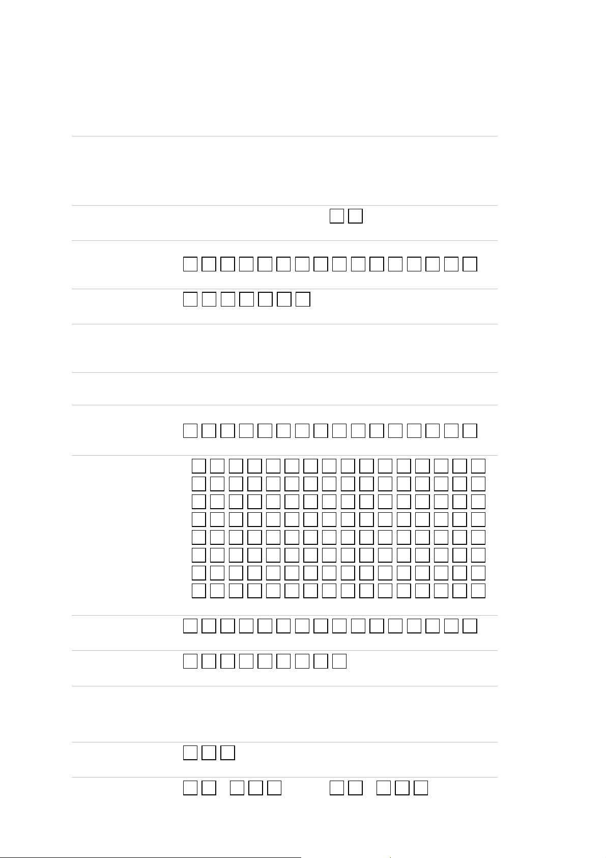
Specification sheet
General Information
Company: ________________________
Name: ________________________
Location: ________________________
Elevator no.: ________________________
Profile
Please see profile table below
Dial-in number
Telephone line where EXICALL® EN70 is connect ed
. . . . . . . . . . . . . . . .
PIN-Code
.
User language
❏
German
Dialling-in procedure
❏
with PIN-Code ❏ without PIN-Code
Serial-No.
❏
EXICALL® EN70
❏
French
❏
( Factory setting: 0000)
EXICALL® EN70MR
. . . . . . . . . . . . . . . .
Calling number(s)
1:
. . . . . . . . . . . . . . . .
2:
. . . . . . . . . . . . . . . .
3:
. . . . . . . . . . . . . . . .
. .
❏
English
❏
EXICALL® EN70-ATEX
❏
Italian
Periodical test call number
Dialling sequence
Individual announcement
User announcement type
Advanced programming
4:
. . . . . . . . . . . . . . . .
5:
. . . . . . . . . . . . . . . .
6:
. . . . . . . . . . . . . . . .
7:
. . . . . . . . . . . . . . . .
8:
. . . . . . . . . . . . . . . .
. . . . . . . . . . . . . . . .
. . . . . . . . .
_______________________________________________ __________ ______
_______________________________________________ __________ ______
(12 seconds at max)
. . .
(please see announcement table below)
. .= . . . . .= . . .
6
ANNOUNCEMENT
after
ANNOUNCEMENT
Profile table
Profile
0
1
7
8
9
10
Type of use
Speed dailing ☞ P.20
No speed dailing ☞ P.20
No misuse protection ☞ P.18
No misuse protection ☞ P.18
Misuse protection ☞ P.18
Misuse protection ☞ P.18
Dialing in /
Remote access
without
PIN-Code
without
PIN-Code
without
PIN-Code
without
PIN-Code
without
PIN-Code
with
PIN-Code
Individual
announcement
None
None
None
One time
One time
One time
User announcement type
11
Mit Missbrauch ☞ P.18
Factory default: Profile 10 Programming ☞ P.23
= Door phone = Elevator alarm
Value
0 One time
1. .2 00
20 1. .2 50
25 2
25 3
25 4
25 5 -
Factory default fo r el evator alarm: 0 Programming ☞ P.23
Factory default fo r door phone: 254
pressing call button
„Emergency call
activated, you are about
to be connected
bearbeitet“
„Activated“
every 1..200
201..250 sec.
with
PIN-Code
Repeated
seconds
Repeated
every
One time
Repeated
during phone
connection
Individual
announcement +
cause of alarm +
„to stop press 0“
„to speak press 1“
Individual
announcement
-
7

PROG
✓
Programming
Preparation
1. EXICALL® EN70 will be programmed locally over the microphone using
a DTM F-dialle r (Touch-Tone-Dialler). Therefo re, ambi ent noise can
affect the programming.
2. Connect supply voltage ☞ P.12
3. Place Dialler over the microphone.
Enable programming
Information on programming
4. Press call button briefly. The mode LED Mode changes from flashing to
5. Press key *. on the dialler. The mode LED changes to off.
6. A. You hear one beep fo llowed by the an nouncement "Programming
6. B. You hear one beep only. EXICALL® EN70 is now in programming
Programming will be PIN-code protected automatically after firs t call
The p rogramming mode is left automatically when there will be no
As long as the yellow LED is on, you are not able to do any
Programming remains stored even after power-los s.
permanently green.
disabled, PIN ". Enter th e PIN code (fac to ry setting: 0000) followed by
key #. . Y ou will hear two beep sou nds and the programming is
enabled. Wait for any announcements and conti nue wi th s te p 4. .
mode. Start programming sequence by entering first key within 5
seconds, otherwise programming mod e is exited (go back to step 4, if
you want to proceed with programming) .
started from the EXICALL ® EN70 to ensure that EXICALL ® EN70 is
protected against unauthorized changes after th e instal lation.
DTMF received within 5 seconds (=timeout).
programming. Wait until the yellow LE D is off.
8
PROG
✓
Calling number according
Wait for 5
BEEP
PROG
✓
ANNOUNCEMENT
BEEP
PROG
✓
r according
Wait for 5
BEEP
PROG
✓
Calling number according
Wait for 5
BEEP
PROG
✓
Calling number according
Wait for 5
BEEP
PROG
✓
Calling number according
Wait for 5
BEEP
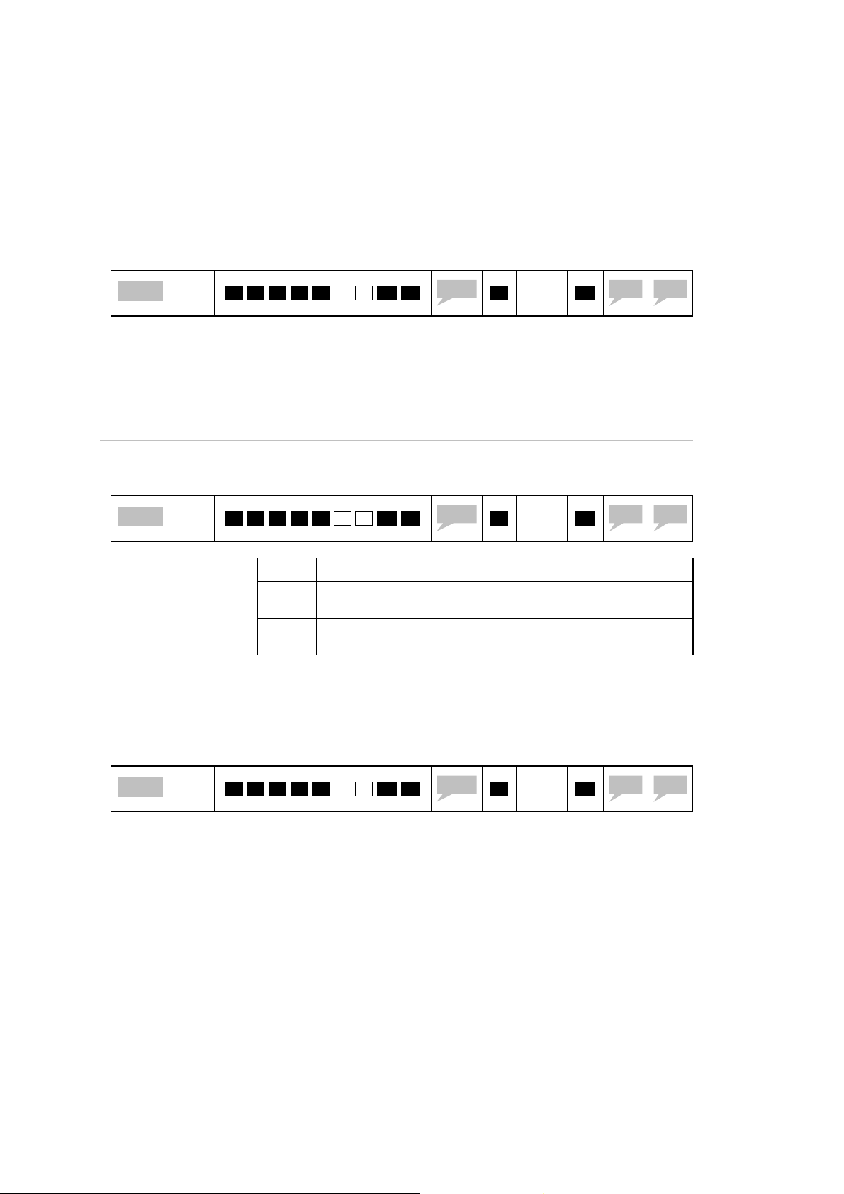
How to program calling numbers
* . * . 1 .
☞ P.8
* . * . 2 .
☞ P.8
* . * . 3 .
☞ P.8
.. .. .. .. .. .. ..
* . * . 8 .
☞ P.8
You can program up to 8 or 9 calling numbers.
If you want to alarm more than the first three calling numbers you
Calling number 9 is used for periodical test call according EN81-28.
Digit #. as part to the calling number results in a 5 seconds dialling
If you req uire Hotli ne-mode (= private exchange dials telephone
If the p riva te exchange needs flash-pulse to dial internal numbers you
Calling number 1 cannot be deleted and is the only calling number to
Digit *. as part of the calling n umber will result into a Point-ID-
ANNOUNCEMENT
ANNOUNCEMENT
ANNOUNCEMENT
ANNOUNCEMENT
have to adapt calling number sequence. ☞ P.9
delay. This may be necessary in combina tion with a private exchange,
when a pause is required after taking an external line. P rogram calling
number as following: Office Number + #. + Phone number
number after EXICALL® EN70 seizes line) you program calling number
1 with #. only.
have to progra m calling number as following: 2. # . + internal
number.
be dialled in case of a supply power loss.
connection. ☞ P.21
Calling numbe
* .
* .
* .
* .
to specification sheet
to specification sheet
to specification sheet
to specification sheet
sec.
sec.
sec.
sec.
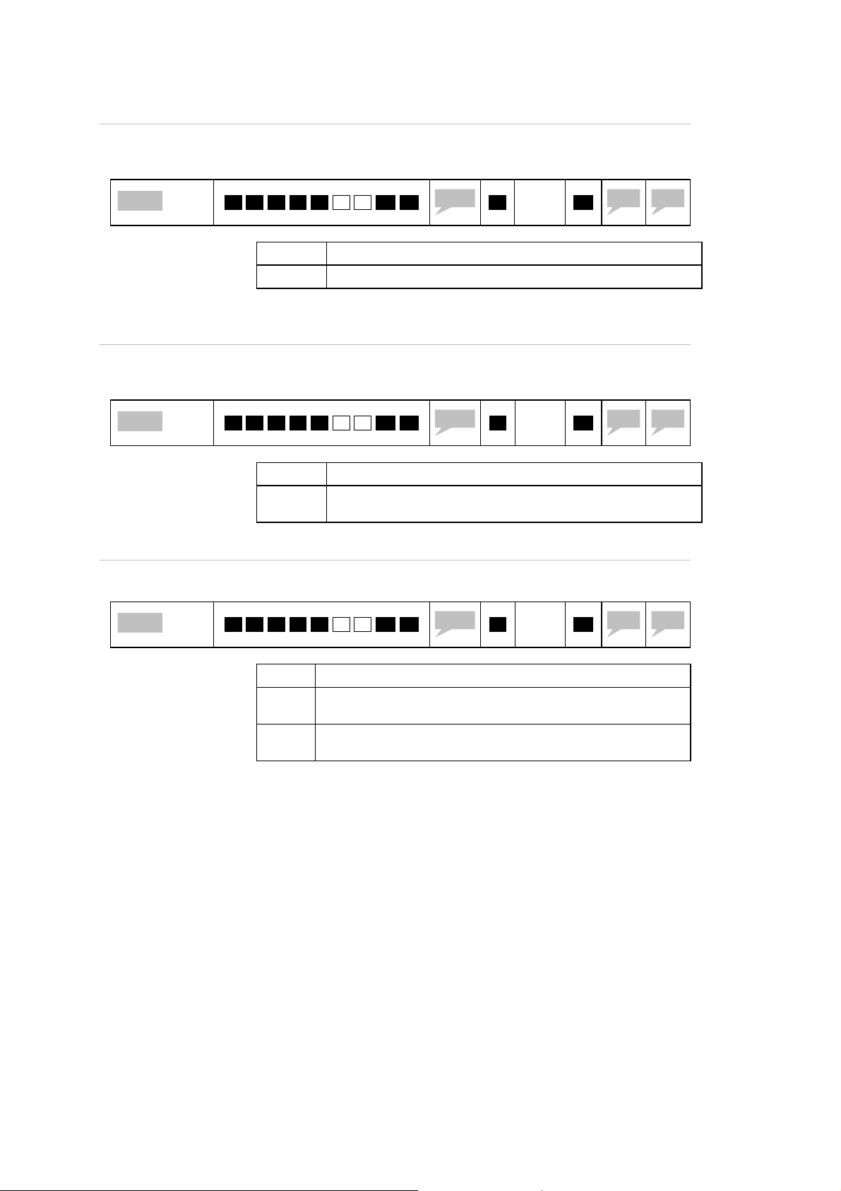
How to program periodical test number
According to EN8 1-28 EXICALL® EN 70 has to call his service facility at least
every 72 hou rs => periodical t es t call. Therefore you have to program
calling number 9.
* . * . 9 .
☞ S.8
If the periodical tes t call is activated EX ICALL® EN70 calls this number
The periodic al test can be ac tivated / de-activated i .e. during a remote
How to check calling numbers
Check calling numbers i.e. calling number 1 by ente ring:
ANNOUNCEMENT
in the programmed interval. ☞ P.25
access (dialling in) using DTMF commands. ☞ P.16
☞ P.8
* .
* . * . 1 .
to specification sheet
sec.
Wait for
20 sec.
9
PROG
✓
BEEP
BEEP
PROG
✓
ANNOUNCEMENT
BEEP
Wait for
PROG
✓
Wiat for 5
BEEP
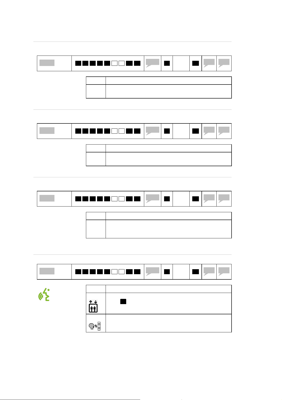
How to program calling number sequence
The factory default f or calling number sequence is 1. 2. 3.. EXICALL®
EN70 calls the numb ers of the sequence consecutively unt il the call is
acknowledged or the end of the sequence is reac hed.
You can adapt the sequence in case yo u want to ca ll a certain number
repeatedly.
Examples:
Calling number sequence fa ct or y setting 1. 2. 3 .: Call number 1, then
number 2 followed by number 3.
Calling number sequence 1. 1. 3. 3 . 2. 2. 2. 2.: Call number 1 two
times, followed by two attemp ts on number 2, followed by four attempts on
number 3.
Calling number sequence 2. 3. 1. : First call to number 2, than number
three and number 1 in the en d. In case of a power loss only calling number
1 can be dialled.
* . * . 0 .
☞ S.8
The calling number sequence can contain up to 9 digits.
The calling number sequence may be altered using day/night-input
If a calling number is not programmed or erased, this number will be
In case of a power loss EXICALL® EN70 can alarm calling number 1
Unit powered In case of power loss
Calling number sequence 231 Calling numbe 1 only
2: 0#044… 1: 0#043…
3: 0#079… -
1: 0#043… -
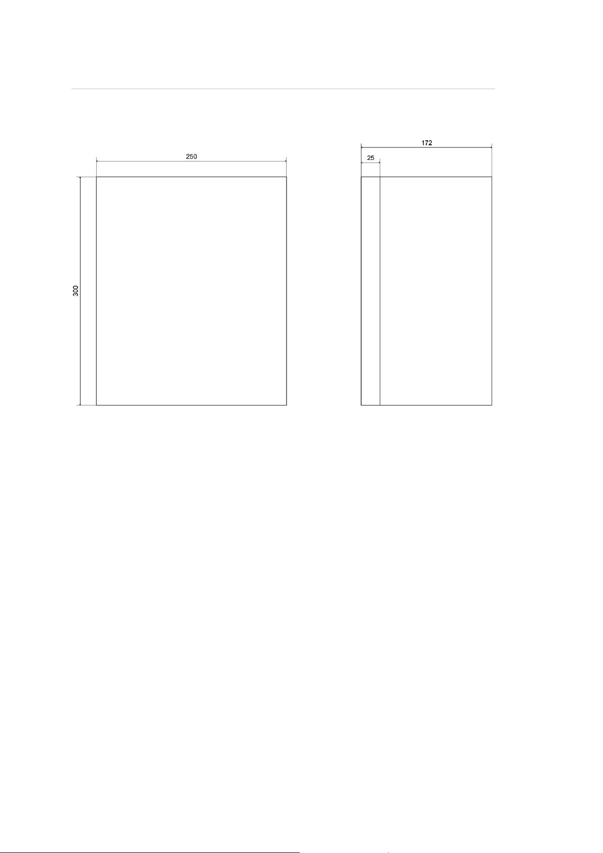
How to program individual announcement / Select langu age
You can record an individual announcement to identify your EXICALL®
EN70. The optio nal input <n> allows altering the user la nguage: Press 1.
for German, 2 for French, 3. for English, 4. for Ital ian.
ANNOUNCEMENT
(S4). If so, enter calling n um ber other sequence while input signal S4
is active. During operation the calling number sequence follows the
input signal on S4. ☞ P.21
skipped when still programmed in calling number sequence.
only. Please make sure that at least on calling number is available in
any case at any time, i.e. calling number sequence= 2 31:
Calling cumber sequence
* .
accordign to spec. sheet
sec.
☞ P.8
How to program the PIN-Code
☞ S.8
* . * . # .
The maximum recording time is 12 seconds
Depending on the selected profile this announcement will be played
The PIN code protects the EXICALL ® EN70 against unauthorized r emote
dial-up or prog ramming. It also can be us ed to identify the unit du ring
phone connection (i.e. commission number of e levato r)
PIN code accroding to
# .
The PIN code must be between four and s even d igits.
The factory se tt in g for the PIN code is 00 00 . Program a different
once at the beginning of each alarm connec tion, or repeated every <x>
seconds during the connection or even without an y announcement (i.e.
as door phone) ☞ P.7
specification sheet
code for security reasons.
<n > * .
# .
Announcement
according to
specification sheet
Re pe at P IN
code
# .
# .
5 sec.
10

Montage
Mechanical Assembly
Front panel
Mounting accessories
Flash-mounting front panel: Alum or stainless steel ☞ P .2 9
MDF housing (wall insert) for front panel ☞ P.31
Die-cast aluminium box for surface mo unting ☞ P.32
ABS-enclosure with transparent door for surface mounting ☞ P.33
Front panel (Alum) suitable for ABS-enclosure ☞ P.34
Flash-mounting front panel (Exitel upgrade cover): stainless steel ☞
P.35
11

Wiring
The electrical wiring is split into supply, telephone l ine and the pe riph ery.
Proceed as follows:
Connect the two-wire shielded phone line.
Connect supply voltage. EXICALL® EN70 performs a se lf t est. ☞ P .1 4
Start test call. Press call button for one second. ☞ P.14
Connect accessory and or input/output.
Supply voltage (X12:3 poles)
10 – 35V DC or 8 – 25 V AC
If you power by mains, us 230V AC
power adapter.
Line (X1:RJ12)
EXICALL® EN70: two wire (red/green)
MR-type: fore wire
(red/green,black/yellow)
Twisted and shieled and free from
connection to other wires.
Ca ll button backlight
- Shunt PIN 1 and 2
Input-/O ut pu t (X13:12 pole)
- Misuse protection signal (S1):
Connect signal according to the
elevators door state.
- External call signal (S2):
not ready in case of power loss!
- Alarm signal (S3)
- Day-/Night switching signal (S4)
If you want an individual calling
number sequence.
- Parallel contact (K1)
Potential free contact of call
button.
- Systeme contact (K2):
Connection to a building control
system (filtered alarm) or
connection of video, light
or display "help omes."
- Door opener contact (K3):
Connect door opening system in
case of intercom use.
Accessory (X2:RJ45)
- Sub-unit EA-LMK:
- Sub-unit EA-LMK70B
- Potential free external call button
12

Terminals
12 11 10 9 8 7 6 5 4 3 2 1 3 2 1
Supply voltage X12
Telephone line X1
Leitronic-Accessories X2
X1 3
X2
X1 2
PIN 1
PIN 2
PIN 3 SP
X1 Color Function
PIN 2 Black to machine rrom Telefone or remote-unit
PIN 3 Red to PSTN (connection a)
PIN 4 Green to PSTN (connection b)
PIN 5 Yellow to machine rrom Telefone or remote-unit
Description
GND Earth
SP
Function
Supply voltage
10 - 35 V DC or 8 - 25 V AC
max. 4 W, arbitrary polarity
LMK72B
LMK72B
X1 2
X1
Input/Output X13
X2
Terminal for Leitronic accessories
X1 3
PIN 1
PIN 2
PIN 3
PIN 4
PIN 5
PIN 6
PIN 7
PIN 8
PIN 9
PIN 10
PIN 11
PIN 12
Signal inputs (S1 - S4) active: 10 V - 40 V AC/DC
Output contact (K1/K3) Normally open max. 4 A/50 V AC/DC
Output contact (K2) Normally closed max. 100 mA/50 V AC/DC
Descreption Function
BEL
BEL
K3
K3
KCOM
K1
K2
SCOM
S4
S3
S2
S1
White backlight
White backlight
Relay (Normaly open) i.e. door opener
Relay (Normaly open) i.e. door opener
Common pole for relay K1 and K2
Call button parallel contact (Normally op en)
Filtered alarm contact (Normally clos ed)
Common pole for signal inputs S1-S4
Day/Night input signal
Technical alarm signal
External alarm contact
Misuse protection signal (i.e. door state)
13

Commissioning
Connecting supply
After power up EXICALL EN70 ® starts a self -tes t, checking for. .
Telephone line: If no dial tone is detected, you will hear the
announcement "phone line failure". Please c heck phone line.
Alarm input S3: If the input is active, you will hear the announcement
"Sensor-3 activated.
Call
Press the call button at least one second to start call.
Setup connection
During two minutes EXICALL® EN70 tries to establis h connection. Adjusting
timer ☞ P.25. During this time-out the LED “Telephone” is a ctivated.
During connection setup the user annou ncement will be played o nc e,
repeated or ignored depending on selected profile. Adjust user
announcement type ☞ P.7
If there is not connection please check calling number. ☞ P.9
Hands-free connection
Terminate connection
Called party can listen to the user announcement or skip announcement by
sending DTMF command 1 . or 3 . ☞ P.15. Doing so activates LED “Sp eak” .
Check if hands-free communication is fine. Beware of the hands-free
connection timeout of 2 minutes ☞ P.25. 10 seconds before disconnecting
EXICALL® EN70 plays announcement „Abort“. The connection t imer can be
re-started using DTMF command 1. or 3..
Called party can terminate call by sending DTMF command 0. . Other
commands ☞ P.15
14

Pass on Alarm to next
Read out PIN code
Arm system
Stop announcements and
Status information
Activated output
K2
Play announcements:
Acknowledge alarm
Switch to hands
-
free
connection
Dea
ctivated
Disarm system
Additional
remote
commands
Operation
Answer call
During connection the called party can initiate remote instructions by
sending the following DTMF commands:
Individual message / Cause of alarm
output K2
☞ Table below
and disconnect
2 3 1
reload connection timer
5 6 4
8 9 7
0 # *
If more than one alarm number is programmed ☞ P.9, the call must be
acknowledged /answered by sending DTMF comman d 0.. O therwise
EXICALL® EN70 starts to dial the next alarm number.
If you want to pass on the alarm to the next alarm numb er
immediately, you can do so by sending DTMF command 8. .
(Identification)
alarm number
15

Other remote controls / Elevator alarm and Door pho ne mode
Do not delay more than two seconds between two digi ts.
DTMF commands
* . * . 0 .
* . * . 1 .
..
* . * . 8 .
* . * . 9 .
* . * . # . 0.
Read-out/ Modify calling number sequence (1->-2->3)
Read-out / Modify calling number1
..
Read-out / Modify calling number 8
Read-out / Modify periodical test number
Deactivate periodical test to calling number 9
* . * . # . 1. <n>
* . * . # . 2.
* . * . # . # .
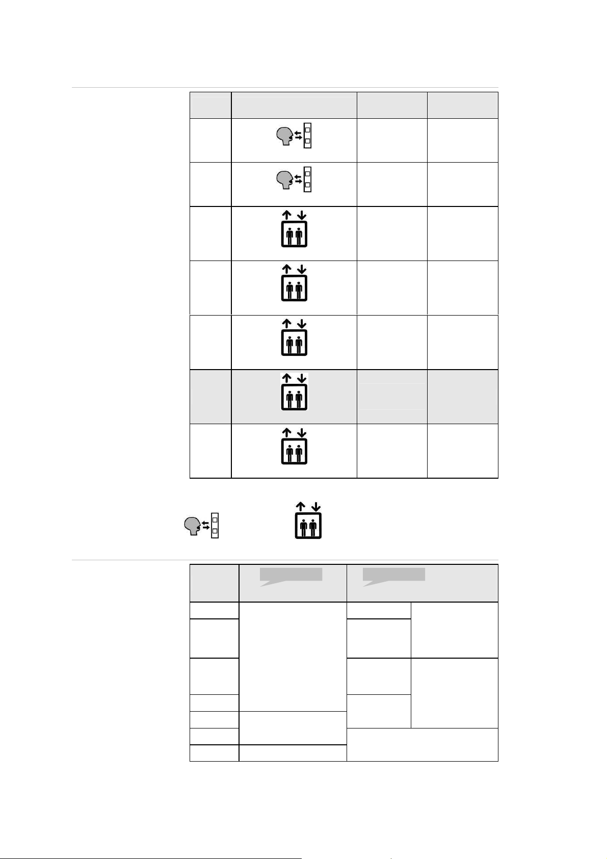
Other remote controls / Door phone
DTMF commands
* . 2 .
* . 3 .
* . 4 .
* . 5 .
* . 6 .
* . 7 .
* . 8 .
* . 9 .
* . 0 .
* . 1 .
Activate periodical test to calling number 9 (first time in 72 h or after <n>
hours)
Start communication test to calling number 9 in two minutes (once only)
Modify individual message
Do not delay more than two seconds between two digi ts.
Close contact K3 for 2 seconds Yes
Close contact K3 for 4 seconds Yes
Close contact K3 for 8 seconds Yes
Contact K3 on 3s, off 1s, on 3s Yes
Close contact K3 for 2 seconds No
Close contact K3 for 4 seconds No
Close contact K3 for 8 seconds No
Close contact K3 until disconnection No
Disconnect if S1 (door contact) is active If input S1 is active
EXICALL® EN70 disconnects Yes
EXICALL® EN70
disconnets
16

0000
Dialling in/Remote access
There are tw o ways of remote access: <with PIN-Code protection> or
<without PIN-Code> according to selected profile. ☞ P.7
Dialling in/Remote access without PIN-Code
Dial phone number of EXICALL® EN70. After selected r ingi ng-cycles ☞ P.26
EXICALL® EN70 answers call and changes to hands -free connection. This
change wi ll be sig nall ed by three gongs and the green “Speak”-Symbol
(EN81-70). So a person ins ide the cabin will be informed abou t the
established hands-free connection.
Dialling in/Remote access using PIN-Code
Dial number of EXICALL® EN70. After selec ted ringi ng -cycles ☞ P.26
EXICALL® EN70 answers call and asks for PIN (Default = 0000). If the
correct PIN-Code is entered, EXICALL® EN70 changes to servic e-mode
where the microphone and speaker remain inactive followed by the
announcement “to stop press 0, to speak press 1”.
With ke y 1. you can change to hands-fr ee-c onnection. This change will be
signalled by three gongs and the green “Speak”-Symbol (EN81-70). So a
person inside the cabin will be informed about the established hands-free
connection.
Dialling in/Remote access: Special mode: Two step dialling in
Dial ph one number of EXICALL® EN70. Let it ring two times and hang-up.
Wait for 20 seconds and re-dial phone n umber. After selected ringing-cycles
☞ P.26 EXICALL® EN70 answers call !
Dialling in/Remote access: Special mode in case o f power lo ss
In case of a power loss on supply terminal EXICALL® EN70 answers call
immediately!
17

AN NO UNC EME NT
AN NO UNC EME NT
AN NO UNC EME NT
AN NO UNC EME NT
Functional description: Elevator
alarm
Elevator emergency call
If the emergency call is triggered by pressing the emergency button for at
least one second ☞ P.24 the yellow indicator is activated. EXICALL® EN70
dials the programmed number(s) and established a hands-free connection.
When the called party sends DT MF command 1. the LED „Speak “ is
activated.
Call button backlight
Misuse-Protection (S1)
To activate the push-button backlight short the two BEL ter minals .
The misuse protection signal is used to separat e real emergency calls.
During the max imum duration of cabin travel ☞ P.24 you will hear the
announcement:
If the door state changes during this timeout you will hear:
acknowledged“
If the door state does not alter during this timeout E XI CALL® EN70 starts
to dial the calling number(s) playing
Factory setting for misuse timeout: 30 second s. ☞ P.24
Misuse-protection is only available when supply voltage is applied.
Connection to building control system. ☞ P.19
There are two ways to connect mis use-protec tion s ignal:
1. Connect voltage following the 2. Use supply voltage SP and connec t
door state between S1 and SCOM. door contact.
„Emergency call activated. You are about to be connect ed“
„Emergency call activated. You are about to be c onnected .“
„Door is open. Emergency call deactivated. A larm
„Emergency call activated“
S1SCOM
SCOM
S1
active: 10 V - 40 V AC/DC
SP
Door contact
SP
18
AN NO UNC EME NT
External alarm signal (S2)
System contact (K2)
SCOM
S2
SP
Alarm-
SP
Note: This optocoupler input cannot be used in case of a supply pow er loss.
Alternative: Potential free call button (normally open) connected to the sub-
unit EA-LMK/EA-LMK70B or connected using suitable connection cord
between PIN 3 and 6 (EXT-terminal).
The normally cl osed contact (K2) is used in the emergency lift profi les as a
filtered alarm ( for connection to a building management system) or activate
display " Help is com ing" display. While K2 is active the LED K2/ 3 is red or
yellow.
When K2 is used as in mode "fil tered alarm" the c ontact is activa ted after
the abuses o f misuse timeout ☞ P.24 and deactivated when the door state
changes.
When used in m ode "help is coming" K2 contact is activated after rece iving
DTMF command 6. and deactivated when the doo r state changes or if the
alarm remains unacknowledged.
Setting the K2 mode ☞ P.26.
contact
K2KCOM
to management system or "help is coming" lamp
100 mA/50 V AC/DC
Periodical test call (WinMOS®300)
According to EN81-28 a dialler has to indicate its s tate at least every 72
hours. EXICALL ® EN70 can perform this test call towards calling number 9
automatically ☞ P.9
The peri odical test can be activated during remote ac cess ☞ P.17 using
DTMF command sequence *. *. #. 1. . ☞ P.16
„Periodical test activated“
Adjust periodical test timer ☞ P.25
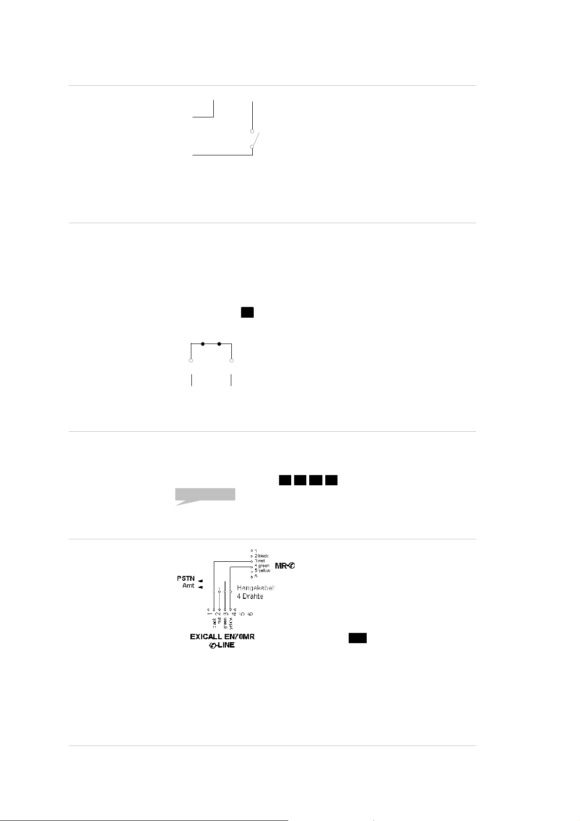
Machine room communication (EXICALL EN70MR only)
disconnected if EXICALL® EN70MR has to dial out due to an alarm.
In case of d ialling-in EXICALL® E N70MR can be adjusted to work together
with the machine room phone or modem ☞ P.17.
This functionality men ti oned above is only available w ith applied power. In
case of power loss, the machine ro om handset/modem and EXICA LL®
EN70MR are connected in parallel to the PSTN.
Connect PIN 3/4 of the machine room
phone MR-✆ with PIN 2/5 of ✆-LINE
terminal X1 of the EXICALL® EN70MR.
Lifting up the machine room handset
starts a hands-free connection w ith t he
cabins EXICALL® EN70MR indicated by
the green LED “Speak”.
Hanging up th e handset terminates
hands-free connection. By d ialling the
prefix 0. the hands et/m odem is
connected to the external line.
An existing external connection will be
Fire brigade solution according to EN81-72 (EXICALL EN70MR only)
☞ P.38
19

AN NO UNC EME NT
Functional description: Door phone
Door phone (Intercom)
A call is triggered by pressing the button for at least one second ☞ P.24
indicated by the yellow LED. E XICALL® EN70 dials the programmed
number(s) and established a hands-free connection. When the called party
sends DTMF command 1. the LED „Speak“ is activat ed.
„Activated“
Call button backlight
To activate button backlight connect the two BEL termin als.
Intercom with speed dialling
EXICALL ® EN70 can be used to call individual numbers according to the
activated buttons => i.e. cal l several apartments of a house (intercom).
Button T1 to T6 dials corresponding calling numbers 1 to 6. The internal
call button of the EXICALL® EN70 is equal to button T1. To activate speed
dialling select profile 0 ☞ P.23
System contact (K2)
Door opener contact (K3)
SCOM
VOC-
SP
SP
VOC+
min. 10 V
The normall y closed contact (K2) is used in all door phone profiles as
switching output for video / lighting. If K2 is active LED K2/3 is red or
yellow. K2 opens when a call is act ivated and closes 2 minutes after
terminating the connection.
S3 S2 S1
T3S4T1 T2T6 T4 T5
K2KCOM
Video/Light
Supply
You can use contact K3 to open a door or barrier. If K3 is active the LED
K2/3 is green or yellow.
There are several DTMF commends to activate/deactivate K3 ☞ P.16
K3K3
to door opener
max. 4 A/50 V AC/DC
20

Other Features
Service mode connection
The service c onnectio n is used in case of a silent alarm or remote access.
In service m ode microphone and speakers remain inactive. This connection
mode is used i.e. in case of a technical alarm (S3 ☞ P.21) or periodic al test
(☞ P.9) and depending on the settings at dialling-in ☞ P.27 .
During service mode DT MF command 1. swi tc hes to the hands-free
connection indicated by three gong signals.
Alarming using alarm protocols
EXICALL ® EN70 supports protocols Point-Contact ID or Contac t-ID. Thus,
the alarm can be routed to most emergency operations centre. When an
alarm is triggered EXICALL ® EN70 first transmits protocol to first calling
number followed by a second call using hands-free connectio n.
Enable Point-ID transmission ☞ P.28
Parallel contact (K1)
Contact (K1) is the potential free parallel contact of the ca ll button. K1 can
be used for the connection to a build ing co ntrol system or a doorbell.
Technical alarm input (S3)
Day/Night input signal (S4)
K1KCOM
to building control system / door bell ma
The response on the alarm input (S3) can be selected accord ing to ☞ P.2 4
If a signal is applied: If a contact is connected:
x. 4 A/50 V AC/DC
SCOM
S3
SP
S3SCOM
Alarm-
active: 10 V - 40 V AC/DC
Two different calling number sequences can be determine d depending on
the signal at input S4.
Program individual calling number sequence, once when S4 is active and
once when S4 is inactive.
During operation EXICALL ® E N70 dials calling numbers according to calling
number sequence depending on the state of S4 (day/night).
If a signal is applied: If a contact is connected:
SP
SCOM
S4
contact
S4SCOM
active: 10 V - 40 V AC/DC
SP
Day/Night-
SP
contact
21
ANNOUNCEMENT
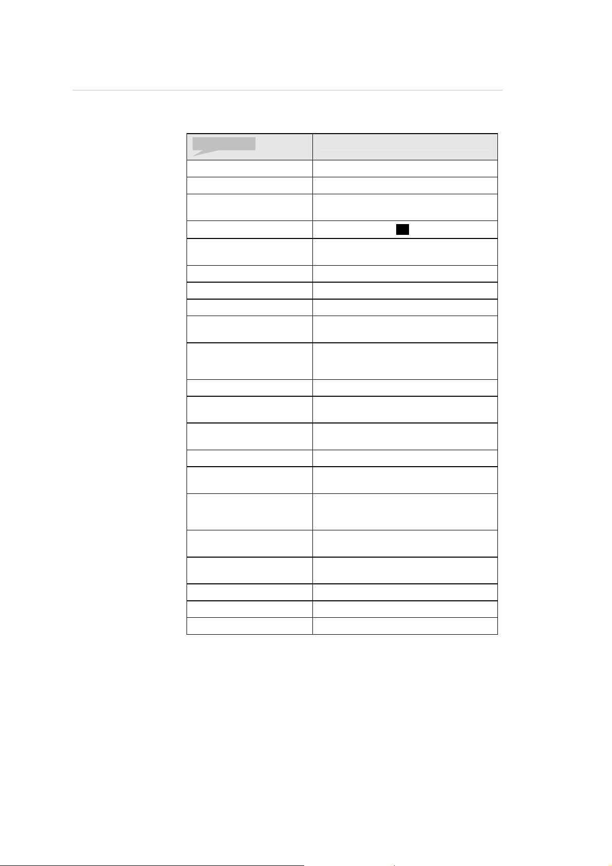
Announcement overview
Announcement depends on selected profile and can be adjusted according
to ☞ P.7
Announcement overview:
Individual announcement First annou ncement in case of an alarm
„Abort“ Connection will be terminated
„Alarm due to S1/S3“ Alarm du e to s igna l appl ied to s ensor 1 or
„Alarm acknowledged“
„To change press star, to
stop press hash“
„Output activated“ Relay K2 is activated
„Surveillance 1 activated“ No signal on input S4 (Day/Night)
„Surveillance 2 activated“
„Emergency call activated“ Emergency call activated by pressing call
„Emergency call
deactivated, alarm
acknowledged“
„PIN“ Prompt to enter PIN code
„Programming deactivated:
PIN“
„Programming
acknowledged“
„Programming, Abort“ Remote pr ogramm ing not successful
„Line failure“ No dial tone present during self test af ter
„Door is open. Emergency
call deactivated, alarm
acknowledged “
„Failure“ Erroneous entry during programming. The
„Unacknowledged alarms:
n“
„Calling number“ Calling number announcement
„Calling number sequence“ Calling number sequence ☞ S.9
„Periodical test“ A periodical test call is active ☞ S.19
Cause
3 inputs
If DTMF command 0. was sent
User guidance during programming
Signal on input S4 (Day/Night)
button
Emergency call has been acknowledged
or cancelled by changing door state
during misuse protection timeout
Prompt to enter PIN codes to enable
programming mode
Remote programming succes sful
power up
Emergency call is cancelled due to
change of door state during misuse
protection timeout
old value retain active
Number of unacknowledged alarms
22
PROG
✓
VALUE
BEEP
BEEP
PROG
✓
VALUE
BEEP
BEEP
PROG
✓
VALUE
BEEP
BEEP
Advanced programming
Attention: Changing these paramet ers below does influence the operating
mode. Therefore only necessary parameters should be changed. Please
check behaviour before going into operation.
Profile selection read/change
Table with all profiles according ☞ P.7
☞ P.8
Factory settings
Alarm repetition
☞ P.8
Announcement type
* . 9 . 7 . 1. 3 0 1 #. #.
Programming profile does not change calling numbers, calling number
sequence and individual announcement. But all other parameters and
registers and the PIN-code will be set to default value.
If you want to reset to factory default please re-program profile. ☞ P.23
EXICALL® EN70 calls calling numbers according to the calling number
sequence ☞ P.10 for every new alarm event. You can read-out or modify
this register as following:
* . 9 . 7 . 1. 3 5 3 #. #.
Value Descriptio n
0
1 - 9
Select announcement type according to table ☞ P .7
Note: Different factory settings according to p rofile!
You can read-out or modify this register as following:
EXICALL® EN70 calls calling numbers of the sequence o nce
per alarm even (Factory setting)
EXICALL® EN70 repeats calling number sequence 1 – 9 times
or until the alarm is acknowledged.
* .
* .
Value
Value
# .
# .
* . 9 . 7 . 1. 3 2 0 #. #.
☞ P.8
* .
Value
# .
23
PROG
✓
VALUE
BEEP
BEEP
PROG
✓
VALUE
BEEP
BEEP
PROG
✓
VALUE
BEEP
BEEP
Misuse timeout (sensor S1)
If the d oor state changes withi n the specified tim eout an emergency call
will be cancelled automatically. Adjust timeout according to maximum
duration of cabin travel. You can read-out or m od ify timer as following:
* . 9 . 7 . 1. 3 4 8 #. #.
☞ P.8
Value Description
20 - 255 Timer in seconds (Factor y se ttin g: 3 0)
Change profile if you want to de-activate misuse-protection!
Activation time for call button S2
EXICALL® EN 70 starts call when the call button has been activated longer
as certain time is pressed f or a specified time. You c an read-out or modify
timer as following:
* . 9 . 7 . 1. 3 7 9 #. #.
☞ P.8
Value Description
25 - 255 Activation timeout in 20 ms-steps. ( Fa ct or y se tt in g: 5 0 * 20
Technical alarm (sensor S3)
The activation type f or technical alarm signal S3 can be read-out or
modified as following:
ms, => 1 second)
* .
* .
Value
Value
# .
# .
☞ P.8
* . 9 . 7 . 1. 3 6 1 #. #.
Value Descriptio n
1
3
Announcement „Alarm due to sensor 3“, in case signal is
applied (Factory setting)
Announcement „Alarm due to sensor 3“, in case signal there is
no signal applied
* .
Value
# .
24
PROG
✓
VALUE
BEEP
BEEP
PROG
✓
VALUE
BEEP
BEEP
PROG
✓
VALUE
BEEP
BEEP
PROG
✓
VALUE
BEEP
BEEP
Dial-up connection time-out
During this timeout EXICALL® EN70 tries to establish co nnecti on. You ca n
read-out or modify timer as following:
* . 9 . 7 . 1. 3 5 0 #. #.
☞ P.8
Value Descriptio n
1 - 255
Hands-free connection time-out
During this timeout EXICALL® EN70 stays in hands-free connec tion. You
can read-out or modify timer as following:
* . 9 . 7 . 1. 3 5 1 #. #.
☞ P.8
Value Descriptio n
1 - 255
Periodical communication test
The timeout between two periodical calls can be read-out or modified as
following:
* . 9 . 7 . 1. 3 2 8 #. #.
☞ P.8
Timeout in steps of 10 seconds
(F actory setting: 12 * 10, => 120 s=2 minutes)
Timeout in steps of 10 seconds
(F actory setting: 12 * 10, => 120 s=2 minutes)
* .
* .
* .
Value
Value
Value
# .
# .
# .
Green indicator LED “Speak”
The activation type can be read-out or modified as following:
* . 9 . 7 . 1. 3 6 9 #. #.
☞ P.8
Value Descriptio n
1 - 254
Value Descriptio n
2
4
EXICALL® EN70 starts call to calling number 9 eve ry 1 – 254 *
20 minutes.
(F actory setting: 21 6 * 20min=4320min=72h)
LED Speak will be activated manually during connection usin g
DTMF 1 . (Factory setting for elevator alarm).
LED Speak is activated automatically after connection is
established (Factory setting for door phone).
* .
Value
# .
25

PROG
✓
VALUE
BEEP
BEEP
PROG
✓
VALUE
BEEP
BEEP
PROG
✓
VALUE
BEEP
BEEP
Relay K2 (LMK-OUT)
The function of this relay can be read-out or modified as fol lowing:
* . 9 . 7 . 1. 3 3 7 #. #.
☞ P.8
Value Descriptio n
0
1
193
208
Program ringing cycles / dialling-in
The number of r ingi ng cycles before EXICALL® EN70 ans wers the call can
be read-out or modified as following:
K2 inactiv (Factory setting for elevator alarm without
Misues-protection)
„Video/Light“ (Factory setting for door phone)
Relay will be activated by activating call button.
Relay will be de-activated two minutes after discon nect ion.
„Filtered alarm“ to connect to master control system
(F actory setting f or e le va tor alarm):
Relay is activated when alarm is activated (after the mis use
timeout).
Relay is deactivated if door state as changed.
„Help is coming“:
Relay is activated using touch-tone 6. .
Relay is de-activated if the door state changes or an alarm
remains unacknowledged.
* .
Value
# .
☞ P.8
Dialling-in sequence
☞ P.8
* . 9 . 7 . 1. 3 4 7 #. #.
Value Descriptio n
0 EXICALL® EN70 does not answer incoming call
2..9 EXICALL® EN70 answers call after 2 - 9 ring ing cycl es
(F actory setting: 2)
In case of a power loss this setting is no t relevant => EXICALL® EN70
answers call immediately.
Behaviour on dialling-in mode can be read-out or modi fied as foll ow ing:
* . 9 . 7 . 1. 3 7 0 #. #.
Value Descriptio n
0 Direkte Ferneinwahl (W er ksei nste llung)
1 Etappierte Ferneinwahl
* .
* .
Value
Value
# .
# .
26

PROG
✓
VALUE
BEEP
BEEP
PROG
✓
VALUE
BEEP
BEEP
PROG
✓
VALUE
BEEP
BEEP
Connection mode after dialling-in
Phone connection mode after dialling-in can be read-out or modified as
following:
* . 9 . 7 . 1. 3 7 1 #. #.
☞ P.8
Value Descriptio n
0
1
2
3
5
Remote programming
Remote programming of cal ling number, calling number s equence and
individual announcement can be read-out or modified as following:
* . 9 . 7 . 1. 3 7 6 #. #.
☞ P.8
Value Descriptio n
0
1
Hands-free volume adjustment
The EXICALL® EN70 hands-free volume can be read-out or modified as
following:
After PIN-Code-entry ☞ Connection in service-mode ☞ Hand sfree connection using DTMF 1
After PIN-Code-entry ☞ Co nnection directly in hands-free
mode, indicated by three rings
After PIN-Code-entry or time-out 15s ☞ Connection in servicemode ☞ Hands-free connection using DTMF 1
After PIN-Code-entry or time-out 15s ☞ Connection directly in
hands-free mode, indicated by three rings
Without PIN-Code-query ☞ Connection directl y in hands-free
mode, indicated by three rings
Remote programming disabled
Remote program of calling number/ calling n umber sequence
and individual announcement is allowed (F ac to ry s et ti ng )
* .
* .
Value
Value
# .
# .
☞ P.8
* . 9 . 7 . 1. 3 6 6 #. #.
Value Descriptio n
0..15
0 is low volume, 15 is maimum volume (F ac to ry s et ti ng : 8)
Note: Changing this value influences the behaviour of
handsfree switching mode.
* .
Value
# .
27

PROG
✓
Wait for 5
BEEP
PROG
✓
VALUE
BEEP
BEEP
Back-Ground-Noise
In case of a loud background no ise in the cabin (i.e. ventila tor, train
station..) you may activate BGN-function to improve hands-free
communication:
☞ P.8
Point-ID communication to alarm centre
☞ P.8
* . 9 . 7 . 1. 3 3 5 #. #.
Value Descriptio n
0
103
Calling number <n> consists of the telephone number and user account
number. The user account no. is separated from the ca lling number b y . *. .
ANNOUNCEMENT
* . * . <n >
The 1st calling numb er must not be programmed with point-ID
Example:
2. Calling number= 0745678901, User account number=34 56
Program calling number as following:
* . * . 2 . and wait for announcement
* . 0. 7. 4. 5. 6. 7 . 8. 9. 0 . 1. *. 3. 4. 5 . 6. wait unt il
timeout (5 s).
Alarm code for Point-ID for several alarm c auses:
communication, as otherwise in case of a power failure there could no
voice connection be established. Instead, program the 2nd calling
number wi th Point ID and change calling number sequence i.e. to 2.
1. … ☞ P.10
BGN inactive (Factory setting)
BGN filter activted
* .
Calling number + *.
+ user ccount number
* .
Value
# .
seconds
Code Cause of alarm Zone
120 Call button 902
140 Alarm due to sensor S3 903
601 Test call 900
602 Periodical call (72h) 900
28

Accessories
Flash-mounting front panel: Alum or stainless steel
Mounting frame made o f aluminium o r stainless steel fitted for wo oden wall
inlay box 121.5011.
Order-No. 121.5010 (plain anod is ed alu mini um)
Order-No. 121.5018 (stainless steel)
29

Wall recess for wall mounting
Wall recess and dowel holes for mounting frame / panel.
30

Wooden wall inlay box
Wooden box made of MDF f or wall in lay. Fitted for front panel 121.5010 or
121.5018.
Order-No. 121.5011
31

Die-cast aluminium box (surface mounting)
Die-cast alum housing (colour: white) for surface mount ing
Order-No. 121.5012
32
ABS-enclosure for on-wall mounting with transparent d oor
Housing made of ABS with transparent door and grip clo sure for surface
mounting.
Order-No. 121.5030
33

Front panel (Alum) suitable for ABS-enclosure
Fitted for ABS-enclosure 121.5030
Order-No. 121.5031
34

Flash-mounting front panel (Exitel upgrade cover): stai nless steel
Order-No. 121.5008
35

Programming tool
Touch-tone dialler (DTMF pad))
Supply voltage: 2 AAA batteries
Order-No. 121.5017
DIN-AC-adapter 10 VA (1TE)
for up to three EXICALL® EN70 or one USV 10 0.0117
Supply voltage: 230 V AC / 5 0 Hz
Output voltage: 14.3 V DC
Nominal power: 10 VA
Order-No. 118.0117
Uninterrupted power supply interace (UPS) (2TE)
Supply voltage: 14.3 V DC i.e. from 118.0117
Backup: 12 V plump accumulater i.e . 100.0880
Output: permanent 12 V DC 400 mA or one Exicall EN 70
switched 12 V DC 200 mA for emegency light
Order-No. 100.0117
Plump accumulator
12 V / 1.2 Ah
Order-No. 100.0880
AC-adapter 6VA
AC-adapter 18 VA
Heating
Sub-unit EA-LMK
Euro-connector AC-adapter for up to 2 EXICALL® EN 70
Supply voltage: 100 – 24 0 V AC/50 – 60 Hz
Output voltage: 12 V DC
Nominal power: 6 VA
Order-No. 118.0114
Euro-connector AC-adapter for up to 6 EXICALL® EN70 or 1 EXICALL®
EN70 plus 1 heating
Supply voltage: 230 V AC/5 0 Hz
Output voltage: 12 V DC
Nominal power: 18 VA
Order-No. 121.5015
Heater for outdoor use to be mounted to EXICALL® EN70 .
Dimension: 217 x 72 x 20 mm (L x W x H)
Supply voltage: 12 V
Nominal power: 12 VA
Connectors: open ends
Order-No. 121.5033
The sub-unit EA-LMK al lows starting an alarm call and get in hands-free
communication, i.e. as option in big elevators or on top of t he cabin.
Housing material: ABS
Dimension: 112 x 56 x 21 mm (L x W x H)
Width including plug: 74 mm
Weight: 10 0 g (w ithout cable)
Plug X2: Emergency button (on telephone potential)
Order-No. 118.0151
36
Sub-unit EA-LMK70B
Same as EA-LMK but with integrated extern al powered amplifier plus
integrated LED or external indicators (yellow/green) acco rding to EN8 1-70.
Supply voltage: 8 – 35 V DC
Plug X7: Primary connections
Plug X2: Emergency button (on telephone potential)
Order-No. 118.0160
Lightning protection interface (3TE)
protects the telephone input of EXICALL® EN70(MR) from voltages higher
than 150 V and filters ADSL signals.
Dimension: 90 x 52 x 30 mm (L x W x H)
Weight: 53 g
Order-No. 100.0328
Intercom-unit EA-ICOM
Supply voltage: 230 V AC / 5 0 Hz
Nominal power: 4 W (Standby)/8 W (Operation)
Dimension: 165 x 85 x 29 mm (L x W x H)
Connectors: 1 xPSTN, 4xInternal (Screw terminal)
Emergency mode: Inter nal 1 is connected to PSTN over relay in case
Weight: 600 g (incl. AC-adapter)
Order-No. 121.5051
of power loss
DECT-Interface
The DECT interface establishes a connec ti on between the machine room
and an EXICALL® EN70 in the cabin.
Application: Diagonal elevators
Technology: DECT/GAP
Supply voltage: 230 V AC / 5 0 Hz
Connectors: Telephone RJ11
GSM-Modules
The GSM-Modules simulates the analogue te leph one li ne
Application: PSTN replacement
Backup: 12 V battery
Connectors: Phone, Supply, Ready: Pluggable screw-Terminal
Indicators: GSM-field in tens ity as LED
Protection-housing (IP56) / Supply voltage 230 V AC / 50Hz
Order-No. 100.0800
Order-No. 100.0802 incl. mod em-i nt erface DB9/USB
DIN-housing / Supply voltage 230 V AC / 50Hz or 16 – 35 V DC
Order-No. 1AC.0812 with modem-interfac e (Accessory)
Order-No. 1DC.0812 with modem-interface (Acc essory)
Machine room phone: Machine room so lution
Wall mo unt phone in machine room to get in connection with EXICALL
EN70MR in the cabinet.
Order-No. 118.0120
37
2
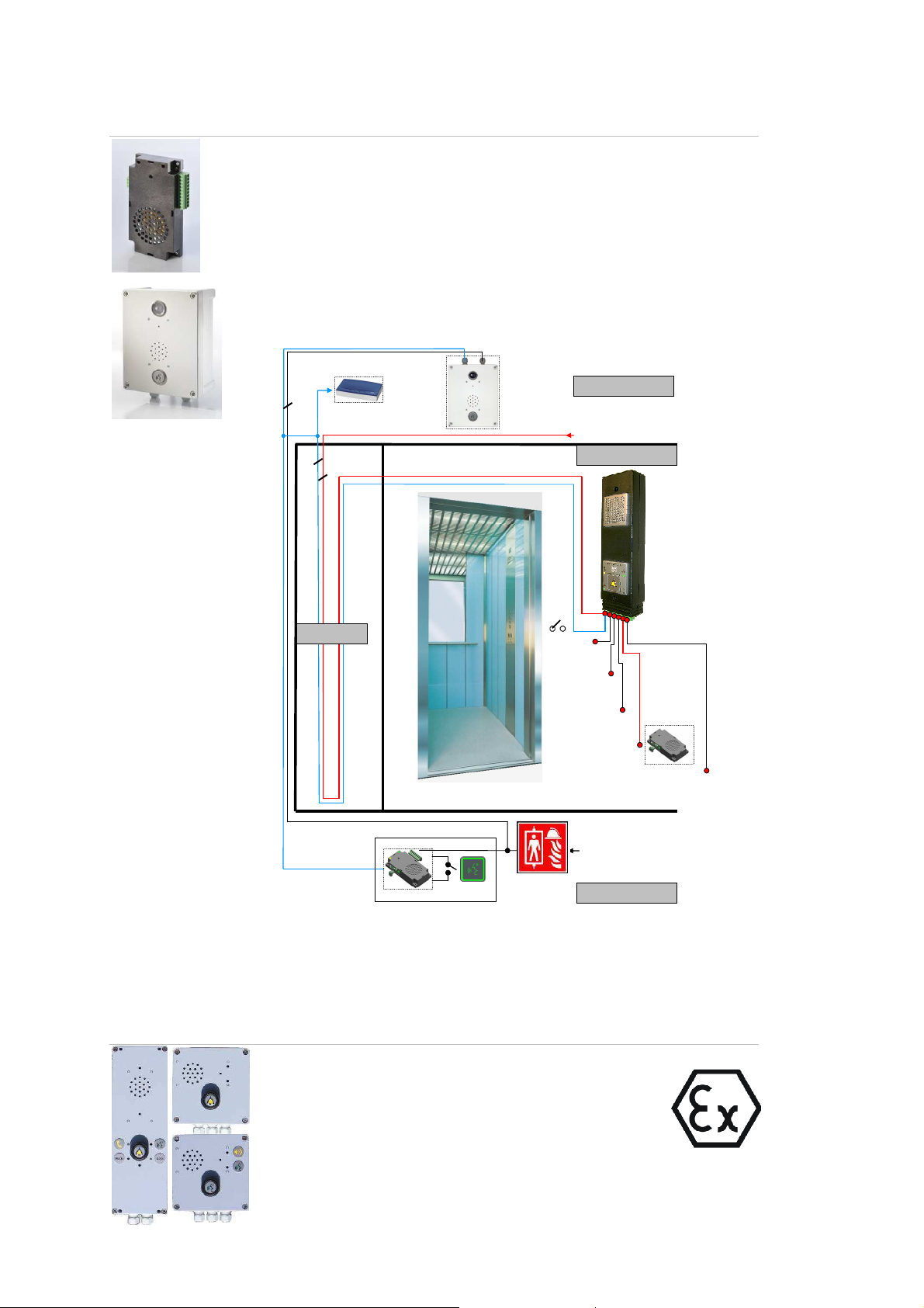
Remote-unit EA-LMK72B-WG: Fire brig ade solution accordi ng to EN 81-72 with EXICALL® EN70MR
The remote-unit gives immediate access to the main-units E XICALL®
EN70MR over a two wire connecti on (max. wire resistance 15 Ohm). Up to
two remote-units can be connected to a main-unit EXICALL® E N70MR.
Supply voltage: 8 – 35 V DC
Order-No. 118.0202B (EA-FWS-Set)
Order-No. 118.0212B (EA-FWS-IP-B ox-Set)
mounted in protective housing (IP54)
with “Talk”-button and display
Special manual available for this application
Modem
Maschinenraum
Telefonleitung / Amt
2
2
Kabine
ATEX-Application
Schacht
Externe
Notruftaste
Missbrauchsunterdrückung
Stromversorgung
10..35V DC
notstromgepuffert!
Optionale zweite
Sprechstelle: EA-LMK
System-Kontakt
Anbindung an ein Gebäudeleitsystem
(gefilterter Alarm)
Anschluss „Hilfe kommt“ Anzeige
Feuerwehrmodus:
Speisung: 8 - 35V DC
Feuerwehr
Functional description:
Key switch activates fire brigade mode.
Standby: Microphone in the cabin is active (Speak); Machine room and
fire brigade entry are in listening mode.
If “Speak” -Button is pressed the microphone of this location is active
(Speak) and the other locations are in listening mode.
Special manual available for this application
Main-Unit EXICALL® EN70-ATEX Order-No.121.5350
Sub-unit LMK-ATEX Order-No.121.0330
Remote-unit LMK72B-ATEX Order-No.121.0340
II 3G Ex nA nL IIC T6
II 3D Ex tD A22 IP64 T45°C
Ta: 0 °C ... +40°C
Supply voltage: 10 - 27 V DC 2 or 4W
SEV 09 ATEX 0141 X
38

Specifications
Supply voltage
Voltage range 10 – 35 V DC / 8 – 25 V AC
Maximum power EXICALL EN 70MR : max. 4 W
Safety r eg ul at ions
Standard EN 60950/EN 41003
Input-/ Ou tp ut
Inputs (S1-S4) active: 10 V - 40 V AC/DC in-active: < 3 V
NO contacts (K1/K3) max. 4 A/50 V AC/DC
NC contact (K2) max. 100 mA/50 V AC/DC
Environmental conditions
Temperature 0 ° to 40 °C
Humidity 20 % - 70 % relative humidity, noncondensing
Housing
Dimension 80 x 275 x 41 mm (W x H x T)
Weight ca. 500 g
Approvals
European R&TTE Directive 1999 /5/EC of 0 9.Marc h 1999
Te le phone line
Type a,b (analogue)
Equivalent circuit
EXICALL EN70-ATEX: max. 4 W
EXICALL EN70: max. 3 W
820 Ohm 220 Ohm
a b
Dialling mode DTMF
115 nF
39

Declaration of Conformity
De claration of Conformity
According to the R&TTE Directive 1999/5/EC of 09.March 1999
Manufacturer’s Name: Leitronic AG
Manufacturer’s Address: Engeloostrasse 16
CH-5621 Zufikon, Switzerland
declares that the product
Product Name: EXICALL® EN70
Model Number: EXI-EN70
E XI-E N70MR
E XI-E N70-ATEX
conforms to the following product specifications:
Safety (R&TTE, Article 3.1a): EN 60950: 1992+A1+A2+A3+A4
EMC (R&TTE, Article 3.1b): EN 50081-1, 1992
E N 50 08 2-1, 199 7 Class B
Telephone: CTR21 as specified in Council Decision
9 8/482/ EC
Supplementary Information
The product herewith complies with the requirements of the following
Directives and carries the CE marking accordingly:
the EMC directive 89/336/EWG
the Low Voltage Directive 93/68/EEC
Zufikon, 1. Juli 2009 Silvan Tognella
40
 Loading...