

Exi HALO Installation And Operation Manual

Installation and Operations Manual
© Copyright 1999, EXI Wireless Systems Inc. All rights reserved.
March 2000
Revision 2.0

EXI HALO Installation & Operation Manual 981-000003-000
Table of Contents
1. LIMITED WARRANTY..............................................................................................................................4
2. RECORD OF CHANGES............................................................................................................................6
3. FCC REGULATIONS.................................................................................................................................. 7
4. INTRODUCTION........................................................................................................................................8
4.1. ABOUT HALO INFANT PROTECTION SYSTEM............................................................................................. 8
4.2. SYSTEM COMPONENTS ............................................................................................................................. 9
4.2.1. Door Control Package (Networked) – SR2C01N.............................................................................. 9
4.2.2. Elevator Package (Networked) – SR2L01N...................................................................................... 9
4.2.3. HALO Receiver Package (Networked) - SR2R01N ......................................................................... 10
4.2.4. Power Supply................................................................................................................................ 10
4.2.5. HALO Console.............................................................................................................................. 11
5. INSTALLATION .......................................................................................................................................12
5.1. OVERVIEW TO INSTALLING THE HALO SYSTEM ..................................................................................... 12
5.2. SYSTEM WIRING............................................................................................................................... 12
5.2.1. Cabling Type................................................................................................................................. 13
5.3. SYSTEM CONNECTION .................................................................................................................... 14
5.4. DOOR CONTROL ............................................................................................................................... 15
5.5. LOCATION FOR SRA EXCITER ANTENNAS................................................................................... 15
5.6. LOCATING THE RECEIVER ANTENNA .......................................................................................... 17
5.7. FINALIZE CONTROLLER INSTALLATION ..................................................................................... 18
5.8. INSTALLING RECEIVERS ................................................................................................................. 20
5.8.1. Threshold Switch........................................................................................................................... 21
5.9. RS-485 INTERFACE MODULE (RIM)....................................................................................................... 22
5.9.1. RIM LED Status ............................................................................................................................ 22
5.10. INSTALLING ELEVATOR CONTROLLERS.................................................................................. 23
5.10.1. CONTROLLER CABINET INSTALLATION................................................................................... 24
5.10.2. LOCATION FOR SRA-E EXCITER ANTENNAS............................................................................ 25
5.10.3. Elevator Receive (RX) Antenna......................................................................................................26
5.10.4. Audible Alarm Module................................................................................................................... 26
5.10.5. Keypad.......................................................................................................................................... 26
5.10.6. “Door not Closed” Contact........................................................................................................... 27
5.10.7. Door Control and Fire Alarm Supervision..................................................................................... 27
5.10.8. System Adjustment and Testing...................................................................................................... 28
5.11. SYSTEM GROUNDING CONSIDERATIONS................................................................................. 28
6. PC NETWORKED INSTALLATION....................................................................................................... 29
7. THEORY OF OPERATION...................................................................................................................... 31
7.1. TAG COMMUNICATIONS......................................................................................................................... 31
7.2. HALO SYSTEM COMMUNICATIONS........................................................................................................31
7.3. HALO CONTROLLER ........................................................................................................................ 32
7.4. KEYPAD.............................................................................................................................................. 33
7.5. HALO RECEIVER............................................................................................................................... 35
7.6. ELEVATOR CONTROLLER............................................................................................................... 35
7.6.1. Pre-Alarm..................................................................................................................................... 35
7.6.2. Full-Alarm .................................................................................................................................... 36
7.6.3. Elevator Bypass............................................................................................................................. 36
EXI Wireless Systems 2 March 2000
Revision 2.0

EXI HALO Installation & Operation Manual 981-000003-000
8. HALO CONSOLE (SINGLE STATION).................................................................................................. 37
8.1. COMPUTER DISPLAY CONVENTIONS....................................................................................................... 39
8.2. CONNECTING TO THE HOST COMPUTER .................................................................................................. 40
8.2.1. Navigating the Dealer Screens....................................................................................................... 40
8.2.2. Adding a Floor Plan ...................................................................................................................... 42
8.2.3. Adding System Devices.................................................................................................................. 43
8.2.4. Adding Tags and Users.................................................................................................................. 44
9. DKX KEYPAD PROGRAMMING ...........................................................................................................45
10. APPENDIX A - WEIGAND OUTPUT SPECIFICATION.................................................................... 46
11. APPENDIX B - ACCESSORIES............................................................................................................ 47
11.1. SELECT SOUND MODULE (SSM)................................................................................................. 47
11.2. ANN-6L SIX ZONE ANNUNCIATOR............................................................................................. 48
12. APPENDIX C - APPLICATION NOTES..............................................................................................49
12.1. HALO CONTROLLER HOOK UP WITH ANN-6L.......................................................................... 49
12.2. ANN-6L SWITCH CONFIGURATIONS................................................................................................... 50
EXI Wireless Systems 3 March 2000
Revision 2.0

EXI HALO Installation & Operation Manual 981-000003-000
1. Limited Warranty
1. Warranty: Subject to the limiting conditions set forth below, EXI Wireless Systems Inc. (“EXI”) hereby
warrants that: (a) each product, other than transponders (the “Transponders”), accompanying this warranty
(the “Product”), will be free of defects in materials and workmanship for a period (the “Product Warranty
Period”) of two years after the date of the original sale by EXI of the Product; and (b) each Transponder
accompanying this warranty will be free of defects and workmanship for a period (the “Transponder
Warranty Period”) of, in the case of a WTX-INF/WS Transponder, four years, and in the case of all other
Transponders, three years, after the date of the original sale by EXI of the Transponder.
2. Notification: If the original or any subsequent purchaser (collectively, the “Purchaser”) of the Product or
Transponder, as the case may be, discovers a defect in materials or workmanship of a Product within the
Product Warranty Period, or a Transponder within the applicable Transponder Warranty Period, the
Purchaser must, within 30 days after the date of such discovery, notify EXI of such defect, and at EXI’s
request, return the defective Product or Transponder, as case the may be, to EXI.
3. Repair or Replacement: Subject to §4, upon acceptance by EXI of responsibility for the defect, EXI will,
in its sole discretion, (a) in the case of a Product, either replace the Product, or provide the Purchaser with
replacement parts for, or repair, the same; and (b) in the case of a Transponder, replace the Transponder at
a discounted price equal to the product of: (i) the nearest whole number of months remaining in the
applicable Transponder Warranty Period; and (ii) the amount of the then monthly credit available from EXI
for the applicable Transponder. EXI’s warranty in respect of any replacement Product, part thereof, or
Transponder, as the case may be, will be for the unexpired portion of the original warranty period
applicable to the relevant Product or Transponder.
4. Exclusion: The warranty referred to in §1 is the sole warranty made by EXI with respect to its Products
and Transponders. EXI makes no other warranty or representation, express or implied, and hereby
disclaims any implied warranty of merchantability or fitness for a particular purpose, statutory or
otherwise, concerning its Products and Transponders. In addition, the warranty will not apply if EXI has
not received a fully completed warranty registration card in respect of the Product or Transponder, as the
case may be, within 30 days after the date of the original purchase from EXI of the same, or the Product or
Transponder, as the case may be, or any part thereof: (a) is damaged by misuse, accident, negligence,
lightning, power surge, brown-out, or leaking, damaged or inoperative batteries, or failure to maintain the
Product or Transponder as specified or required by EXI; (b) is damaged by modifications, alterations or
attachments thereto which are not authorized by EXI; (c) is installed, operated or repaired contrary to the
instructions of EXI; (d) is opened, modified or disassembled in any way without EXI’s consent; or (d) is
used in combination with items, articles or materials not authorized by EXI.
5. Limitation: EXI will only be liable to the Purchaser for direct damages suffered by the Purchaser up to a
maximum amount equal to the total amount of the purchase price actually paid by the Purchaser to EXI for
the Product or Transponder, as the case may be. Specifically, EXI will not be liable for: (a) any special,
indirect or consequential damage, including lost profits, lost revenues, failure to realize expected savings,
or other commercial or economic losses of any kind, even if EXI has been advised of the possibility of such
damage; (b) any loss or damage to any property or for any personal injury or economic loss or damage
caused by the connection of the Product or Transponder, as applicable, to other devices or systems; (c) any
damage or injury arising from or as a result of, misuse, abuse or incorrect installation, integration or
operation of the Product or Transponder, as applicable, by persons not authorized by EXI; or (d) any defect
in any batteries added to or used in conjunction with the Product or Transponder.
EXI Wireless Systems 4 March 2000
Revision 2.0

EXI HALO Installation & Operation Manual 981-000003-000
6. Product Limitation: The Purchaser (a) acknowledges that (i) the Products and the Transponders are not,
nor can they be, guaranteed to prevent wandering patients, infant abductions, theft or any other event for
which they were purchased, (ii) the Products and Transponders are only intended to provide additional
safeguards to assist in the prevention of events such as those described in §(i), and (b) understands fully the
foregoing limitations concerning the Products and Transponders, including EXI’s limitation on liability
described in §5, and agrees to warn, and obtain acknowledgements from, all users thereof of the same.
7. No Additional Warranties: The terms and conditions herein contain all the warranties and
representations concerning EXI’s Products and Transponders and supersede all previous negotiations,
understandings, communications, representations, warranties and agreements, whether verbal or written,
concerning the Products and Transponders.
8. Deemed Acceptance: The installation or use of the Product or Transponder by or at the direction of the
Purchaser will be deemed as an acceptance by the Purchaser of the terms hereof.
9. Governing Law: The warranty herein will be governed by the domestic laws of the Province of British
Columbia, Canada and the Purchaser hereby attorns to the exclusive jurisdiction of the laws of British
Columbia. The provisions of the United Nations Convention on Contracts for the International Sale of
Goods is hereby excluded.
EXI Wireless Systems 5 March 2000
Revision 2.0

EXI HALO Installation & Operation Manual 981-000003-000
2. Record of Changes
October 1999 Combined HALO Installation & Operating Manual and Elevator Manual.
March 2000 Added Cabling types and Threshold / RX Sensitivity Switch Adjust.
EXI Wireless Systems 6 March 2000
Revision 2.0
EXI HALO Installation & Operation Manual 981-000003-000
*
*
*
Made in Canada
3. FCC Regulations
This device complies with Part 15 of the FCC Rules. Operation is subject to the following two conditions: (1) This
device may not cause harmful interference, and (2) This device must accept any interference received, including
interference that may cause undesired operation.
This equipment has been tested and found to comply with the limits for Class B Digital Device, pursuant to Part 15
of the FCC Rules. These limits are designed to provide reasonable protection against harmful interference in a
residential installation. This equipment generates and can radiate radio frequency energy and, if not installed and
used in accordance with the instructions, may cause harmful interference to radio communications. However, there
is no guarantee that interference will not occur in a particular installation. If this equipment does cause harmful
interference to radio or television reception, which can be determined by turning the equipment off and on, the user
is encouraged to try to correct the interference by one or more of the following measures.
• Reorient or relocate the receiving antenna
• Increase the separation between the equipment and receiver
• Connect the equipment into an outlet on a circuit different from that to which the receiver is connected
• Consult the dealer or an experienced radio/TV technician for help
Any changes or modifications not expressly approved by the party responsible for compliance could void the user’s
authority to operate the equipment.
EXI Wireless Systems Model No.: Patient Tag
CANADA: 287710217261A FCC ID: HE7 PTG
This device complies with Part 15 of the FCC Rules. Operation is
subject to the following two rules: (1) This device may not cause harmful
interference, and (2) This device must accept any interference received,
including interference that may cause undesired operation.
Made in Canada
EXI Wireless Systems Model No.: Halo Infant/ECO tag
CANADA: TBD FCC ID: HE7 ETG
This device complies with Part 15 of the FCC Rules. Operation is
subject to the following two rules: (1) This device may not cause harmful
interference, and (2) This device must accept any interference received,
including interference that may cause undesired operation.
Made in Canada
EXI Wireless Systems Model No.: Halo Asset tag
CANADA: TBD FCC ID: HE7 ATG
This device complies with Part 15 of the FCC Rules. Operation is
subject to the following two rules: (1) This device may not cause harmful
interference, and (2) This device must accept any interference received,
including interference that may cause undesired operation.
EXI Wireless Systems 7 March 2000
Revision 2.0

EXI HALO Installation & Operation Manual 981-000003-000
SYSTEM MAINTENANCE SHOULD INCLUDE THE FOLLOWING STEPS:
4. INTRODUCTION
This manual serves as a guide for Installers of the HALO system. The major components of the system are
described, as well as the system’s intended functionality, so as to gain familiarity with its operation prior to
installation. In order to successfully install and commission the system, it is absolutely critical to
understand the capabilities of the system and its components prior to installation.
4.1. About Halo Infant Protection System
Halo is a premium infant protection system. Halo works in conjunction with the EXI P-tag patient
transponder that is capable of sensing if it has been removed from the infant. Halo is an electronic system,
which, in conjunction with staff diligence, creates a secure perimeter to deter infant abductions.
The function of the HALO system is to monitor areas within a building for the presence of HALO Tags. A
Tag is sensed when it either enters an RF Field that is set up using the EXI HALO Controller (referred to as
a Tag in Field or TIF), or when the Tag initiates an alarm signal (referred to as Tag Initiated
Communications, or TIC).
HALO is designed to assist staff in providing a higher degree of safety for patients. It is not intended as
the sole means of protection in preventing a wanderer or infant from leaving the premises. Regular
checks to verify that your HALO system is operational is highly recommended.
All Tags should be checked for physical damage after each cleaning, disinfecting or sterilization
procedure.
Each Tag should be tested for correct operation before being attached to an infant. The HALO
software prompts for testing of Tags prior to their deployment. Please refer to the appropriate
section in this manual for the instructions.
The warranty on Tags is 3 years, and the batteries within the Tags are expected to last in excess of
the warranty period depending on the usage pattern. Do not leave Tags in the detection field for
long periods of time, and store them in the foil bags supplied. Failure to do so will result in false
alarms, and will reduce battery life.
Set up a regular system check schedule to verify that the Controllers, Receivers and Tags are
operational. Controllers should have the “Ready” light illuminated to show that they are powered.
Check the operation of the Controller daily by starting a bypass or triggering an alarm using a Tag
to ensure that it is fully operational and protecting the egress point where it is located.
Check each Receiver on a regular basis to ensure that it can receive signals from Tags in the “Off
Body” condition. Failure to regularly check for this operation may lead to failure to detect a Tag
that is removed from an infant, and therefore compromising protection for the infant.
Whenever you see an infant who is a patient, look for the Tag on this infant to verify that it is still
securely attached. This may require special knowledge as to the placement of the Tag.
Conduct frequent back-ups of Activity Logs for future reference.
EXI Wireless Systems 8 March 2000
Revision 2.0
EXI HALO Installation & Operation Manual 981-000003-000
4.2. System Components
This section describes the various system components required to complete the installation of the HALO
system.
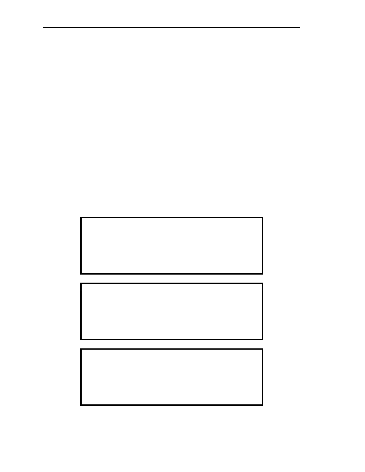
4.2.1. Door Control Package (Networked) – SR2C01N
Figure 1 - Halo Controller Package
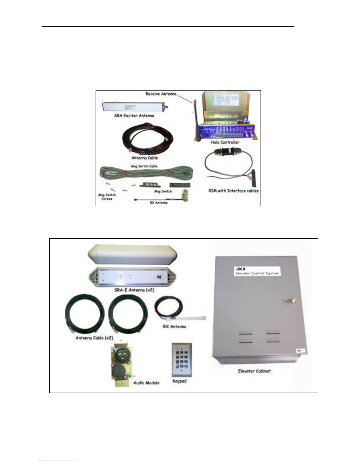
4.2.2. Elevator Package (Networked) – SR2L01N
EXI Wireless Systems 9 March 2000
Figure 2 - HALO Elevator Controller Package
Revision 2.0
EXI HALO Installation & Operation Manual 981-000003-000
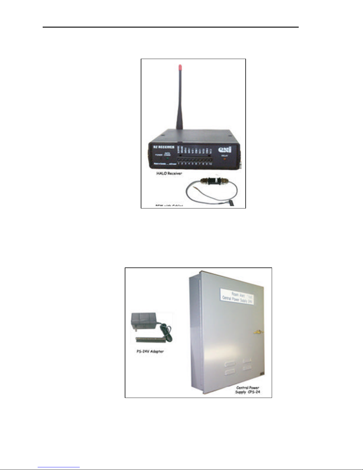
4.2.3. HALO Receiver Package (Networked) - SR2R01N
Figure 3 - HALO Receiver Package
4.2.4. Power Supply
Individual power supply adapters Model # AR2PS01-024 may be used for each of the Door Control
Packages and the Receivers. Alternatively, a Central Power Supply Model # AGECP01-624 has 6
independent inputs, each of which can power one Controller or two Receivers. The CPS may be purchased
with a battery back-up option, which is highly recommended.
EXI Wireless Systems 10 March 2000
Figure 4 – Power Supply choices
Revision 2.0
EXI HALO Installation & Operation Manual 981-000003-000
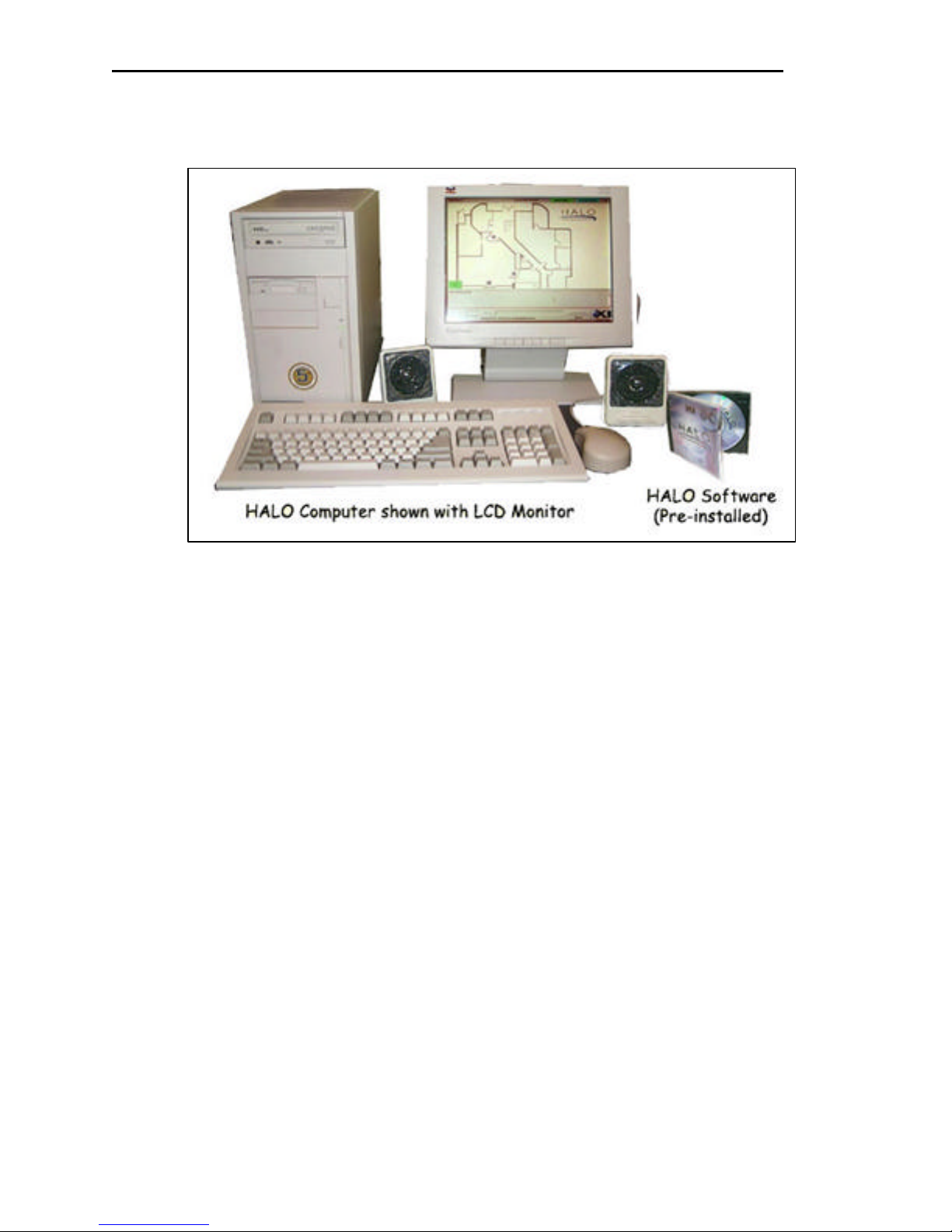
4.2.5. HALO Console
Figure 5 - HALO Computer Package
EXI Wireless Systems 11 March 2000
Revision 2.0
EXI HALO Installation & Operation Manual 981-000003-000
5. Installation
5.1. Overview to Installing the HALO System
EXI HALO is designed to provide extended periods of reliable service. Once installed correctly, the system
does not require tuning or adjustments, and it should provide exemplary service unless the position of its
components is subsequently disturbed, the physical environment is altered as in a renovation, or a very strong
noise source is introduced into the environment.
Elevator
Penthouse
HALO
RS-485
Repeater
Controller
HALO
Elevator
Elevator
Travel
Cable
Keypad
ELEVATOR
SRA-E Exciter
Antennae (2)
6 Lines + GND
Receiver
ELECTRICAL
ROOM
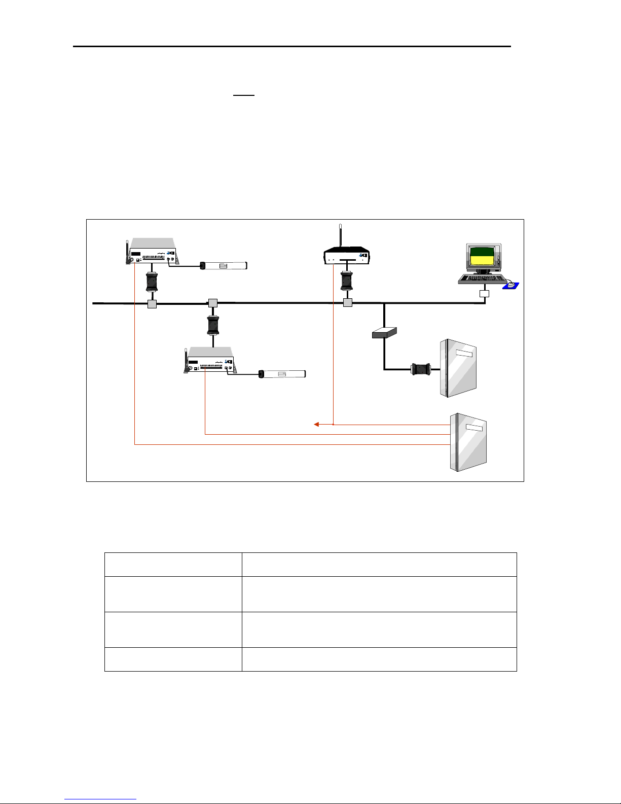
5.2. SYSTEM WIRING
HALO
Console
HALO Network
"Bus" (Series)
Configuration
RIM
Power Distribution
HALO
Transponders
CPS-24
Central Power
Supply
Figure 6 – Typical HALO System Installation
Keypad
SRA Exciter
Antenna
HALO
Controller
Mag Switch
MagLock
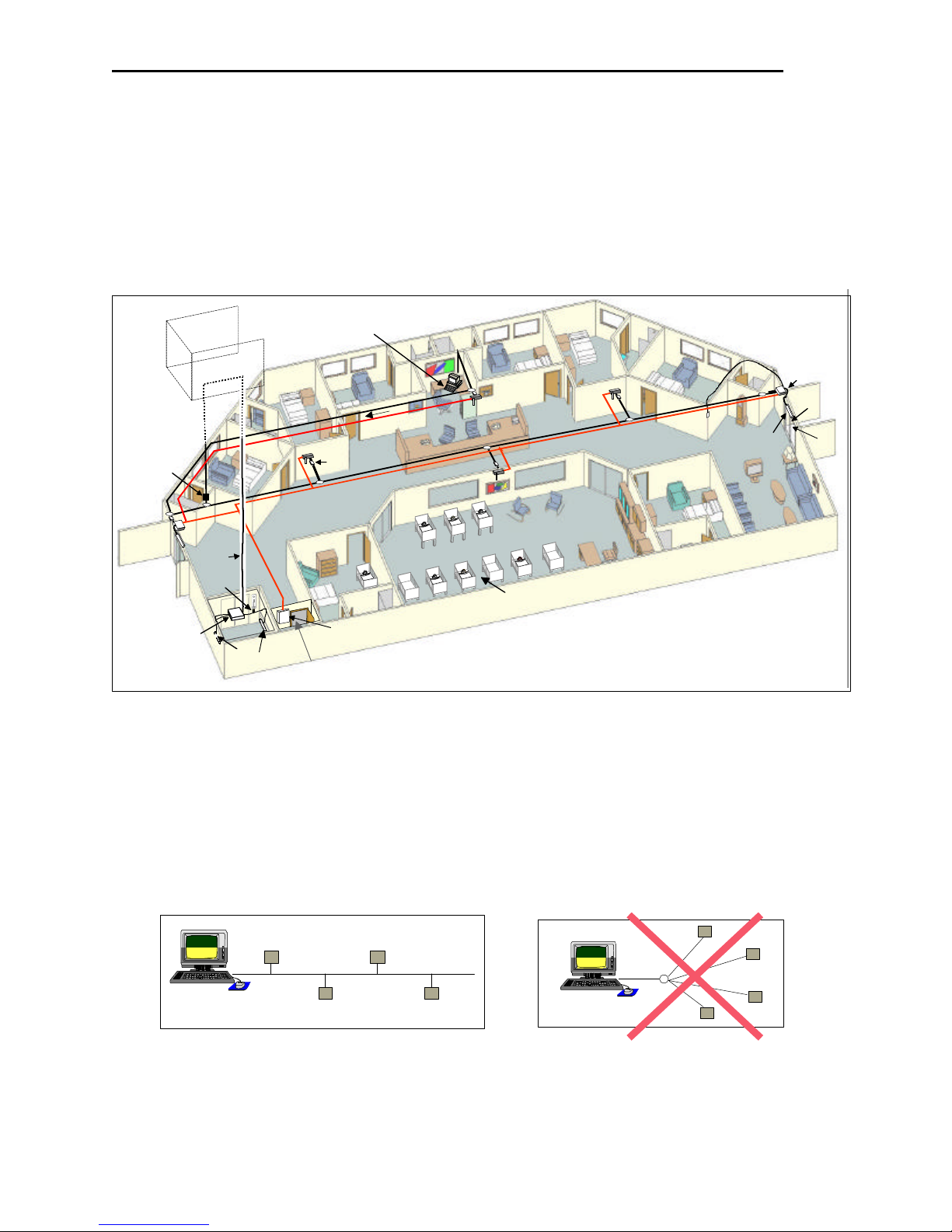
The HALO network is based on the RS-485 electrical interface standard, which is 2-wire multi-node bus.
The EXI HALO elements are designed such that many more than the RS-485 limit of 32 Drivers and 32
Receivers can be co-exist on the same network. The baud rate used in the HALO system is 57,600 bps, and
therefore in order to avoid data corruption it is important to ensure that a clean signal is always present.
Using the right type of cable, network topology, and not exceeding total cable length are critical factors in
ensuring that the system will operate reliably.
Figure 7 - "Bus" Topology Figure 8 - "Star” Topology
EXI Wireless Systems 12 March 2000
Revision 2.0
EXI HALO Installation & Operation Manual 981-000003-000
Cable capacitance is a large factor in determining the quality of the signal on the network, and EXI recommends that
cables with capacitance of greater than 15 pf per foot should be avoided. The network should be constructed using a
“multi-drop bus” type topology, avoiding any “star” type configuration. The system is designed to operate with up to
4,000 ft of cable with the recommended topology and cable. The total cable length varies depending upon the cable
capacitance and nominal impedance, topology, and number of devices on the network. If the estimated total cable
length is greater than 4,000 ft, a RS-485 Repeater will be required to ensure that the system works reliably, or works
at all. It is also recommended that a Repeater be used to isolate HALO Elevator Controllers from the main system to
minimize noise pick-up and loading of the system. Cables used in Elevator shafts should be stranded and not solid,
and should be resilient enough to withstand the continuous flexing that it will experience for many years in the
elevator shaft.
Whip
Antenna
Controller 1
FCC ID# HE7MAX
+24V DC Input
System Ground
+12V Ou 200 ma
System Ground
Weigand 0/Data
Weigand 1/Gnd
System Ground
MagOut 24V 200 ma
Door Switch In
Alarm In
RECEIVE
ANTENNA
RBC
Power
1 2 3 4 5 6 7 8 9 10 11 12 13 14 15 16 17 18 19 20
OFF ON
Made in Canada . . with care
TAP
Relay #1 Relay #2
System Ground
Unlock In
Override In
Strobe In
N.O
COM
N.C.
N.O
COM
N.C
RIM
Whip
Antenna
Whip
Antenna
by
TRANSMIT OUTPUT
SEA #1 SEA #2
Controller
Exciter
Antenna
SERIAL NO>
1118
MODEL NO.
SEA-M
PRODUCT
ROAM II/TAGRRR
Made in Canada
Winnipeg, Manitoba (204) 788-1696
EXI ELECTRONIC SYSTEMS
R2 RECEIVER
POWER
Made in Canada . . with care
DATA
COMM.
Receiver 1
12/24 VDC
GROUND
DATA 0
DATA 1
N/O 1
COM 1
N/C 1
N/O 2
COM 2
N/C 2
1 2 3 4 5 6 7 8 9 10
RELAY
RIM
RIM
FCC ID# HE7MAX
RECEIVE
ANTENNA
Made in Canada . . with care
+24V DC Input
System Ground
RBC
Power
1 2 3 4 5 6 7 8 9 10 11 12 13 14 15 16 17 18 19 20
OFF ON
TAP
RS485 Bus
TAP
by
Relay #1 Relay #2
+12V Ou 200 ma
System Ground
Weigand 0/Data
Weigand 1/Gnd
System Ground
MagOut 24V 200 ma
Door Switch In
System Ground
Unlock In
Override In
Strobe In
N.O
COM
N.C.
N.O
COM
N.C
Alarm In
TRANSMIT OUTPUT
SEA #1 SEA #2
Controller
Exciter
Antenna
SERIAL NO>
1118
MODEL NO.
SEA-M
PRODUCT
ROAM II/TAGRRR
Made in Canada
Winnipeg, Manitoba (204) 788-1696
EXI ELECTRONIC SYSTEMS
RS-485
Repeater
HALO Network
Elevator Controller
RIM
PC
Terminator
Elevator Control System
CPS-24
To 2nd Receiver
(2 Receivers per output)
24V Output 1
24V Output 2
Central Power Supply
Central Power Supply
24V Output 3
Figure 9 - Typical HALO Configuration
5.2.1. Cabling Type
Power Cable
RS485 Network Cable
Ethernet Network Cable
Elevator Travel Cable
EXI Wireless Systems 13 March 2000
2-conductor, 18-gauge, shielded or unshielded.
2-pair, unshielded twisted pair, 24-gauge, maximum capacitance
15pF per feet.
10 Base –T cabling
CAT 5 – 4-pair, unshielded twisted pair.
3-conductor, shielded, stranded, low capacitance travel cable.
Revision 2.0
EXI HALO Installation & Operation Manual 981-000003-000
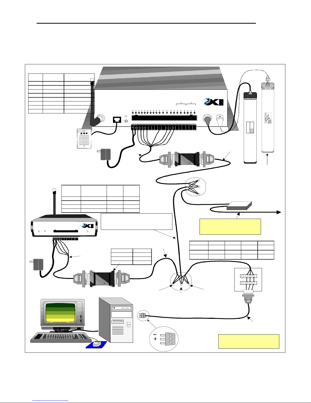
5.3. SYSTEM CONNECTION
The figure below shows the details of connecting the various system components together for the HALO
system.
Halo Controller Connector Pin-Out
Pin# Wire
3 Brown +12/24 V
4 Green System GND
5 Black Weigand 0/Data
6 Blue Weigand 1/Data
10 White Alarm In
12 Red Unlock In
13 Yellow Override In
14 Gray Strobe In
Color
R2 RECEIVER
POWER
Made in Canada . . with care
Optional
PS-24
Power
Supply
DATA
COMM.
12/24 VDC
GROUND
1 2 3 4 5 6 7 8 9 10
Function
FCC ID# HE7MAX
R2 Controller
RECEIVE
ANTENNA
Made in Canada . . with care
1 2 3
4 5 6
DKX
7 8 9
0
#
*
Keypad
Optional
PS-24
Power
Supply
Halo Receiver Connector Pin-Out
R2
Receiver
Pin
1 +12/24V Brown 14
2 System GND Green 7
3 Data 0 Black 20
4 Data 1 Blue 22
DATA 0
DATA 1
N/O 1
COM 1
N/C 1
N/O 2
Blk
Blu
Grn
Brn
Function Wire
COM 2
N/C 2
RELAY
Factory
Wired
RBC
Color
RS-485 Shielded Cable, 24 AWG
Maximum Capacitance 15 pf per foot
Example: Electro Cables FT-4 Part #5302452
Daisy Chain (Series) Configuration as much as
possible.
9 or 12 RS +
7 GND
22 or 25 RS -
+24V DC Input
System Ground
+12V Out 200 ma
Power
OFF ON
Factory
Wired
System Ground
1 2 3 4 5 6 7 8 9 10 11 12 13 14 15 16 17 18 19 20
Blk
Brn
Grn
DB 25
RIM Pin-Out
Pin # Function
Weigand 0/Data
Weigand 1/Gnd
System Ground
Blu
Whi
Alarm In
MagOut 24V 200 ma
Door Switch In
Red
Weigand
Factory
Supplied
System Ground
Unlock In
Yel
n
a
r
O
Relay #1 Relay #2
Override In
Strobe In
N.O
y
a
r
G
r
o
e
g
by
COM
N.C.
N.O
COM
N.C
TRANSMIT OUTPUT
RIM
TAP
RS-
RS+
RS-485 3-Conductor Cable Code
(All have same function, but 4 versions of wire color)
Function Type 1 Type 2 Type 3 Type 4
RS +
GND Green Blue White Green
RS
-
SEA #2
SEA #1
Controller
Factory
Supplied
RS-485
GND
Caution: Ensure appropriate
stranded cables are used for
Elevator Shafts due to the
continuous flexing they will
have to endure!
Optional RS-485 Repeater
(Required for total cable length
of greater than 4,000 ft, and
highly recommended for isolation
of Halo Elevator Controller)
RS-485
Repeater
Yellow Brown Black Red
White Red Red Black
ROAM II/TAGRRR
SEA-M
1118
Made in Canada
EXI ELECTRONIC SYSTEMS
Winnipeg, Manitoba (204) 788-1696
PRODUCT
MODEL NO.
SERIAL NO>
Optional, to
Enhance
Coverage
Elevator System or
other devices
Weigand
RIM
EXI Wireless Systems 14 March 2000
RS-485
R2 TAP
RS
+
RS-485 Connector (To Halo
NetworkController Output)
RS+
GND
Gnd
Enlarged
Com
Figure 10 - Detailed System Diagram
View
RS-
PC Terminator
Box
RS
-
PC to
Network Cable
NOTE: Check all network
wiring before connecting
to the PC.
Revision 2.0
DB9
Factory
Supplied
EXI HALO Installation & Operation Manual 981-000003-000
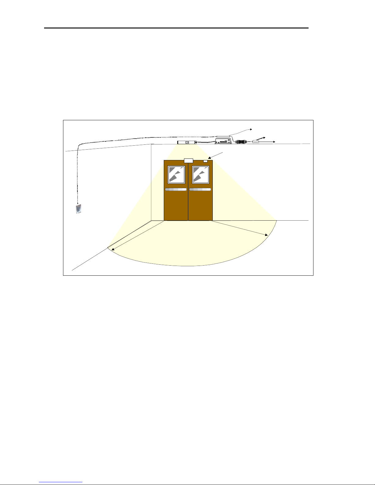
5.4. DOOR CONTROL
The controller chassis may be horizontally or vertically mounted, on a wall, ceiling or shelf and should be
mounted so that the front face panel is easily accessible. Since it is preferable to leave the RX antenna attached
directly to the controller, the exact location of the controller will affect the reception of the tags and should
only be finalized after setting up the field. The RX antenna should be positioned on a vertical plane for
maximum performance.
Keypad
Controller
FCC ID# HE7MAX
EXI ELECTRONIC SYSTEMS
Winnipeg, Manitoba (204) 788-1696
Made in Canada
PRODUCT
ROAM II/TAGRRR
MODEL NO.
SEA-M
SERIAL NO>
1118
Roam II & Tagrrr
RECEIVE
ANTENNA
Made in Canada . . with care
Exciter Antenna
Mag-Lock
0
1
D
e
t
e
c
t
i
o
n
~
a
r
e
A
Figure 11 – Door Coverage
HALO
RIM
by
Relay #1Relay #2
+24V DC Input
System Ground
+12V Ou 200 ma
System Ground
Weigand 0/Data
Weigand 1/Gnd
System Ground
MagOut 24V 200 ma
Door Switch In
System Ground
Unlock In
Override In
Strobe In
N.O
COM
N.C.
N.O
COM
N.C
Alarm In
TRANSMIT OUTPUT
SEA #1 SEA #2
RBC
Power
1 2 3 4 5 6 7 8 9 10 11 12 13 14 15 16 17 18 19 20
OFF ON
Controller
Door Sense
Magnetic Switch
'
Power
TAP
To other
Devices
To Computer
• Mount the Keypad about 10’ away from door so that it can be used before entering the detection
field.
• Maglock release should be hooked up to an unused auxiliary normally open contact from Fire
Alarm Panel.
5.5. LOCATION FOR SRA EXCITER ANTENNAS
One of the most important aspect of the entire installation is the correct positioning of the SRA Exciter
Antenna. The Antenna may be installed:
Ø above the doorway, laid flat on the dropped ceiling tile.
Ø dropped inside a wall cavity 4’ above the floor.
Ø on the side wall along the hallway 4’ above the floor.
Each field needs to be fully tested to ensure adequate coverage of the protected area.
EXI Wireless Systems 15 March 2000
Revision 2.0
 Loading...