

Exi eAC Transceiver Installation Manual
EAC Transceiver: Installation Guide
C
D
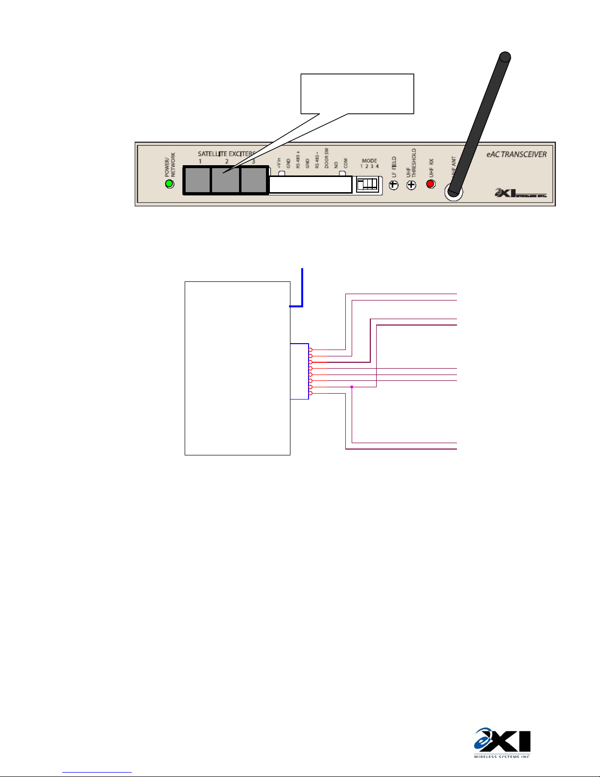
CONNECTIONS
1
NOTE: 307.2 kHz EXCITER
INDUCTORS MOUNTED
ON PC BOARD
EAC TRANSCEIVER
COM
NO
DOOR SW
RS485 -
GND
RS485 +
GND
+Vin
SATELLITE EXTENSION
1 2 3 NOT USED ON
THIS PRODUCT
433.92 MHz RECEIVE
ANTENNA
8
7
6
5
4
3
2
1
USER DEFINED
RELAY CONTACTS
3A/30VDC RESITIVE
FROM DOOR SWIT
RS485 NETWORK
LISTED CAT 5E
24VDC 300MA
250VA PWR LIMITE
eAC System components are designed to meet the requirements for Class 2 circuits operating from a
non-hazardous secondary power source limited to 240 VA. Cabling materials must be selected for the
installation environment in accordance with the applicable jurisdictional codes.
SELV SUPPLY
INSTALLATION
2
The Controller chassis may be horizontally or vertically mounted on a wall, ceiling, or shelf as long as the
MOUNTING INSTRUCTIONS
front face panel is easily accessible. The RX antenna should be positioned on a vertical plane for
maximum performance.
The detection field radiates from two internal orthogonal ferrite cored inductors. The field must fill the
area in front of the door all the way to the floor so that no Tag can reach the door without being detected.
981-000046-000R1.05

EAC Transceiver: Installation Guide
TUNING & ADJUSTMENT
3
An eXI RF Test Tag is used for adjustment of the Receiver Threshold and LF
Field Strength
Refer to eAC HUB network installation instructions for network cabling requirements.
The UHF Threshold control may be adjusted to increase or reduce the range of detection of the UHF
Adjust the LF Field for a compromise between maximum desired tag detection range and the potential to
NETWORK STATUS
NETWORK STATUS INDICATOR LED CONDITION
OFF No power to Receiver
Solid GREEN Power supplied; Network normal
Flashing GREEN Power supplied: Network Communication Failure
RECEIVER SENSITIVITY
transmission of the Tags. Threshold adjustment removes some of the background noise, and reduces
interference from Tags not within the field of the Transceiver.
Initially decrease the threshold (CCW) until the UHF RX indicator flashes occasionally. This will establish a
threshold sensitivity to background noise at the door site. Using the RF Test Tag in the keyed mode,
reduce the receiver sensitivity (increase threshold CW) until the RX indicator becomes intermittent at 25
to 30 feet. Reduce the threshold slightly and walk the tag around the area of coverage to check for
consistent UHF reception.
LF FIELD ADJUSTMENT
excite tags in adjacent rooms or floors. Note that the LF field tends to be omni-directional. Starting with
the field adjustment at maximum (full CW), walk the RF Test Tag around the area of desired protection.
Reduce the field until inconsistent tag identification occurs in parts of the coverage. (The UHF Threshold
adjustment should be increased to check that the eLink is not being limited by the UHF link.) Increase
the field strength in small increments until consistent detection results within the desired area of
detection.
FCC Regulations
This device complies with Part 15 of the FCC Rules. Operation is subject to the following two conditions:
(1) This device may not cause harmful interference, and (2) This device must accept any interference
received, including interference that may cause undesired operation.
This equipment has been tested and found to comply with the limits for Class B Digital Device, pursuant
to Part 15 of the FCC Rules. These limits are designed to provide reasonable protection against harmful
interference in a residential installation. This equipment generates and can radiate radio frequency
energy and, if not installed and used in accordance with the instructions, may cause harmful interference
to radio communications. However, there is no guarantee that interference will not occur in a particular
installation. If this equipment does cause harmful interference to radio or television reception, which can
be determined by turning the equipment off and on, the user is encouraged to try to correct the
interference by one or more of the following measures.
• Reorient or relocate the receiving antenna
• Increase the separation between the equipment and Receiver
• Connect the equipment into an outlet on a circuit different from that to which the Receiver is
connected
• Consult the dealer or an experienced radio/TV technician for help
Any changes or modifications not expressly approved by the party responsible for compliance could void
the user’s authority to operate the equipment.
981-000046-000R1.00
 Loading...