

Exhausto VEX260H Original Instructions Manual
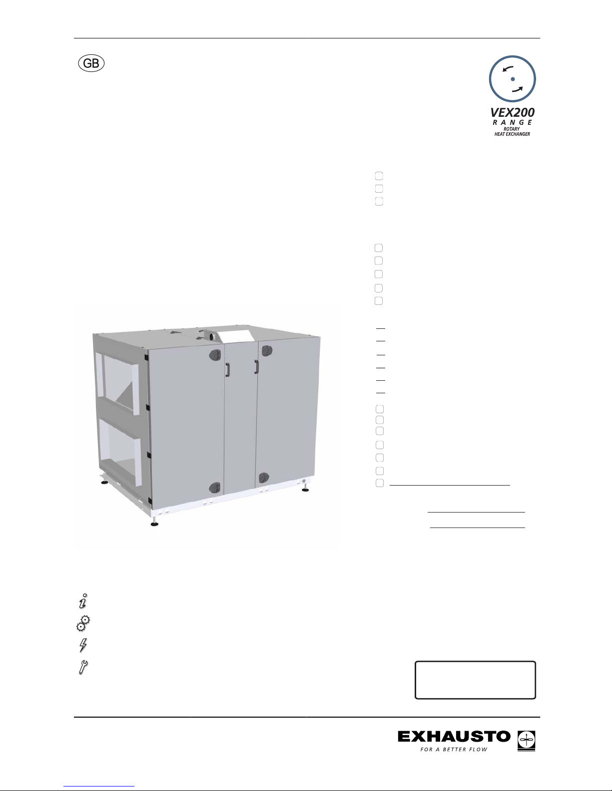
VEX260H
with rotary heat exchanger and EXact control system
Product information........................................Chapter 1 + 6
Mechanical assembly.....................................Chapter 2 + 3
Electrical installation.......................................Chapter 4
Maintenance...................................................Chapter 5
MIO-TS-DUCT temperature sensor
MIO-TS-ROOM , temperature sensor
MIO-CO2-DUCT, CO2-sensor
MIO-RH humidity sensor
pieces, HMI control panel
pieces, MPT-DUCT constant pressure control
MXCU control for external cooling unit
pieces, MIO-PIR motion sensor
MIO-CO2-ROOM, CO2-sensor
Closing damper, LS400x80024, (LSA exhaust)
Closing damper, LS400x80024, (LSF outdoor)
Closing damper, LSR400x80024, with
spring-return (LSFR outdoor)
The following accessories are supplied
separately:
Unit supplied with (factory fitted):
Compact filter FP
pieces, Fire thermostat, BT40
pieces, Fire thermostat, BT50
pieces, Fire thermostat, BT70
Filter bag FB
HCE external heating coil (electrical)
HCW external heating coil (water)
Trim damper and blowout zone,TB260
Prod.order no.:
Sales order no.:
Original instructions
3003434-2014-04-14
VEX260_EXact
EXHAUSTO A/S
Odensevej 76
DK-5550 Langeskov
Tel. +45 65 66 12 34
Fax +45 65 66 11 10
exhausto@exhausto.dk
www.exhausto.dk
1. Product information
1.1. Model overview......................................................................................................5
Model overview..........................................................................................................5
1.2. Terms used in these instructions........................................................................7
1.3. Application.............................................................................................................8
1.4. Location requirements..........................................................................................8
1.4.1. Spatial requirements........................................................................................8
1.4.2. Requirements for underlying surface...............................................................9
1.4.3. Requirements for duct system.........................................................................9
1.5. Description...........................................................................................................10
1.5.1. The VEX unit design......................................................................................10
1.6. Principal dimensions...........................................................................................14
VEX260, V1.............................................................................................................14
VEX260, V2.............................................................................................................15
2. Handling
2.1. Unpacking............................................................................................................16
2.2. Transport..............................................................................................................16
2.2.1. Weight............................................................................................................16
2.2.2. The VEX sections' principal dimensions........................................................17
2.2.3. Internal transport with reduced weight...........................................................17
3. Mechanical assembly
3.1. Installing the unit.................................................................................................20
3.1.1. Removal and assembly instructions .............................................................20
4. Electrical installation
4.1. Electrical installation...........................................................................................23
5. Maintenance
5.1. Operating readings via the HMI panel...............................................................24
5.2. Maintenance chart...............................................................................................24
5.3. Service..................................................................................................................25
5.3.1. Filter replacement..........................................................................................25
5.3.2. Servicing and cleaning...................................................................................25
6. Technical data
6.1. Weight, corrosion class, temperature range, etc.............................................27
6.2. Compact filters.....................................................................................................29
6.3. Bag filters.............................................................................................................30
6.4. Capacity diagram.................................................................................................31
6.4.1. Unit with compact filter...................................................................................31
6.4.2. Unit with bag filter..........................................................................................32
6.5. Ordering spare parts...........................................................................................32
6.6. EC Declaration of Conformity.............................................................................33
3003434-2014-04-14
2/34

Symbols, terms and warnings
Prohibition symbol Failure to observe instructions marked with a prohibition symbol
may result in serious or fatal injury.
Danger symbol Failure to observe instructions marked with a danger symbol may
result in personal injury and/or damage to the unit.
Scope This instruction manual is for use with EXHAUSTO VEX-type air handling units.
Please refer to the product instructions regarding accessories and extra equipment.
The instructions must be fully observed to ensure personal safety and to protect the
equipment and ensure its correct operation. EXHAUSTO A/S accepts no liability for
accidents caused by equipment not used in accordance with the manual’s instructions and recommendations.
Supply air/extract
air
These instructions use the following terms as given in DS447-2013:
● Supply air (air blown in)
● Extract air (air removed)
● Outdoor air
● Exhaust air
Left/Right The term R for Right, indicates the supply air is to the right of the cooling unit, as
seen from the operating side. The term L for Left, indicates the supply air is to the
left.
Front page: Accessories
The front page of the instruction manual contains a checklist, detailing the accessories delivered with the VEX unit.
NB When retrofitting EXHAUSTO accessories, please update the checklist on the
front page.
Warnings:
Opening the unit Do not open the service doors before the supply voltage has been
disconnected at the isolation switch and the fans have stopped.
The isolation switch is positioned on the left side of the connection box on top of the unit.
3003434-2014-04-14
3/34
Prohibited The VEX unit is not to be used to transport solid particles or in
areas where there is a risk of explosive gases.
No duct connection If one or more of the spigots is not connected to a duct: Fit a
protective net to the spigots with a maximum mesh width of 20
mm (in accordance with EN294).
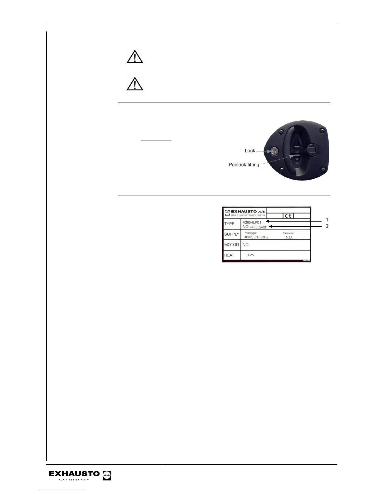
Lock the air handling unit during operation
The VEX unit must always be locked
during operation:
● Use the cylinder lock in the handle. Remember to remove the
key from the lock.
● Or use a padlock. Use the handle’s built-in padlock fixture
Information plate The VEX unit information plate
shows:
● VEX model type (1)
● Unit production no. (2)
NB: Have the production number ready at all times when contacting EXHAUSTO
A/S.
3003434-2014-04-14
4/34
1. Product information
1.1 Model overview
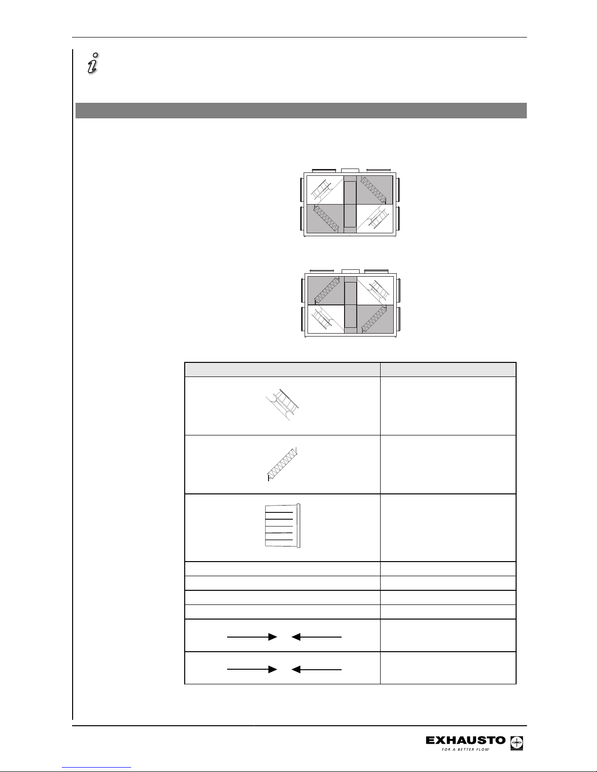
Model overview
Positioning of fan,
motor (M) and frequency converter
(FC)
Fan placement 1 (V1)
RD12178-01
M2
FC2
M1
FC1
Fan placement 2 (V2)
RD12179-01
M1
FC1
M2
FC2
Elements Description
RD12767-01
Fan
RD12763-01
Compact filter
RD12762-01
Bag filter
1,1,A or B Extract air spigot
1,2,A or B Exhaust air spigot
2,1,A or B Outdoor air spigot
2,2,A or B Supply air spigot
1
1
Air direction, extract air
2
2
Air direction, supply air
3003434-2014-04-14
Product information
5/34
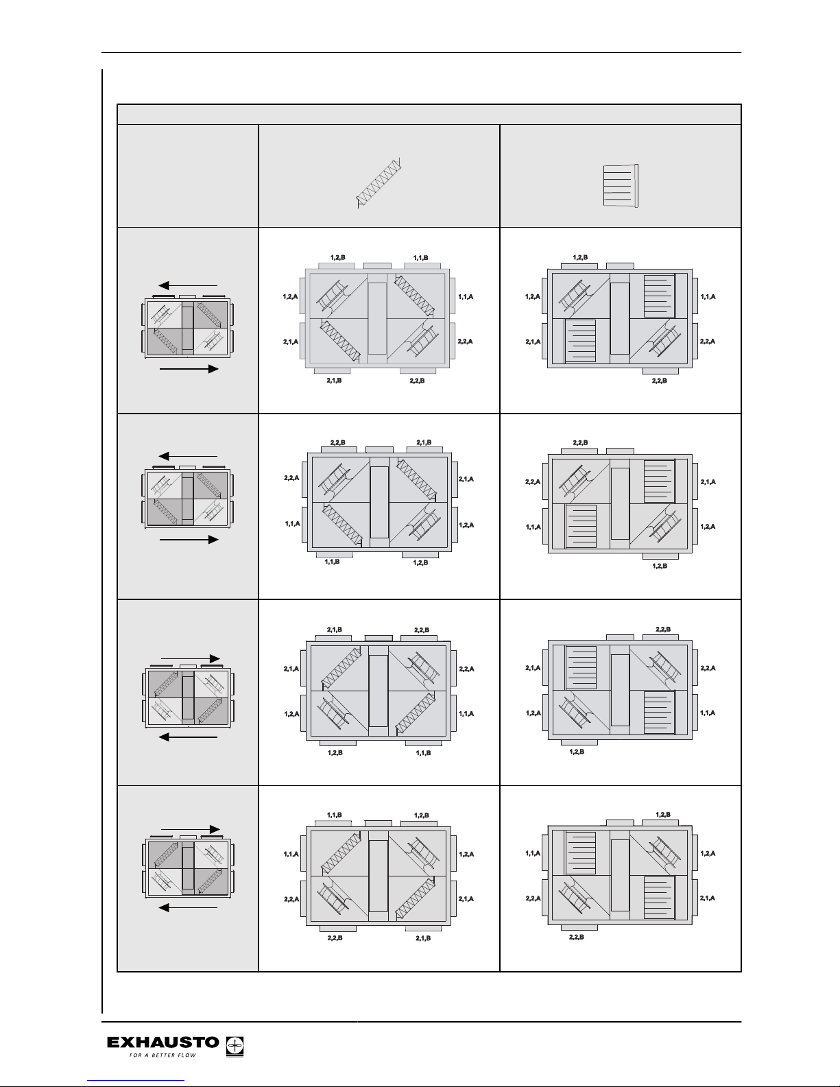
Optional spigot positioning in relation to fan placement and filter type
Fan placement and
airflows
Compact filters
RD12763-01
Bag filters
RD12762-01
Fan placement 1,
Right
RD12178-01
1
2
RD12979-01
RD12980-01
Fan placement 1, Left
RD12178-01
1
2
RD12981-01
RD12982-01
Fan placement 2,
Right
RD12179-01
2
1
RD12983-01
RD12984-01
Fan placement 2, Left
RD12179-01
2
1
RD12985-01
RD12986-01
3003434-2014-04-14
Product information
6/34
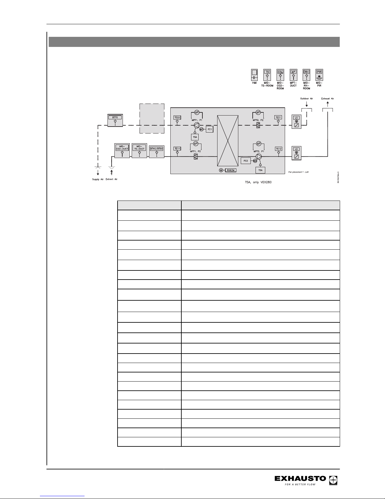
1.2 Terms used in these instructions
The simplified diagram shows a VEX unit with LEFT fan placement.
Component Function
BT40/BT50
1)
Fire thermostat, 40°C/50°C (extract air)
BT70
1)
Fire thermostat 70°C (supply air)
FC1 Frequency converter 1
FC2 Frequency converter 2
HMI
1)
Control panel
LS
1)
Closing damper, outdoor/exhaust air
M1 Fan motor, 1
M2 Fan motor, 2
MIO-CO2-DUCT
1)
CO2 sensor, duct
MIO-CO2-ROOM
1)
CO2 sensor, room
MIO-PIR
1)
PIR sensor
MIO-RH-ROOM
1)
Humidity sensor
MIO-TS-ROOM
1)
Temperature sensor, room
MIO-TS-DUCT
1)
Temperature sensor, extract air (external)
MPT1, P1 Airflow control, supply air
MPT1, P2 Filter monitor, extract air
MPT2, P1 Airflow control, extract air
MPT2, P2 Filter monitor, outdoor air
MPTDUCT Pressure transmitter, constant pressure regulation
RHX2M Control unit for the rotary heat exchanger
TE11 Temperature sensor, extract air
TE12 Temperature sensor, exhaust air
TE21 Temperature sensor, outdoor air
TE22 Temperature sensor, supply air
3003434-2014-04-14
Product information
7/34
Component Function
TSA Overheating
1)
Accessory. See checklist on the front page of these instructions.
1.3 Application
Comfort ventilation EXHAUSTO VEX is used for comfort ventilation tasks. Operating temperature range
for the unit – see section "Technical data".
Prohibited uses The VEX unit is not to be used to transport solid particles or in areas where there
is a risk of explosive gases.
1.4 Location requirements
Positioning The air handling unit is designed for indoor fitting. The air handling unit can be
ordered for outdoor installation (accessory Outdoor, OD).
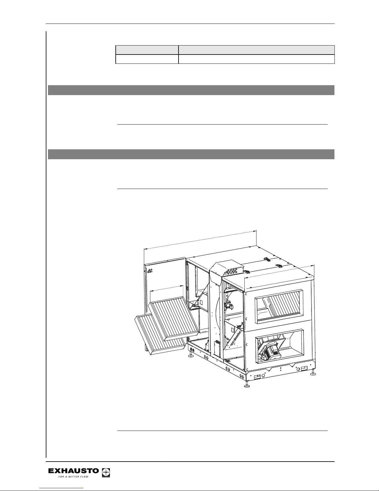
1.4.1 Spatial requirements
The drawing below indicates how much space is needed for servicing, replacing filters,
cleaning, etc.
A
1
2
1
0
1
9
2
5
RD11635-01
Compact filter: A = 575 mm
Bag filter: A = 592 mm
NB: A free height of at least 200 mm is required above the unit’s connection box.
3003434-2014-04-14
Product information
8/34
1.4.2 Requirements for underlying surface
When fitting the unit directly, the surface must be:
● flat
● level
● hard
● resistant to vibration
1.4.3 Requirements for duct system
Silencers The duct system must be fitted with silencers specified by the Project Manager,
which meet the requirements of the operating area.
Bends A duct bend may be fitted immediately after the unit, because the airflow in the
spigot has a uniformly moderate speed profile, which results in negligible system
pressure loss.
Insulation The duct system must be insulated against:
● condensation
● sound leakage
● heating/cooling losses
Condensation Condensation in the ducts may occur when the exhaust/outdoor air has high hu-
midity. EXHAUSTO recommends a condensation outlet is also fitted at the lowest
point in the ducts.
No duct connection If one or more of the spigots is not connected to a duct: Fit a
protective net to the spigots with a maximum mesh width of 20
mm.
3003434-2014-04-14
Product information
9/34
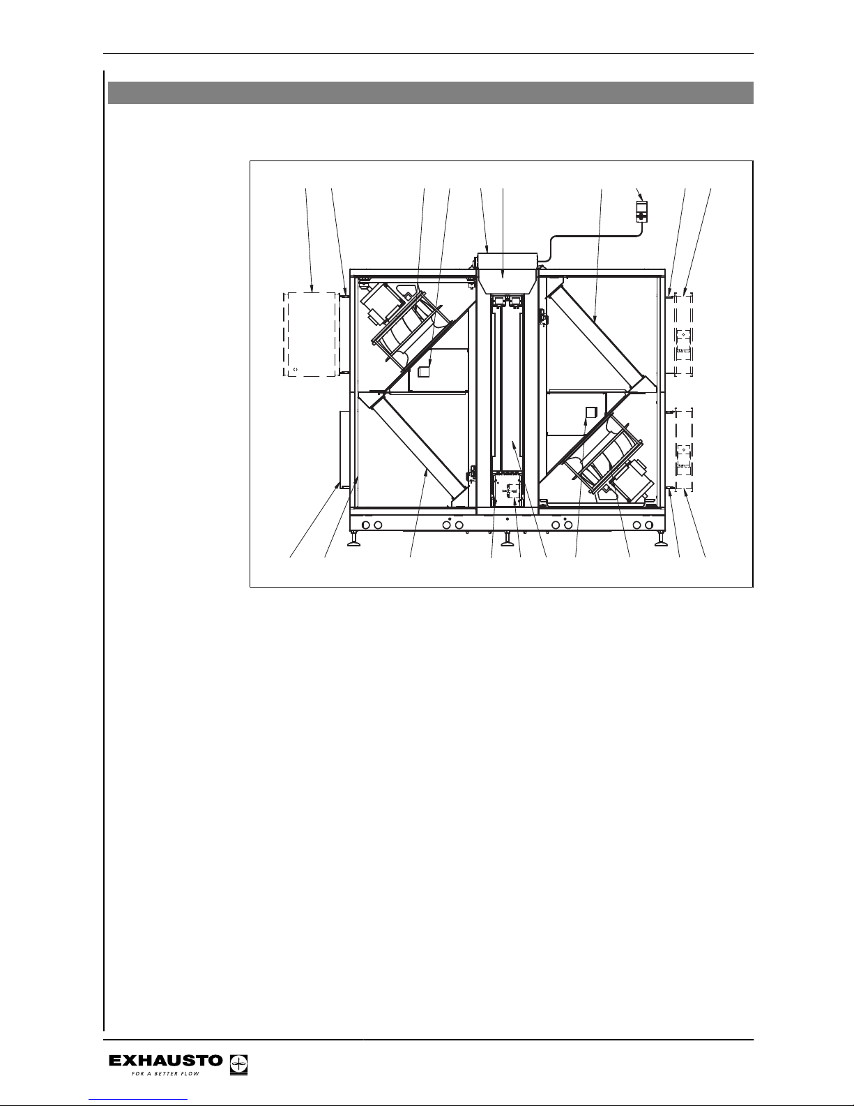
1.5 Description
1.5.1 The VEX unit design
VEX200L - V1 The drawing below illustrates the construction of the unit (without service doors).
2,1,A
1,2,A
1,1,A
2,2,A
2
35678
9
101112
13 14 1516 17 18 19
20
1
4
RD11702-01
3003434-2014-04-14
Product information
10/34
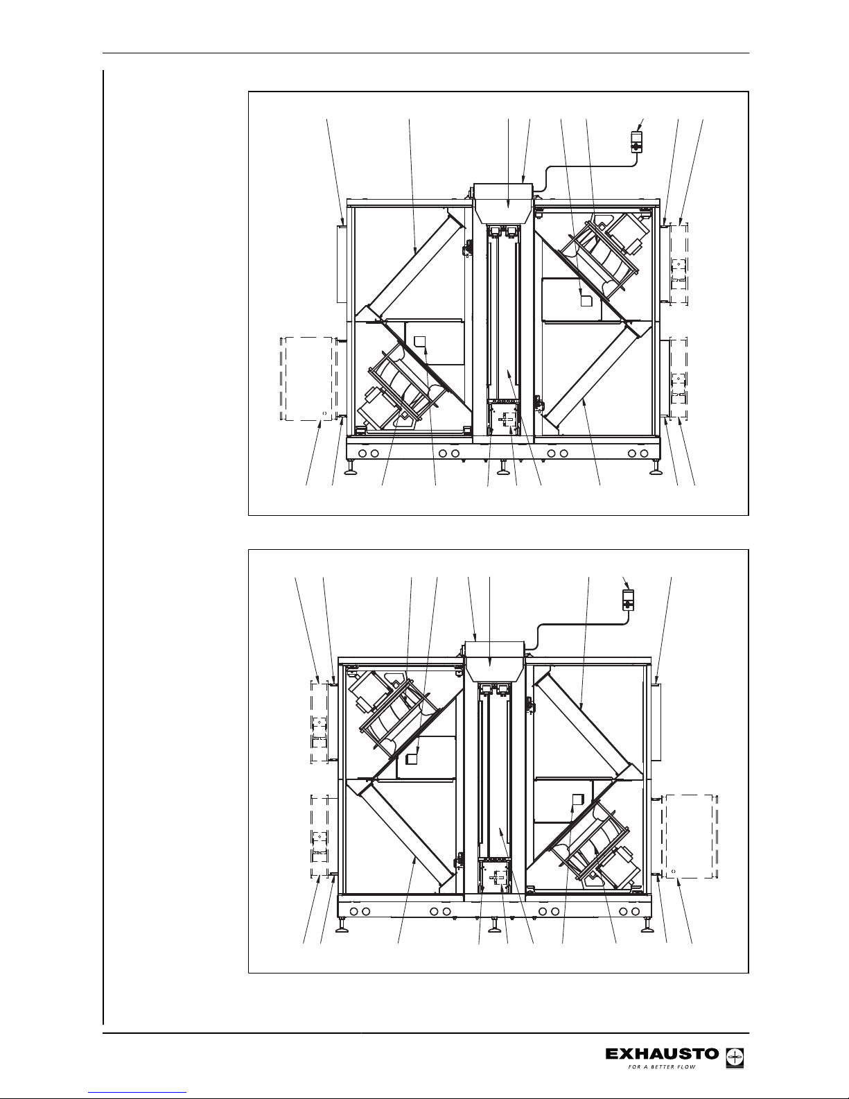
VEX200L - V2
7
2,1,A
1,2,A
1,1,A
2,2,A
13 16 17 8
9
20
3
4155618192012
14 1 2
RD11703-01
VEX200R - V1 The drawing below illustrates the construction of the unit (without service doors).
2,1,A
1,2,A
1,1,A
2,2,A
13161778
9
20
3
4
15
5
6 18 19 20 12
14
12
RD11704-01
3003434-2014-04-14
Product information
11/34
 Loading...