

Exhausto VEX200 series, EXact2 VEX240 series, EXact2 VEX250 series, EXact2 VEX260 series, EXact2 VEX270 series Basic Instructions
...Page 1
EXact Control System
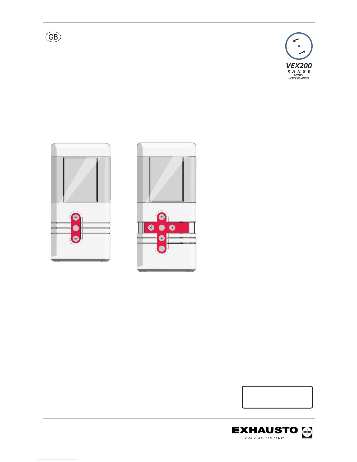
Basic instructions for the VEX200 series
EXHAUSTO
OK
EXHAUSTO
Esc
OK
Original instructions
3003246-2014-05-21
EXact_VEX200
EXHAUSTO A/S
Odensevej 76
DK-5550 Langeskov
Tel. +45 65 66 12 34
Fax +45 65 66 11 10
[email protected]
www.exhausto.dk
Page 2
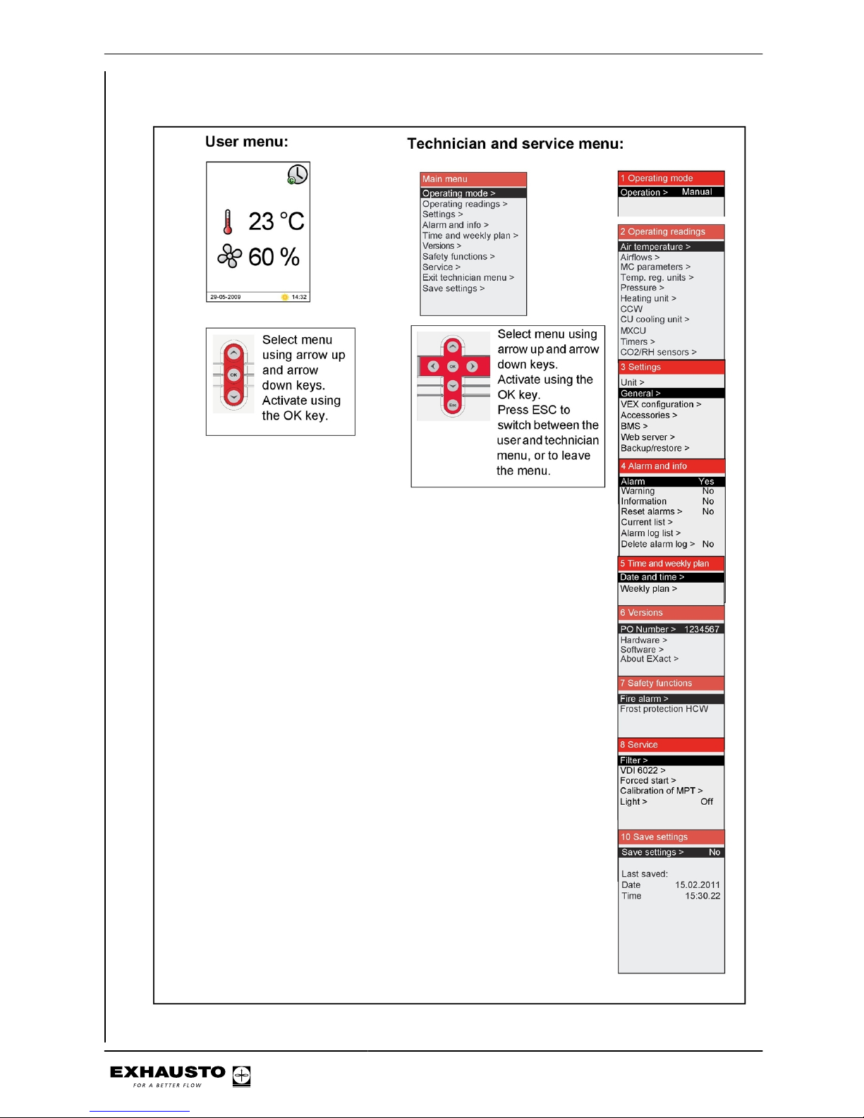
Menu structure
3003246-2014-05-21
2/100
Page 3

Symbols and software version
Symbols used in these instructions...........................................................................5
Software version...........................................................................................................5
Software version .......................................................................................................5
2. User mode
2.1. HMI panel................................................................................................................6
2.2. Display icons..........................................................................................................7
3. Operation, access codes and selecting language
3.1. Using the HMI panel..............................................................................................9
3.1.1. Using keys within the menus...........................................................................9
3.2. Access codes for technician and service menus.............................................10
3.3. IMPORTANT when servicing..............................................................................11
3.3.1. Auxiliary service panel...................................................................................12
Menu 3.2 - Selecting language..................................................................................13
Menu 3.2.1 - Setting date and time............................................................................13
Menu 3.2 - Reset settings...........................................................................................13
Menu 3.2 - Reload database.......................................................................................14
Menu 3.6 - Web server................................................................................................14
Menu 3.7 - Backup/restore.........................................................................................15
4. Starting unit operation
4.1. Getting started.....................................................................................................16
Start configuration....................................................................................................17
Menu 3.4 - Accessories...........................................................................................18
Menu 3.4 Connecting heating and cooling units .....................................................19
Menu 3.5 BMS.............................................................................................................20
Menu 3.5 - BMS.......................................................................................................20
4.3. What is an indoor air quality level?...................................................................20
Menu 1 - Selecting operating mode..........................................................................21
Menu 3.1.1 - Operating settings - Air regulation......................................................21
Menu 3.1.1 - Operating settings Balance................................................................23
Menu 3.1.1.5 Regulators ........................................................................................24
Menus 3.1.1.1.1 to 3.1.1.1.4 Configuring the selected indoor air quality levels....25
Menu 3.1.1.1.x - Air set point ..................................................................................25
Menu 3.1.1.1.x - Temperature set point ..................................................................25
Menu 3.1.1.1.x - Absolute / Relative temperature ..................................................25
Menu 3.1.1.1.x - Cooling relative start ....................................................................26
Menu 3.1.1.1.x - Heating relative start ....................................................................26
Menu 3.1.1.1.x - Cooling absolute start ..................................................................26
Menu 3.1.1.1.x - Heating absolute start ..................................................................27
Generally on temperature regulation ......................................................................27
Menu 3.1.8 - Temperature limits..............................................................................27
Menu 3.1.1.1.x - Supply air regulation, absolute ....................................................29
Menu 3.1.1.1.x - Room temperature regulation, absolute ......................................30
Menu 3.1.1.1.x - Supply air regulation, relative ......................................................31
Menu 3.1.1.1.x - Room temperature regulation, relative ........................................33
Menu 3.1.1 - Operation settings - Temperature regulation.....................................35
Compensation.............................................................................................................36
Menu 3.1.2 - Air compensation..................................................................................36
Menu 3.1.2.1 - CO2 compensation .........................................................................37
Menu 3.1.2.2 - Humidity compensation of airflow ...................................................38
Menu 3.1.2.3 - Airflow reduction .............................................................................38
Menu 3.1.2.4 - Outdoor compensation of airflow ....................................................39
Menu 3.1.3 - Temperature compensation.................................................................40
Outdoor air temperature compensation (menu 3.1.2.1) ..........................................40
Summertime compensation (menu 3.1.2.2) ............................................................41
Menu 3.1.4 + Menu 8.1 - Filter (monitoring in case of pressure) ............................41
Menu 3.1.4 + Menu 8.1 - Filter (monitoring with hour counter) ...............................42
Menu 3.1.5 - Night-time cooling ..............................................................................42
Menu 3.1.6 - Cold recovery.....................................................................................45
Menu 3.1.7 - Fan limits............................................................................................45
3003246-2014-05-21
3/100
Page 4
Menu 3.1.8 - Temperature limits for supply air and room........................................45
Room temperature limits..........................................................................................46
Menu 3.1.9 - Cooling/heat pump unit ......................................................................46
Menu 5 - Time and weekly plan.................................................................................47
Menu 5.1 - Date and time........................................................................................47
Menu 5.2 - Weekly plan ..........................................................................................48
Menu 7 - Safety functions..........................................................................................49
Menu 7.1 - Fire alarm..............................................................................................49
Menu 7.2 - Frost protection of HCW .......................................................................50
5. Operation
Menu 2 - Operating readings.....................................................................................52
Menu 2.1 - Air temperatures ...................................................................................52
Menu 2.1.1 - Set points for regulators ....................................................................53
Menu 2.2 - Airflows .................................................................................................53
Menu 2.3 - Motor controller parameters (MC parameters) .....................................53
Menu 2.4 - Temperature regulating units ................................................................54
Menu 2.5 - Pressure................................................................................................54
Menu 2.6 - Heating coil ...........................................................................................54
Menu 2.7 - Cooling/heat pump unit .........................................................................55
Menu 2.8 - CCW cold water coil .............................................................................55
Menu 2.9 - CU cooling unit......................................................................................55
Menu 2.10 - MXCU external cooling unit.................................................................55
Menu 2.11 - Hour counters......................................................................................56
Menu 2.12 - CO2/RH sensors (if mounted).............................................................56
Menu 6 - Versions.......................................................................................................56
Menu 8 - Service.........................................................................................................57
Auxiliary service panel.............................................................................................58
Menu 8.2 - VDI 6022................................................................................................59
Menu 8.3 - Forced start ..........................................................................................59
Menu 8.3.1 Fans......................................................................................................59
Menu 8.3.2 Recovery...............................................................................................59
Menu 8.3.3 Heating unit...........................................................................................60
Menu 8.3.4 Cooling unit...........................................................................................60
Menu 8.3.5 Dampers and relays..............................................................................60
Menu 8.4 - Calibrating MPT.....................................................................................60
6. Alarms
6.1. Alarms and info (Menu 4)....................................................................................62
6.2. Reset alarms........................................................................................................62
6.3. Alarm display – causes of errors.......................................................................62
6.4. List of alarms.......................................................................................................64
Appendix 1 - Simplified diagrams
Simplified diagrams....................................................................................................90
Simplified diagrams for unit with chiller ...................................................................90
VEX240-250-260-270L fan placement 1 ................................................................90
VEX240-250-260-270L fan placement 1 ................................................................90
VEX240-250-260-270L fan placement 2 ................................................................91
VEX240-250-260-270L fan placement 2 ................................................................91
VEX280L fan placement 1 ......................................................................................92
VEX280R fan placement 1 .....................................................................................93
VEX280L fan placement 2 ......................................................................................94
VEX280R fan placement 2 .....................................................................................95
Appendix 2 - Temperature resistance table
Temperature resistance table DC95..........................................................................96
3003246-2014-05-21
4/100
Page 5
Symbols and software version
Symbols used in these instructions
Prohibition symbol Failure to observe instructions marked with a prohibition symbol
may result in serious or fatal injury.
Danger symbol Failure to observe instructions marked with a danger symbol may
result in personal injury and/or damage to the unit.
Software version
Software version
These instructions are for use with the following version:
AHUC: 3.2.0.0
HMI: 3.2.0.0
3003246-2014-05-21
Symbols and software version
5/100
Page 6
2. User mode
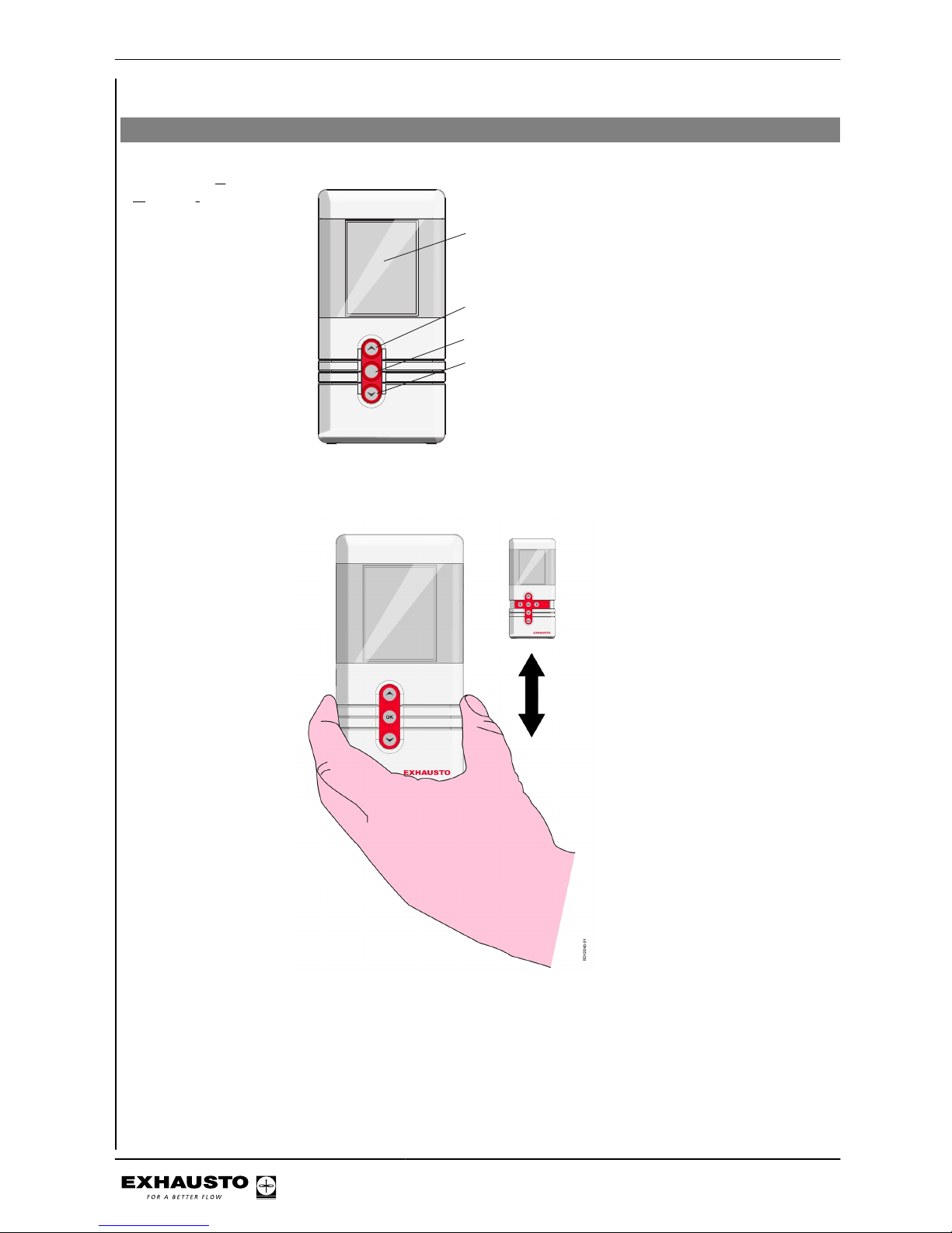
2.1 HMI panel
HMI panel - Human
Machine Interface
panel
mode
EXHAUSTO
OK
RD12248-01
Display
Browse menu or
set value
Activate menu/confirm key
Browse menu or
set value
If the front cover is extended, push it back in. The extra keys are for service technician use only.
3003246-2014-05-21
User mode
6/100
Page 7
2.2 Display icons
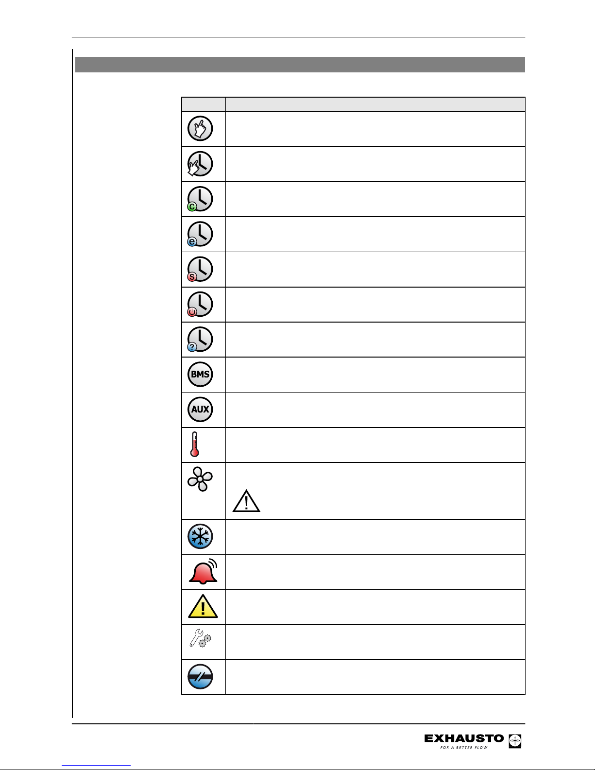
Icon Description
Manual operation
Timer overridden until next changeover in the timer schedule
Timer, current indoor air quality level is comfort
Timer, current indoor air quality level is economy
Timer, current indoor air quality level is standby
Timer, VEX has stopped
Timer, no changeover times defined in timer schedule
BMS-controlled operation
Externally-controlled operation
Set point for temperature shown in °C
Set point for ventilation shown as percentage: 0% = no ventilation OFF =
Unit is switched off - timer function cannot start up unit
BMS or Web server-controlled system overrides the OFF function. This means the system may start up even if set to OFF
The unit is running de-icing (De-ice)
Unit alarm. Contact the service technician who can help reset the alarm.
Icon is also shown in the technician menu
Warning. Contact the service technician who can help reset the warning.
Icon is also shown in the technician menu
Temporarily
in service
Service display connected
External start/stop disconnected. See Electrical Installation Guide for further information
3003246-2014-05-21
User mode
7/100
Page 8
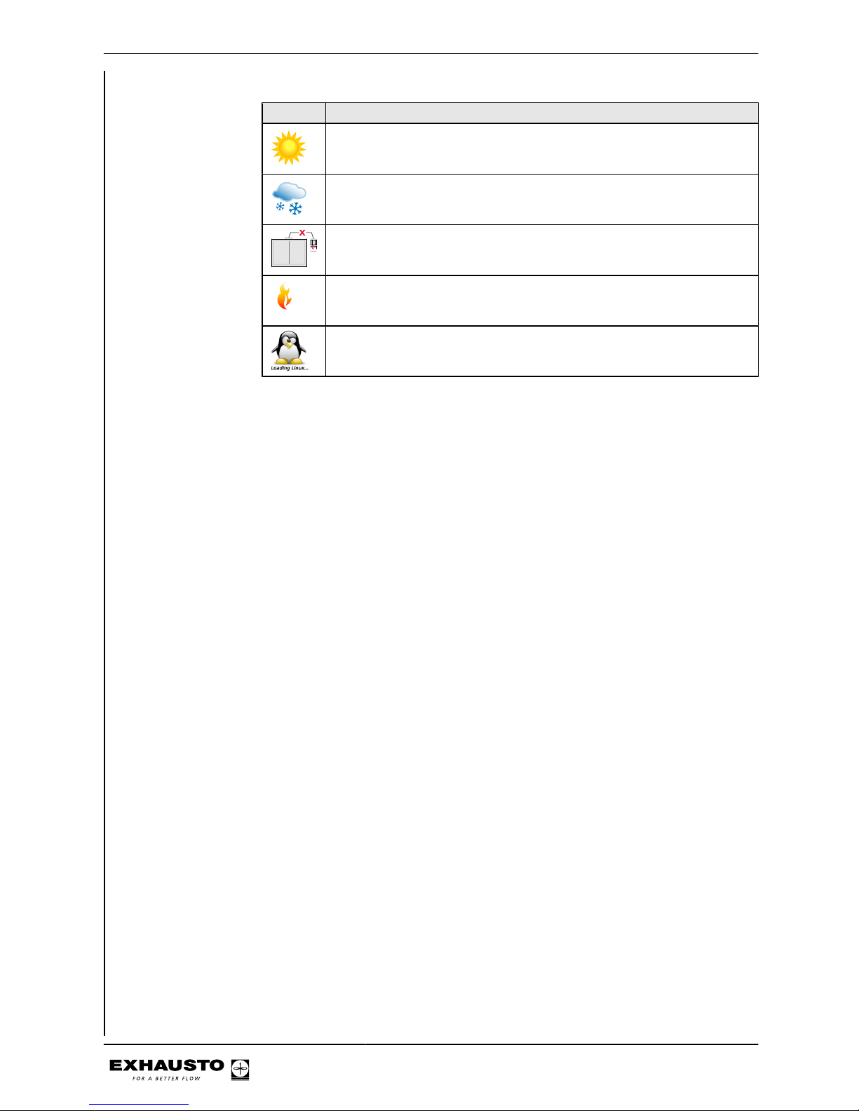
Icon Description
Summertime
Wintertime
No communication on the external BUS or communication between the
VEX and HMI is disconnected
Fire!
Fire alarm. Closed circuit open and the pre-set fire alarm function activated
Startup: Web server accessing database. The icon is displayed until the
HMI panel is ready for use.
3003246-2014-05-21
User mode
8/100
Page 9
3. Operation, access codes and selecting language
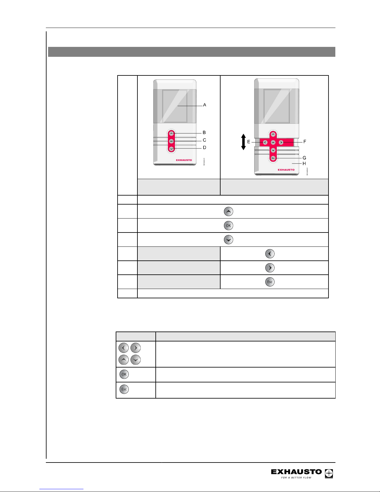
3.1 Using the HMI panel
Keys for user mode
or service mode
HMI panel ready for everyday use
HMI panel ready for service mode
A Display
B
key
C
key
D
key
E
key
F
key
G
key
H Service key cover
3.1.1 Using keys within the menus
Keys Used for...
Navigation and setting values
Confirm key - selecting menu
Change between daily user and technician mode
Exiting a menu without making changes
3003246-2014-05-21
Operation, access codes and selecting
language
9/100
Page 10
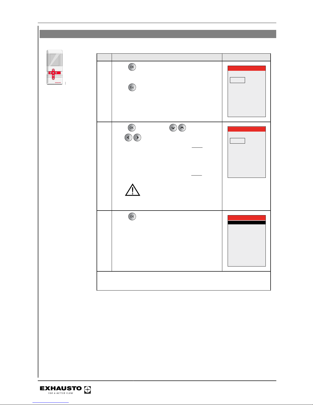
3.2 Access codes for technician and service menus
Step Action The display shows
1
Press for full display brightness (if the display
is in hibernation mode).
Press
Password
0000
2
Press and then press to set the value.
Use to shift to the next digit of the code.
● The code for technician mode is
1111 (some
menus are hidden or read-only). EXHAUSTO
recommends this mode is used for normal
service tasks
● The code for specialist mode is 3142 (full ac-
cess to all menus).
NB: incorrect settings (wrong val-
ues) may have a negative impact on unit
operation in some menus
Password
1111
3
Press to access main menu.
Main menu
Operating mode >
Operating readings >
Settings >
Alarm and info >
Time and weekly plan >
Versions >
Safety functions >
Service >
Exit technician menu >
Save settings >
Note
● Automatically logs out and returns to the user menu if no buttons are pressed
in a 30-minute period.
3003246-2014-05-21
Operation, access codes and selecting
language
10/100
Page 11
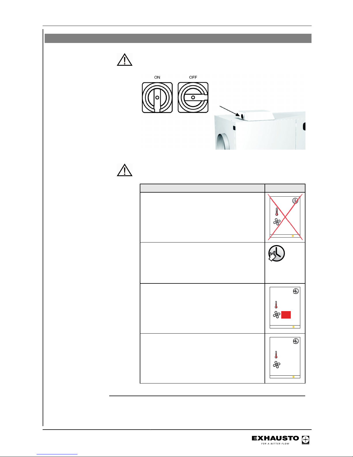
3.3 IMPORTANT when servicing
Do not open the service doors before the supply voltage has been disconnec-
ted at the isolation switch. The isolation switch is positioned on
the left side of the connection box on top of the unit.
Weekly plan It is important to set ventilation to OFF when the weekly plan is
active:
Set ventilation to OFF
NB - If the HMI panel shows 0% (VEX is inactive)
and the unit is operating to a weekly plan when
servicing begins, there is a risk that the program may change via a timer operation and restart the VEX unit.
21
0°C%
29-05-2009 14:32
● Log onto technician menu, using password 1111
● Change to manual operation via menu 1
● Change back to user menu
● The icon for manual operation appears in
the right-hand corner of the menu
● Press the OK button twice
● Use the arrow keys to adjust ventilation to
0%
23 °C
%
29-05-2013 14:32
0
● Press OK
● OFF will now appear on the display next to
the ventilation icon
23 °C
29-05-2013 14:32
OFF
3003246-2014-05-21
Operation, access codes and selecting
language
11/100
Page 12

BMS unit or Web
server
If BMS or Web server controls are used, they could override the
OFF function and the VEX may start up irregularly. To disconnect
the BMS or WEB server connection, you must remove the plug
from the connection board. Refer to the section on the terminal
board in the Electrical Installation Guide.
3.3.1 Auxiliary service panel
If the HMI panel is located far from the VEX, it is recommended that an auxiliary HMI
panel be connected to the VEX in the connection box.
RD12627-02
Auxiliary service panel which
overrides the fixed HMI panel
Fixed HMI-panel
Service panel connector - Exact
3003246-2014-05-21
Operation, access codes and selecting
language
12/100
Page 13
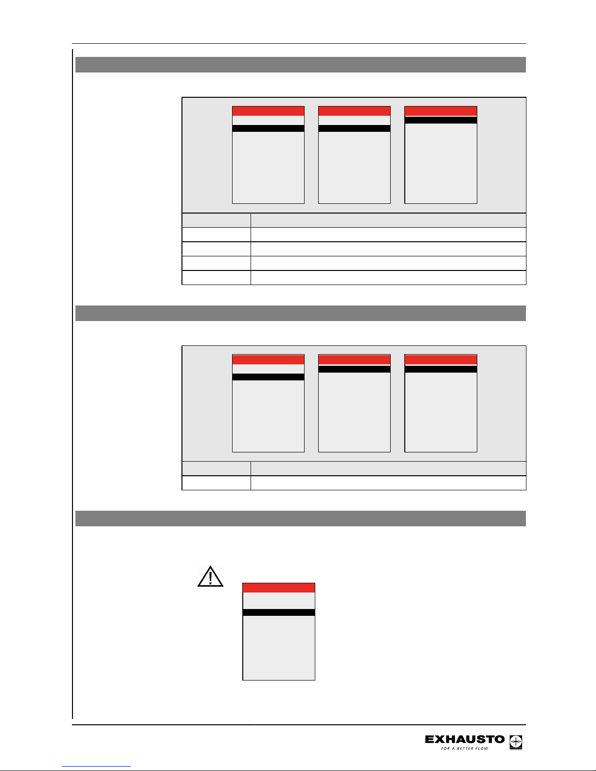
Menu 3.2 - Selecting language
Unit >
General >
VEX configuration >
Accessories >
BMS >
Web server >
Backup/restore >
3 Settings
3.2 General
Date and time >
Language >
Reset settings >
Reload database >
English
Main menu
Operating mode >
Operating readings >
Settings >
Alarm and info >
Time and weekly plan >
Versions >
Safety functions >
Service >
Exit technician menu >
Save settings >
Step Action
1 Select "Settings"
2 Select "General"
3 Select the required language in line 2 "Language"
4 Return to the main menu and select yes in "Save settings"
Menu 3.2.1 - Setting date and time
Unit >
General >
VEX configuration >
Accessories >
BMS >
Web server >
Backup/restore >
3 Settings
3.2 General
Date and time >
Language >
Reset settings >
Reload database >
English
3.2.1 Date and time
Date > 22-02-2009
Day >
Time >
Wednesday
13:11
Step Action
1 Select "Date and time" to set these parameters in Menu 3.2.1
Menu 3.2 - Reset settings
Selecting "Reset settings" resets the user settings. See the menu guide for details of
which menus are affected.
NB This cannot be reversed and the VEX will restart.
3.2 General
Date and time >
Language >
Reset settings >
Reload database >
English
3003246-2014-05-21
Operation, access codes and selecting
language
13/100
Page 14
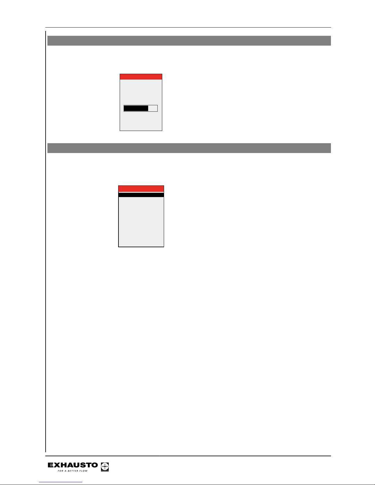
Menu 3.2 - Reload database
Selecting "Reset settings" resets the user settings. See the menu guide for details of
which menus are affected.
Database reloads
Initialising
Loading DB names
Menu 3.6 - Web server
Contact the network administrator for information on the correct IP address, etc. If the
admin password is lost, it can be reset to the factory setting. But note that this cannot
be reversed. See Exact Web server Instructions.
No
> 192.168.001.180
> 255.255.255.000
> 192.168.001.001
80
00:1F:79:00:00:D0
No
3.6 Web server
DHCP >
IP address
Subnet mask
Standard gateway
Port number >
MAC address
Reset password >
3003246-2014-05-21
Operation, access codes and selecting
language
14/100
Page 15

Menu 3.7 - Backup/restore
It is recommended that a backup copy of the VEX settings is made and saved on a
secure media. See the individual backup guidelines in the diagram:
+
Backup via the HMI panel
● Insert the USB plug in one of the web
server sockets
● Select menu Backup/restore
● It can take up to 20 seconds to establish
the connection to the USB
The backup file can only be saved on a USB
plug. Once the file has been saved it is not
possible to change the file name or type.
The file is named automatically as in this example: backup_20110918.file
Backup via web server
Follow the backup/restore instructions in the
web server guide. The backup file may be
saved on any medium (USB, PC etc.).
A backup file saved via the web server may
be renamed, but the file type cannot be
changed.
NB
If a backup file has been saved from the web
server and then renamed, it cannot be retrieved (restored) via HMI until the name has
been changed back to the standard form, see
"Via HMI panel".
If it is necessary to make backup files for several VEX, it is recommended that each file is
saved on a separate USB flash drive or that
a folder is created for each VEX on which the
backup files can be saved.
3003246-2014-05-21
Operation, access codes and selecting
language
15/100
Page 16
4. Starting unit operation
The Modbus connectors must not be connected or removed while the
units are powered up. Both Modbus units must be switched off before
making changes, otherwise the units may be damaged.
During commissioning, it may be necessary to work with the control
system boxes open. Components in these boxes must only be touched
with electrically-insulated tools.
Before doing any work on motor controls or motor cables and terminal
boxes, the power supply must be switched off for at least five minutes
to allow the capacitors to discharge.
Before commissioning begins
● Check that the supply voltage is connected
● Set the HMI panel to specialist mode. See section 2.2
4.1 Getting started
From the main menu, follow the steps below to start the commissioning process.
Commissioning
Step Action Menu
1 Configure any external accessories or units (heating or
cooling coils (CCW, MXCU), chiller, sensors, etc.)
3.4
2 Select operating mode - Manual operation is the recom-
mended setting during commissioning
1
3 Set/activate operation settings 3.1
4 Program weekly plan 5.2
5 Set safety function settings 7
6 Select operating mode - change to timer operation if re-
quired
1
The various menu items are explained later in this section.
REMEMBER - Save
settings
After changing menu settings it is always important to return to the main menu to
save your settings by selecting "Save settings" in menu 10 (select yes). If power is
disrupted before the settings are saved, the changes must be re-entered.
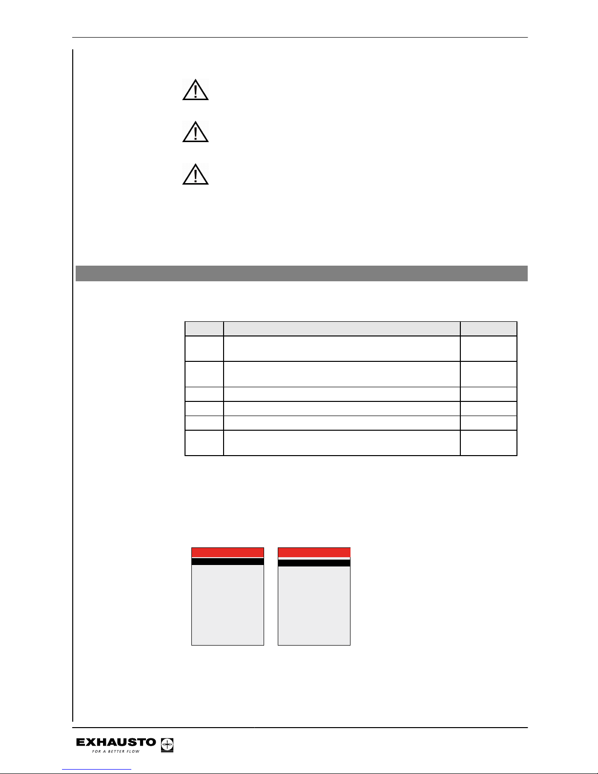
Main menu
Operating mode >
Operating readings >
Settings >
Alarm and info >
Time and weekly plan >
Versions >
Safety functions >
Service >
Exit technician menu >
Save settings >
10 Save settings
Save settings >
Last saved:
Date
Time
No
15.02.2011
15:30.22
3003246-2014-05-21
Starting unit operation
16/100
Page 17
Start configuration
Step Action
1 Check that the correct configuration for the VEX has been selected
at the factory via menu 3.3.
2 Check that all accessories have been configured in menu 3.4
3 If a CO2sensor is installed, check in Menu 3.1.2.1 "CO2compensa-
tion" whether CO2compensation has been activated.
4 If the humidity sensor (RH sensor) has been installed, check that
humidity compensation has been activated in Menu 3.1.2.2 Humidity
compensation.
5 Go to Menu 4.5. Current list, and check whether any units from the
configuration menu are reporting errors. Alarm icon is shown in the
menu bar
6 If a unit is reporting an error but has been correctly configured, check
the installation
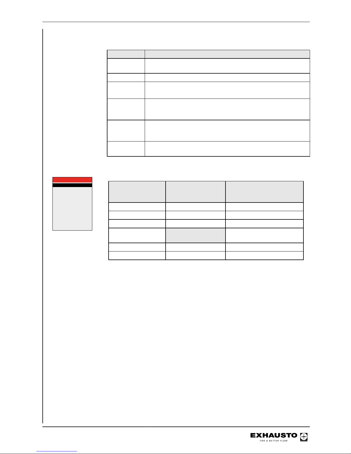
3.3 VEX configuration
VEX-type >
VEX-size >
Fan positioning >
Direction >
Rotor type >
Cleaning zone >
Heating coil >
Cooling unit >
200
1
Right
Cond.
None
HCE
Power step HCE >
TS >
BMS >
1
TS Room
None
x40
CCW
PIR > Active
Line in Menu 3.3 Factory-set and
should not be
changed.
Comments
VEX type x
VEX size x
Fan placement x
Direction Adjustable. See section select-
ing Left/Right
Rotor type x
Cleaning zone x
3003246-2014-05-21
Starting unit operation
17/100
Page 18
Menu 3.4 - Accessories
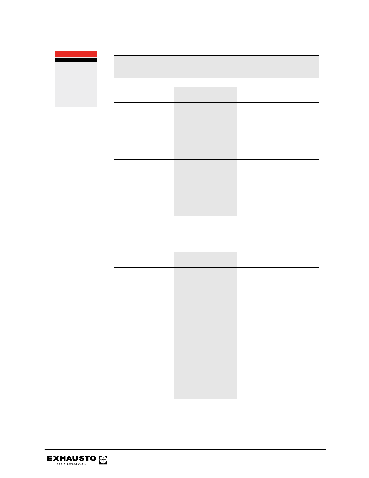
Ice-detect. >
De-icing method >
Heating coil >
Cooling unit >
Power step HCE >
Filter detect. >
PIR >
TS >
CO2 >
RH >
Dining solution
3.4 Accessories
Pressure
0
MHCE
None
4
Timer
PIR1
TS Room
MIOCO2
None
No
Line in Menu 3.4 Factory-set and
should not be
changed.
Comments
Ice detection method x ● None
De-icing method De-icing not available
● 0
Heating unit Options:
● IHCW (cannot be used for
VEX200)
● MHCE (Electric heating
coil)
● MHCW (Water heating
coil),
● None
Cooling unit Options:
● CH
● MXCU (external cooling
unit)
● CCW (cold water coil)
● CU (EXHAUSTO cooling
unit)
● None
Filter detection x Should only be changed when
sensors for detecting filter soiling are retrofitted. Options:
● Pressure
● Timer
Power step HCE This menu item is only active if
MHCE is selected
PIR Activating PIR sensor. Op-
tions:
● Both (Both MIOPIR and
PIRB connected)
● PIR2 (PIRB connected)
● PIR1 (MIOPIR connected)
● None
When the sensor(s) is/are activated by movement in the
room, the VEX will be overridden and set to comfort level.
Comfort level will be maintained for the time set on the
rear of the sensor (PIRB), after
which the VEX will return to the
previous indoor climate level.
NB: The time interval for MIOPIR is a fixed 10 minutes and
cannot be changed).
3003246-2014-05-21
Starting unit operation
18/100
Page 19
Line in Menu 3.4 Factory-set and
should not be
changed.
Comments
TS Activation of external tempera-
ture sensor and selection of
type. Options:
● TS DUCT
● TS ROOM
● None
CO2 Activation of CO2 sensor Op-
tions:
● None
● MIOCO2
● CO2B (sensor connected
to AI SPARE)
● BMS
RH Activation of RH sensor. Op-
tions:
● BMS
● RHB (sensor connected to
AI SPARE)
● MIORH
● None
Dining solution
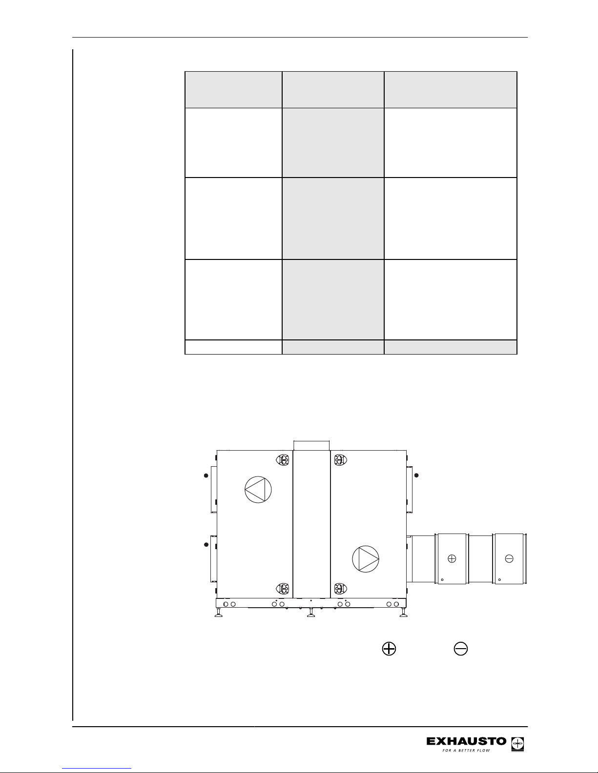
Menu 3.4 Connecting heating and cooling units
Location A heating coil and a cooling unit can be connected to the VEX. The example below
(VEX200) shows the position of the coils in relation to the VEX unit.
RD12313-02
Heating coil - Cooling unit
3003246-2014-05-21
Starting unit operation
19/100
Page 20
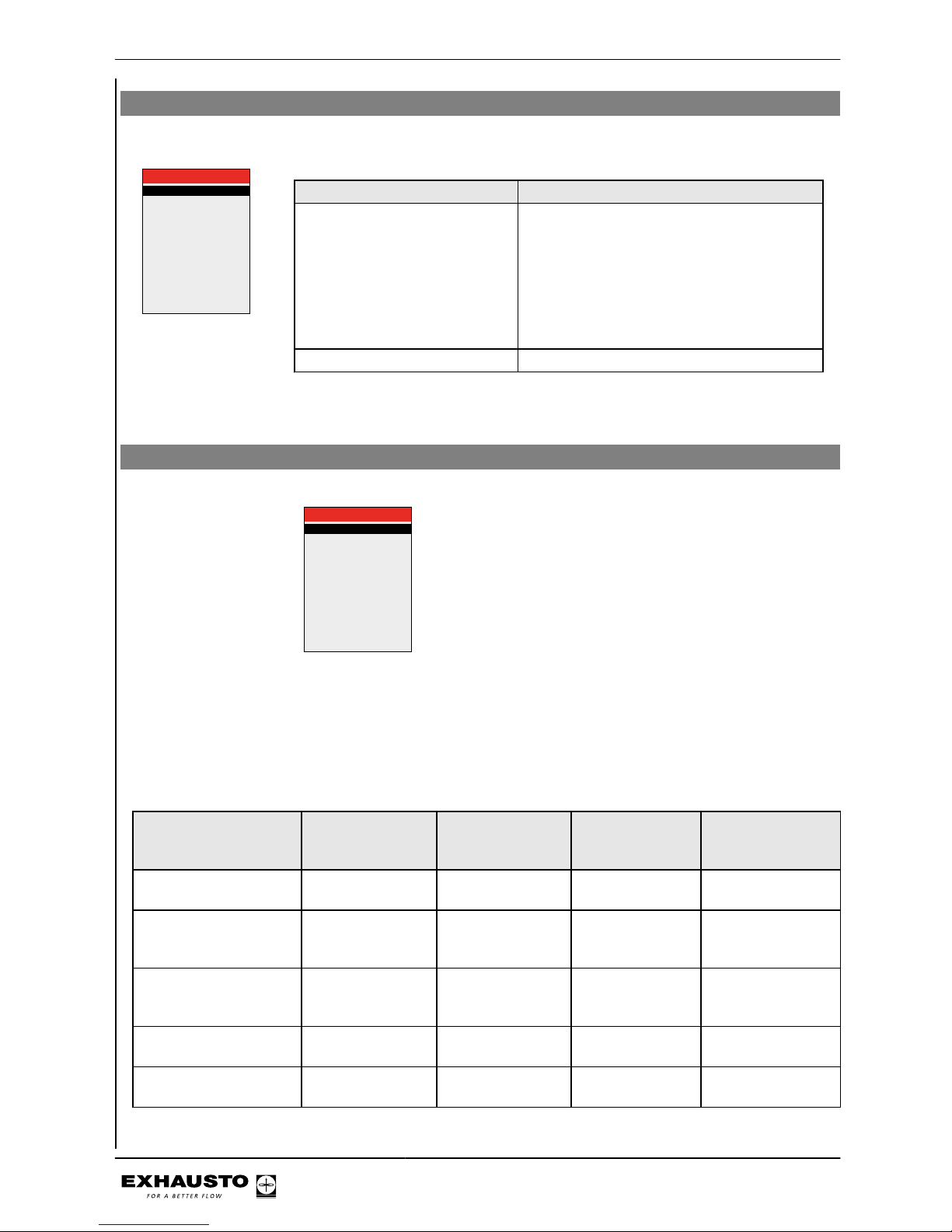
Menu 3.5 BMS
Menu 3.5 - BMS
BMS >
Configuration >
3.5 BMS
None
Line in Menu 3.5 Comments
BMS Activating override control system BMS Op-
tions:
● None
● LON
● Modbus
● MTCP
● BACnet MSTP
● BACnetIP
Configuration Configuration of Modbus and BACnet MSTP.
BMS configuration See detailed description in the instructions for the protocols.
4.3 What is an indoor air quality level?
Example
3.1.1.1.1 Comfort
Air setpoint >
Air setpoint,cool >
Temp. setpoint >
Abs. /Rel. >
Cool rel. start >
Cool abs. start >
Heat rel. start >
Heat abs. start >
60
80
21,0
Relativ
1,0
---
-1,0
---
%
%
°c
K
K
Indoor air quality
level definition
The four indoor air quality levels - Comfort, Standby, Economy and Manual - are
defined in menus 3.1.1.1.1 to 3.1.1.1.4. Parameters such as ventilation and temperature set points and control method for a given indoor air quality level are grouped in a menu, as shown in the example above. The table below shows suggested
settings for each mode:
Indoor climate levels Energy saving People in the
room
Air replacement* Deviation from de-
sired room temperature*
(Ventilation stopped) - No No ventilation No control of room
temperature
Economy Menu
3.1.1.1.3
Large No Low Greatest tempera-
ture deviation permitted*)
Standby Menu 3.1.1.1.2 Small No Low Least temperature
deviation permitted*
Comfort Menu 3.1.1.1.1 None Yes High Precise tempera-
ture
Manual Menu 3.1.1.1.4 Dependent on set-
ting
Yes/No Adjustable Adjustable
3003246-2014-05-21
Starting unit operation
20/100
Page 21

* Air replacement and temperature deviation set via the HMI panel.
The current indoor air quality level can be controlled in five ways:
● Via a weekly plan, based on the given operating requirements. Set via HMI panel.
● via an HMI panel in the room.
● via sensor(s) placed in the room or in the extract air duct (e.g. MIO-PIR, MIO-CO2,
MIO-RH, MIO-TS)
● via a PC connected to the integral web server
● via a high-level control system (e.g. BMS unit)
NB The Comfort indoor air quality level is the overriding level. The comfort level
is also activated if a mounted PIR sensor gives a signal (the unit changes from
an energy-saving indoor climate level/OFF).
Menu 1 - Selecting operating mode
1 Operating mode
Operation >
Manual
Select If
Manual The unit is intended to always operate at the same indoor air quality
level (set in Menu 3.1.1.1.4) and operation is controlled manually via
the HMI panel or the Web server
Timer The unit is controlled automatically via a fixed weekly plan
Note during commissioning
EXHAUSTO recommends that the operating mode be set to Manual during commissioning and changed to Timer operation when complete.
NB: for manual When the unit is operating in Manual air quality level, the temperature set point
(Temp. set point) and Air set point values are shown immediately in the user menu.
3.1.1.1.4 Manual
Air setpoint >
Air setpoint,cool >
Temp. setpoint >
Abs. / Rel. >
Cool rel. start >
Cool abs. start >
Heat rel. start >
Heat abs. start >
60
80
21,0
Relativ
1,0
---
-1,0
---
%
%
°c
K
K
2160°C
%
29-05-2009 14:32
Menu 3.1.1 - Operating settings - Air regulation
3.1.1 Operating settings
IAQ. levels >
Air reg. >
Temp. reg. >
Balance >
Regulators >
Supply air
1
1,0
The control method can be selected from the methods shown in the table. Note that
some of these methods require that an optional pressure sensor is fitted in one or
more ducts (MPTDUCT).
3003246-2014-05-21
Starting unit operation
21/100
Page 22
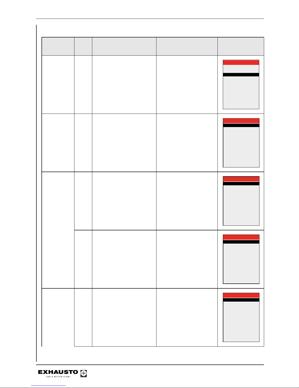
Method Meth-
od no.
(1-8)
Description Following parameters are
set
Menu
Manual control
1 Constant speed
Manual control of fan speed
● Balance
3.1.1 Operating settings
IAQ. levels >
Air reg. >
Temp. reg. >
Balance >
Regulators >
Supply air
1
1,0
Airflow control
2 Constant airflow
Maintains the airflow, compensating for changes in the
ducting system, filter soiling,
etc.
● Extract airflow values
for maximum and minimum ventilation (see
capacity diagram in
VEX instructions)
● Supply air balance relative to extract air
3.1.1.4 Constant airflow
Setp. maks. >
Setp. min. >
Balance > 1,00
10000l/s
0l/s
Constant
pressure regulation of extract air
3 Constant pressure-regulated
extract air with fixed supply air
setting
Requirements:
● MPT-DUCT negative
pressure sensor in the
extract air duct. Available
as an accessory
● Extract airflow values
for maximum and minimum ventilation
● Fixed setting for supply
airflow
3.1.1.4 Constant pressure
Extract air:
Setp. max. >
Setp. min. >
Setp. >
Supply air:
1000Pa
0Pa
0l/s
5 Constant pressure-regulated
extract air with slave-controlled supply air
Requirements:
● MPT-DUCT negative
pressure sensor in the
extract air duct. Available
as an accessory
● Extract airflow values
for maximum and minimum ventilation
● Supply air balance relative to extract air
3.1.1.4 Constant pressure
Extract air:
Setp. max. >
Setp. min. >
Balance >
Supply air:
1000Pa
0Pa
1.00
Constant
pressure regulation of supply air
4 Constant pressure-regulated
supply air with fixed extract air
setting
Requirements:
● MPT-DUCT overpressure sensor in the supply
air duct. Available as an
accessory
● Supply airflow values
for maximum and minimum ventilation
● Fixed setting for extract
airflow
3.1.1.4 Constant pressure
Supply air:
Setp. max. >
Setp. min. >
Setp. >
Extract air:
1000Pa
0Pa
0l/s
3003246-2014-05-21
Starting unit operation
22/100
Page 23
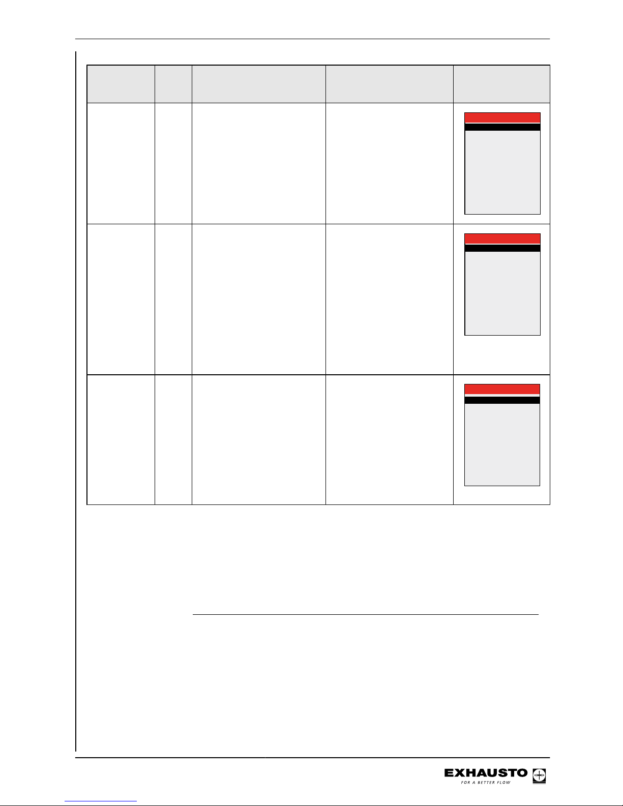
Method Meth-
od no.
(1-8)
Description Following parameters are
set
Menu
6 Constant pressure regulated
supply air with slave-controlled extract air
Requirements:
● MPT-DUCT overpressure sensor in the supply
air duct. Available as an
accessory
● Supply airflow values
for maximum and minimum ventilation
● Extract air balance relative to supply air
3.1.1.4 Constant pressure
Supply air:
Setp. max. >
Setp. min. >
Balance >
Extract air:
1000Pa
0Pa
1.00
Constant
pressure regulation of both
extract air and
supply air
7 Constant pressure regulation
of both extract air and supply
air
Requirements:
● MPT-DUCT negative
pressure sensor in the
extract air duct. Available
as an accessory
● MPT-DUCT overpressure sensor in the supply
air duct. Available as an
accessory
● Extract airflow values
for maximum and minimum ventilation
● Supply airflow values
for maximum and minimum ventilation
3.1.1.4 Constant pressure
Extract air:
Setp. max. >
Setp. min. >
Setp. max. >
Setp. min. >
Supply air:
1000Pa
0Pa
1000Pa
0Pa
External control of fan
speeds
8 External control of both ex-
tract air and supply air
Requirements:
● Two MIO modules to convert 0–10 V to Modbus
● FC max/FC min: Control signal range for external control (e.g. 2-10
V signal)
● Control signal to override external damper* in
the event of, e.g. nighttime cooling or fire
*or other third-party accessory, which is controlled by
external control
3.1.1.4 AUX
Type >
BFO
BMS
101None
Menu 3.1.1 - Operating settings Balance
Definition Balance is the required ratio between the supply and extract airflows. The balance
can only be maintained within certain operating ranges, limited by factors such as:
● Duct characteristics
● Minimum fan rpm
● Minimum airflow required
● Maximum airflow required
3003246-2014-05-21
Starting unit operation
23/100
Page 24

Example of balance The examples show a unit with manual fan control and balances of 0.80 and 1.20
respectively.
Range The required airflow is
A outside the unit’s normal operating range
B balanced
C unbalanced
NB Less than 1 = less supply air - Greater than 1 = less extract air
Note for methods 3,
4, 7 and 8
Balance is not active for air regulation methods 3, 4, 7 and 8.
Menu 3.1.1.5 Regulators
3.1.1.5 Regulators
Room temperature >
Supply air temp. >
Supply airflow >
Extract airflow >
Supply pressure >
Extract pressure >
Heat retention >
3003246-2014-05-21
Starting unit operation
24/100
Page 25
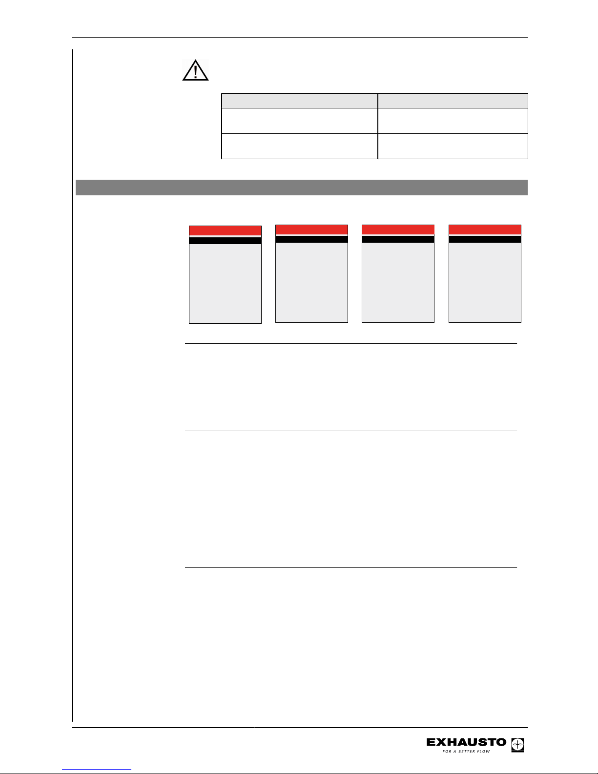
Kp and Ti settings should only be changed by persons trained in commissioning ventilation systems.
If the following is selected Permitted operations
Technician mode (code 1111) Read the settings for the various
regulators
Specialist mode (code 3142) Set Kp and Ti for the various reg-
ulators
Menus 3.1.1.1.1 to 3.1.1.1.4 Configuring the selected indoor air quality levels
The menus for the four indoor air quality levels contain the same menu items:
3.1.1.1.1 Comfort
Air setpoint >
Air setpoint,cool >
Temp. setpoint >
Abs. /Rel. >
Cool rel. start >
Cool abs. start >
Heat rel. start >
Heat abs. start >
60
80
21,0
Relativ
1,0
---
-1,0
---
%
%
°c
K
K
3.1.1.1.2 Standby
Air setpoint >
Air setpoint,cool >
Temp. setpoint >
Abs. /Rel. >
Cool rel. start >
Cool abs. start >
Heat rel. start >
Heat abs. start >
60
80
21,0
Relativ
1,0
---
-1,0
---
%
%
°c
K
K
3.1.1.1.3 Economy
Air setpoint >
Air setpoint,cool >
Temp. setpoint >
Abs. / Rel. >
Cool rel. start >
Cool abs. start >
Heat rel. start >
Heat abs. start >
60
80
21,0
Relativ
1,0
---
-1,0
---
%
%
°c
K
K
3.1.1.1.4 Manual
Air setpoint >
Air setpoint,cool >
Temp. setpoint >
Abs. / Rel. >
Cool rel. start >
Cool abs. start >
Heat rel. start >
Heat abs. start >
60
80
21,0
Relativ
1,0
---
-1,0
---
%
%
°c
K
K
Menu 3.1.1.1.x - Air set point
Definition Used to set the desired ventilation level for the given indoor air quality level, from 0
to 100%. Press "OK" to end.
Menu 3.1.7 - limits
menu
See the range limits for fan output in Menu 3.1.7 in the HMI panel.
Menu 3.1.1.1.x - Temperature set point
Definition The required supply air or room temperature is set here. If "Absolute" indoor air
quality level is selected (see next section), then the temperature set point can be
selected (with 0.5 degree difference) within the configured "Cooling absolute start"
and "Heating absolute start" ranges (for more details see relevant section).
Menu 3.1.8 - limits
menu
See the range limits for supply air temperature and room temperature in Menu 3.1.8
in the HMI panel.
Menu 3.1.1.1.x - Absolute / Relative temperature
Definition Used to select supply air or room temperature in relation to either absolute or relative
temperature.
Absolute - Specify start temperature for heating coil or cooling unit.
Relative - Permitted temperature changes relative to the heating coil or cooling unit
start temperature. See how the temperature variation follows when the set point is
altered (diagram below, dotted lines).
3003246-2014-05-21
Starting unit operation
25/100
Page 26
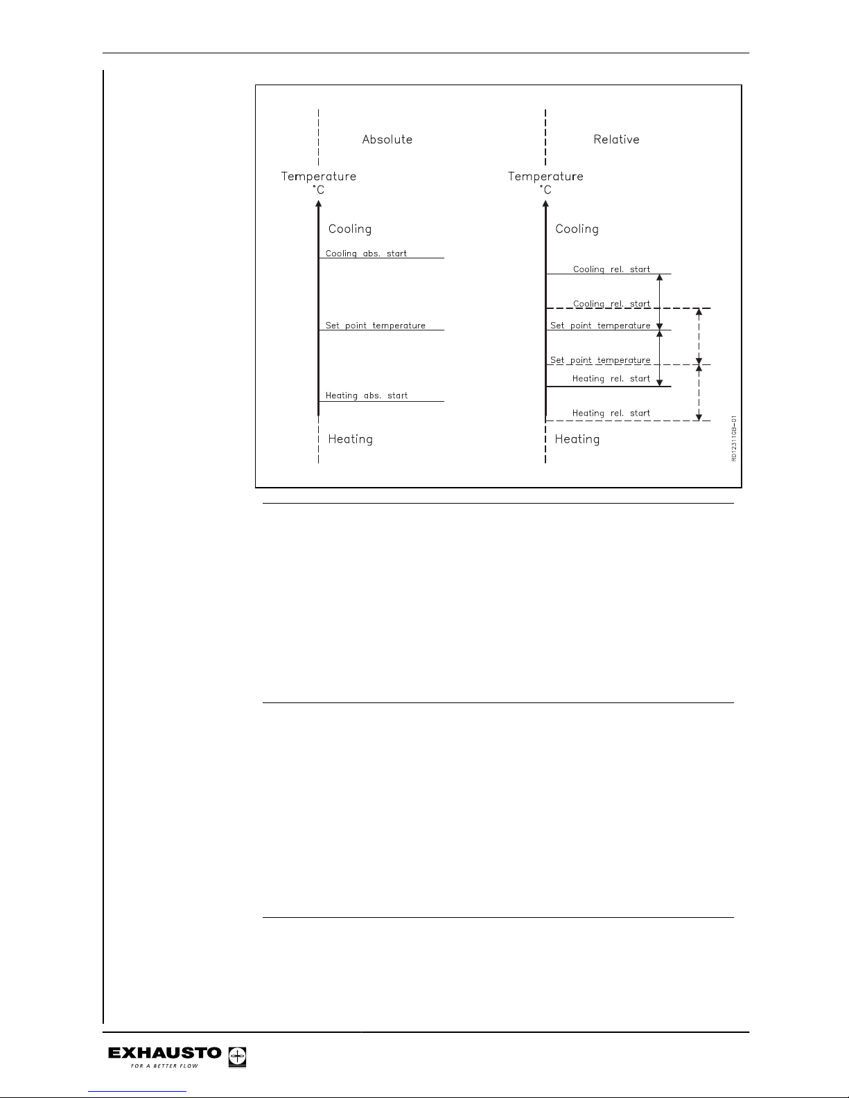
Menu 3.1.1.1.x - Cooling relative start
Definition This value determines when cooling must start in relation to the relative tempera-
ture. Low value = narrow temperature regulation range, leading to a comfortable
indoor climate. High value = wider temperature regulation range, which provides
cooling energy savings. Lower and upper limits are shown in the display.
Example If the required room temperature is 21°C, and Cooling Rel. start in the indoor air
quality level menu is set to 3K, the cooling unit will begin to operate on a warm day
when the temperature exceeds 21°C + 3K = 24°C.
Menu 3.1.1.1.x - Heating relative start
Definition This value determines when the heating coil must start in relation to the relative
temperature. Low value = narrow temperature regulation range, leading to a comfortable indoor climate. High value = wider temperature regulation range, which
saves energy because of lower heating requirements. Lower and upper limits are
shown in the display.
Example If the required room temperature is 21°C, and Heating Rel. start in the indoor air
quality level menu is set to -3K, the heating coil will begin to operate on a cold day
when the temperature falls below 18°C (21°C - 3K).
Menu 3.1.1.1.x - Cooling absolute start
Definition This value determines when cooling must start in relation to the absolute tempera-
ture. Lower and upper limits are shown in the display.
3003246-2014-05-21
Starting unit operation
26/100
Page 27
Example If Cooling abs. start is set to 24°C, the cooling unit will first start to operate when
the temperature exceeds 24°C, even though the daily user has set the required
room temperature to 21°C.
Menu 3.1.1.1.x - Heating absolute start
Definition This value determines when heating must start in relation to the absolute temper-
ature. Lower and upper limits are shown in the display.
Example If Heating abs. start is set to 18°C, the heating coil will not start to operate until the
temperature falls below 18°C, even though the daily user has set the required room
temperature to 21°C.
Generally on temperature regulation
● Start by setting the max. and min. limits
● Set the temperature setpoint
● For other regulators, first set the max./min. and then the setpoint
3.1.1 Operating settings
IAQ. levels >
Air reg. >
Temp. reg. >
Balance >
Regulators >
Supply air
1
1,0
If temperature regulation is changed from Supply Air to Room, the functions on the
next pages will be enabled, and invalid values will be adjusted to valid values. If
temperature regulation is changed from Room to Supply Air, nothing will happen,
as the limits for Room are always within the limits for Supply Air.
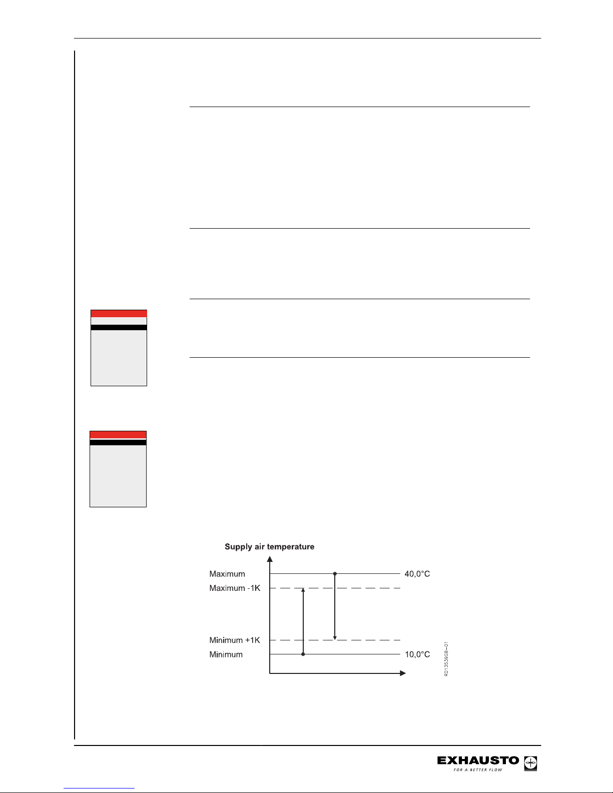
Menu 3.1.8 - Temperature limits
Grænser tillufttemp.
Minimum >
Maksimum >
Grænser rumtemp.
Minimum >
Maksimum >
Maksimum ∆T >
10.0
35.0
10.0
35.0
10.0
°C
°C
°C
°C
K
3.1.8 Temperaturgrænser
Limits, supply air
temperature
3003246-2014-05-21
Starting unit operation
27/100
Page 28
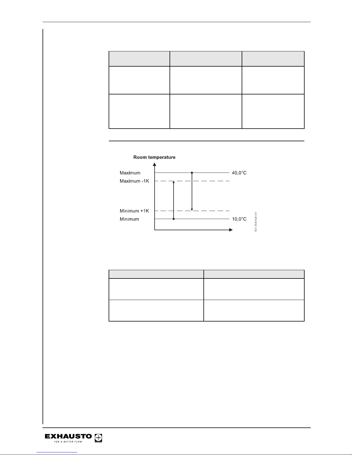
NB Max. and Min. may never be set closer to each other than 1K.
If the following is selected
temperature will be controlled by...
NB
supply air regulation supply air temperature Supply air temperature
will never be higher than
"Maximum" or lower
than "Minimum".
room temperature regulation
extract air temperature or
TSROOM
However, supply air
temperature will never
be higher than "Maximum" or lower than
"Minimum".
Limits, room temperature
NB Max. and Min. may never be set closer to each other than 1K.
If the following will be adjusted....
Supply air temp. maximum is set lower
than the room temp. maximum.
The room temp. maximum is automatically reduced to the same value as the
supply air temp. maximum.
The supply air temp. minimum is set
higher than the room temp. minimum.
The room temp. minimum is automatically increased to the same value as the
supply air temp. minimum.
3003246-2014-05-21
Starting unit operation
28/100
Page 29
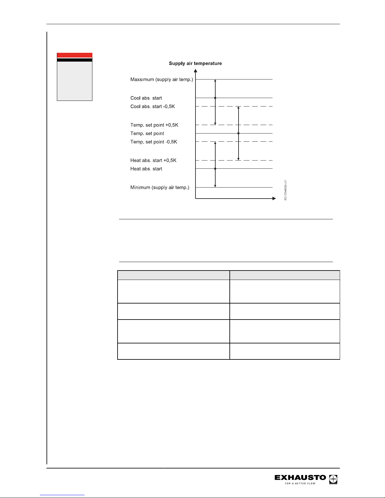
Menu 3.1.1.1.x - Supply air regulation, absolute
Air setpoint >
Air setpoint,cool
Temp. setpoint >
Abs. / Rel. >
Cool rel. start >
Cool abs. start >
Heat rel. start >
Heat abs. start >
3.1.1.1.x xxxxxxx
60
80
21,0
Absolute
---
26,0
---
21,0
%
°c
°c
°c
NB Temp. setpoint can never be set closer to Heating abs. start or Cooling abs. start
than 0.5K.
Heating abs. start and Cooling abs. start can never be set closer to each other than
1K.
If the following will be adjusted....
Maximum supply air temp. is set to a value lower than Cooling abs. start
Cooling abs. start will automatically reduce to the same value as Maximum
supply air temp.
Cooling abs. start is set to a value lower
than (Temp. setpoint + 0.5K)
Temp. setpoint will automatically reduce
to (Cooling abs. start - 0.5K).
Minimum supply air temp. is set to a value
higher than Heating abs. start
Heating abs. start will automatically rise
to the same value as Minimum supply air
temp.
Heating abs. start is set to a value higher
than (Temp. setpoint - 0.5K)
Temp. setpoint will automatically rise to
(Heating abs. start + 0.5K).
3003246-2014-05-21
Starting unit operation
29/100
Page 30
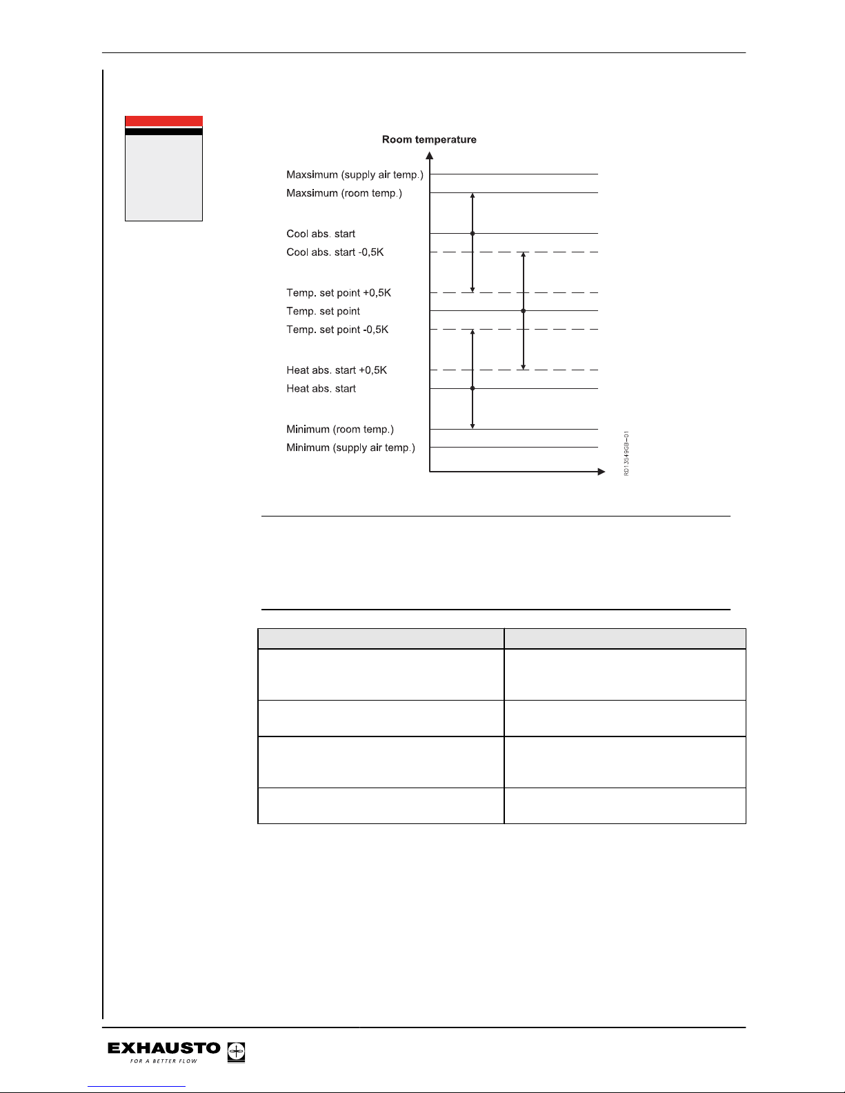
Menu 3.1.1.1.x - Room temperature regulation, absolute
Air setpoint >
Air setpoint,cool
Temp. setpoint >
Abs. / Rel. >
Cool rel. start >
Cool abs. start >
Heat rel. start >
Heat abs. start >
3.1.1.1.x xxxxxxx
60
80
21,0
Absolute
---
26,0
---
21,0
%
°c
°c
°c
NB Temp. setpoint can never be set closer to Heating abs. start or Cooling abs. start
than 0.5K.
Heating abs. start and Cooling abs. start can never be set closer to each other than
1K.
If the following will be adjusted....
Maximum room temp. is set to a value
lower than Cooling abs. start
Cooling abs. start will automatically reduce to the same value as Maximum
room temp.
Cooling abs. start is set to a value lower
than (Temp. setpoint + 0.5K)
Temp. setpoint will automatically reduce
to (Cooling abs. start - 0.5K).
Minimum room temp. is set to a value
higher than Heating abs. start
Heating abs. start will automatically rise
to the same value as Minimum room
temp.
Heating abs. start is set to a value higher
than (Temp. setpoint - 0.5K)
Temp. setpoint will automatically rise to
(Heating abs. start + 0.5K).
3003246-2014-05-21
Starting unit operation
30/100
Page 31
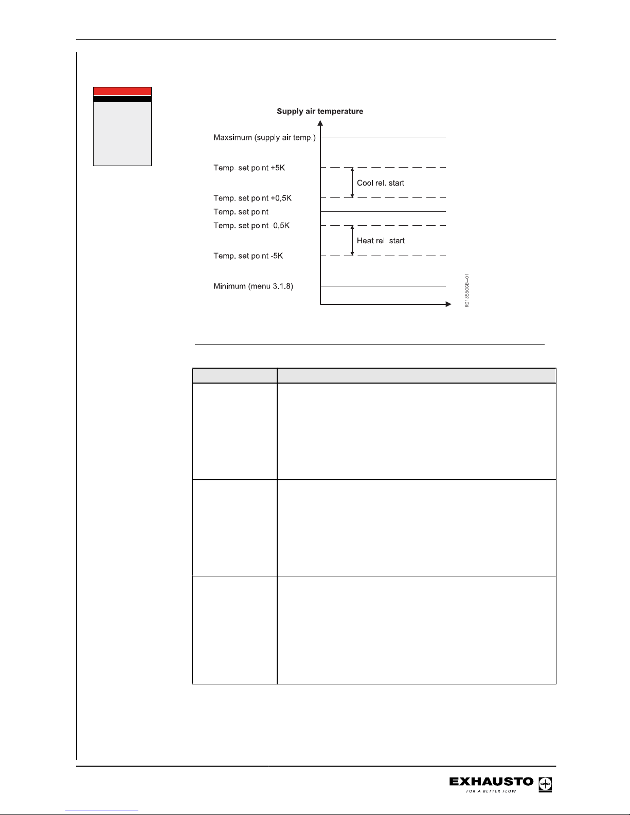
Menu 3.1.1.1.x - Supply air regulation, relative
Air setpoint >
Air setpoint,cool >
Temp. setpoint >
Abs. / Rel. >
Cool rel. start >
Cool abs. start >
Heat rel. start >
Heat abs. start >
60
80
21,0
Relativ
1,0
---
-1,0
---
%
%
°c
K
K
3.1.1.1.x xxxxxxx
If the following will be adjusted....
Maximum supply
air temp. is set to
a value lower than
(Temp. setpoint +
Cooling rel. start)
but higher than
(Temp. setpoint +
0.5K).
Cooling rel. start, automatically adjusted to (Maximum supply air
temp. - Temp. setpoint).
Maximum supply
air temp. is set to
a value lower than
(Temp. setpoint +
Cooling rel. start)
and less than
(Temp. setpoint +
0.5K).
Temp. setpoint automatically adjusted to (Maximum supply air
temp. - 0.5K).
And Cooling rel. start to 0.5K.
Minimum supply
air temp. is set to
a value higher
than (Temp. setpoint + Heating
rel. start) and
greater than
(Temp. setpoint -
0.5K).
Heating rel. start, automatically adjusted to (Minimum supply air
temp. - Temp. setpoint).
3003246-2014-05-21
Starting unit operation
31/100
Page 32
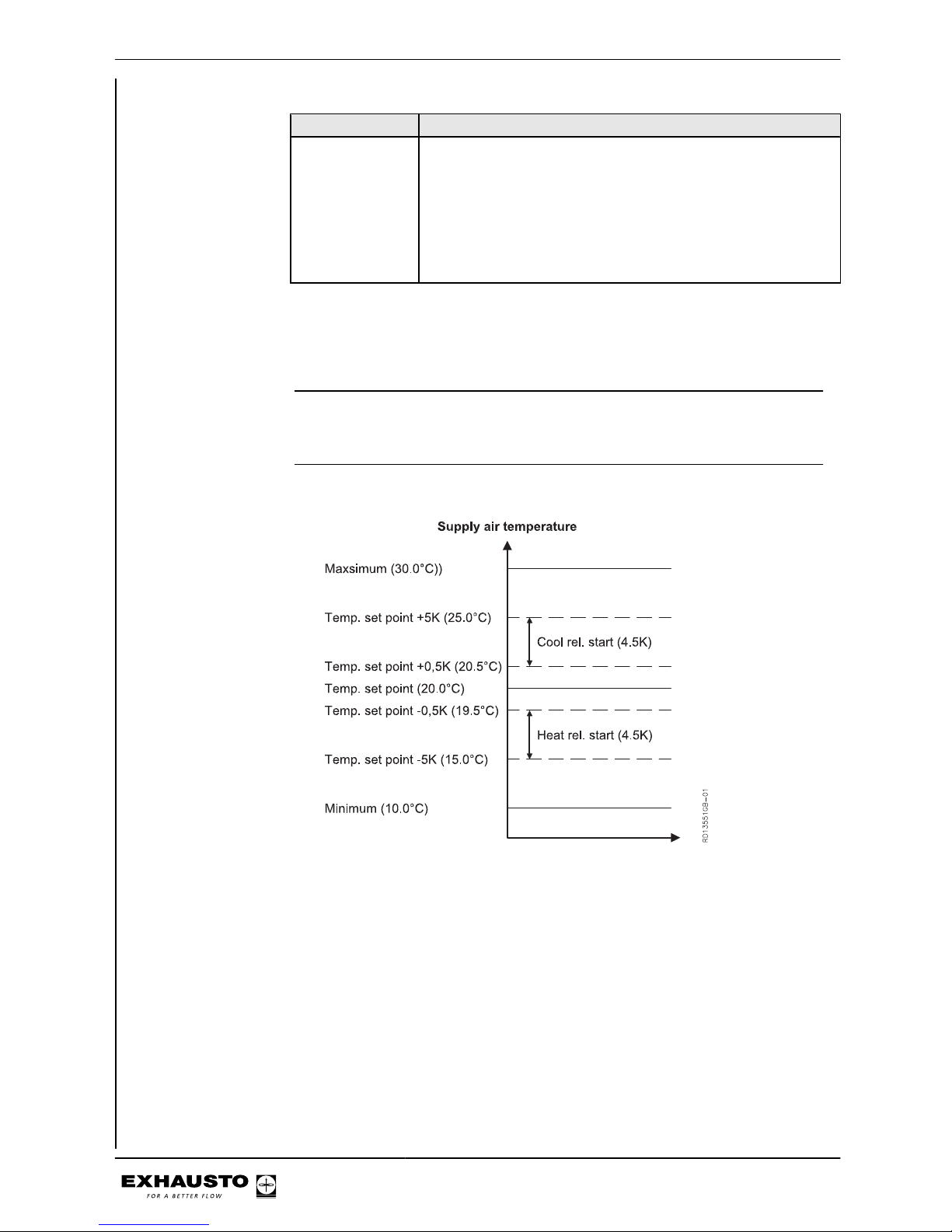
If the following will be adjusted....
Minimum supply
air temp. is set to
a value higher
than (Temp. setpoint + Heating
rel. start) and less
than (Temp. setpoint - 0.5K).
Temp. setpoint automatically adjusted to (Minimum supply air
temp. - 0.5K). And Heating rel. start to -0.5K.
Note for Cooling rel.
start
The absolute min./max. values for Cooling rel. start are from 0.5K to 5.0K. If (Maximum supply air temp. - Temp. setpoint) is less than 5.0K, the max. value for Cooling
rel. start is changed to (Maximum supply air temp. - Temp. setpoint).
Note for Heating rel.
start
The absolute min./max. values for Heating rel. start are from -5.0K to -0.5K. If (Minimum supply air temp. - Temp. setpoint) is greater than -5.0K, the min. value of
Heating rel. start is changed to (Minimum supply air temp. - Temp. setpoint).
Example 1: No limitation from Minimum and Maximum supply air temp.:
Example 2: Minimum and Maximum supply air temp. limit Cooling rel. start and Heating rel.
start:
3003246-2014-05-21
Starting unit operation
32/100
Page 33
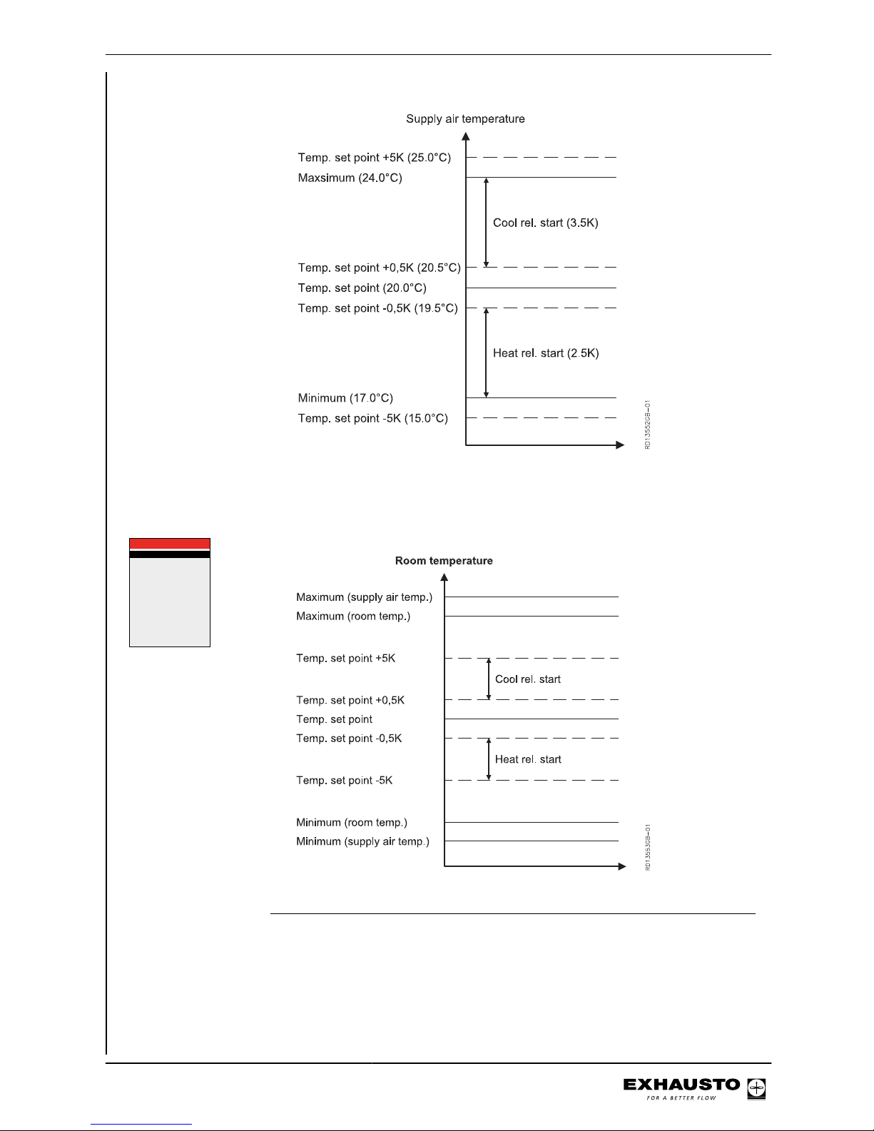
Menu 3.1.1.1.x - Room temperature regulation, relative
Air setpoint >
Air setpoint,cool >
Temp. setpoint >
Abs. / Rel. >
Cool rel. start >
Cool abs. start >
Heat rel. start >
Heat abs. start >
60
80
21,0
Relativ
1,0
---
-1,0
---
%
%
°c
K
K
3.1.1.1.x xxxxxxx
3003246-2014-05-21
Starting unit operation
33/100
Page 34
If the following
will be adjus-
ted....
Maximum room temp. is set to a value lower than (Temp. setpoint
+ Cooling rel. start) but higher than (Temp. setpoint + 0.5K).
Cooling rel.
start, automatically adjusted
to (Maximum
room temp. Temp. setpoint).
Maximum room temp. is set to a value lower than (Temp. setpoint
+ Cooling rel. start) and less than (Temp. setpoint + 0.5K).
Temp. setpoint
automatically
adjusted to
(Maximum
room temp. -
0.5K). And
Cooling rel.
start to 0.5K.
Minimum room temp. is set to a value higher than (Temp. setpoint
+ Heating rel. start) and greater than (Temp. setpoint - 0.5K).
Heating rel.
start, automatically adjusted
to (Minimum
room temp. Temp. setpoint).
Minimum room temp. is set to a value higher than (Temp. setpoint
+ Heating rel. start) and less than (Temp. setpoint - 0.5K).
Temp. setpoint
automatically
adjusted to
(Minimum
room temp. +
0.5K). And
Heating rel.
start to -0.5K.
Note for Cooling rel.
start
The absolute min./max. values for Cooling rel. start are from 0.5K to 5.0K. If (Minimum room temp. - Temp. setpoint) is less than 5.0K, the min. value of Cooling rel.
start is changed to (Maximum room temp. - Temp. setpoint).
Note for Heating rel.
start
The absolute min./max. values for Heating rel. start are from -5.0K to -0.5K. If (Minimum room temp. - Temp. setpoint) is greater than -5.0K, the max. value for Heating
rel. start is changed to (Minimum room temp. - Temp. setpoint).
Example 1: No limitation from Minimum and Maximum room temp.:
3003246-2014-05-21
Starting unit operation
34/100
Page 35
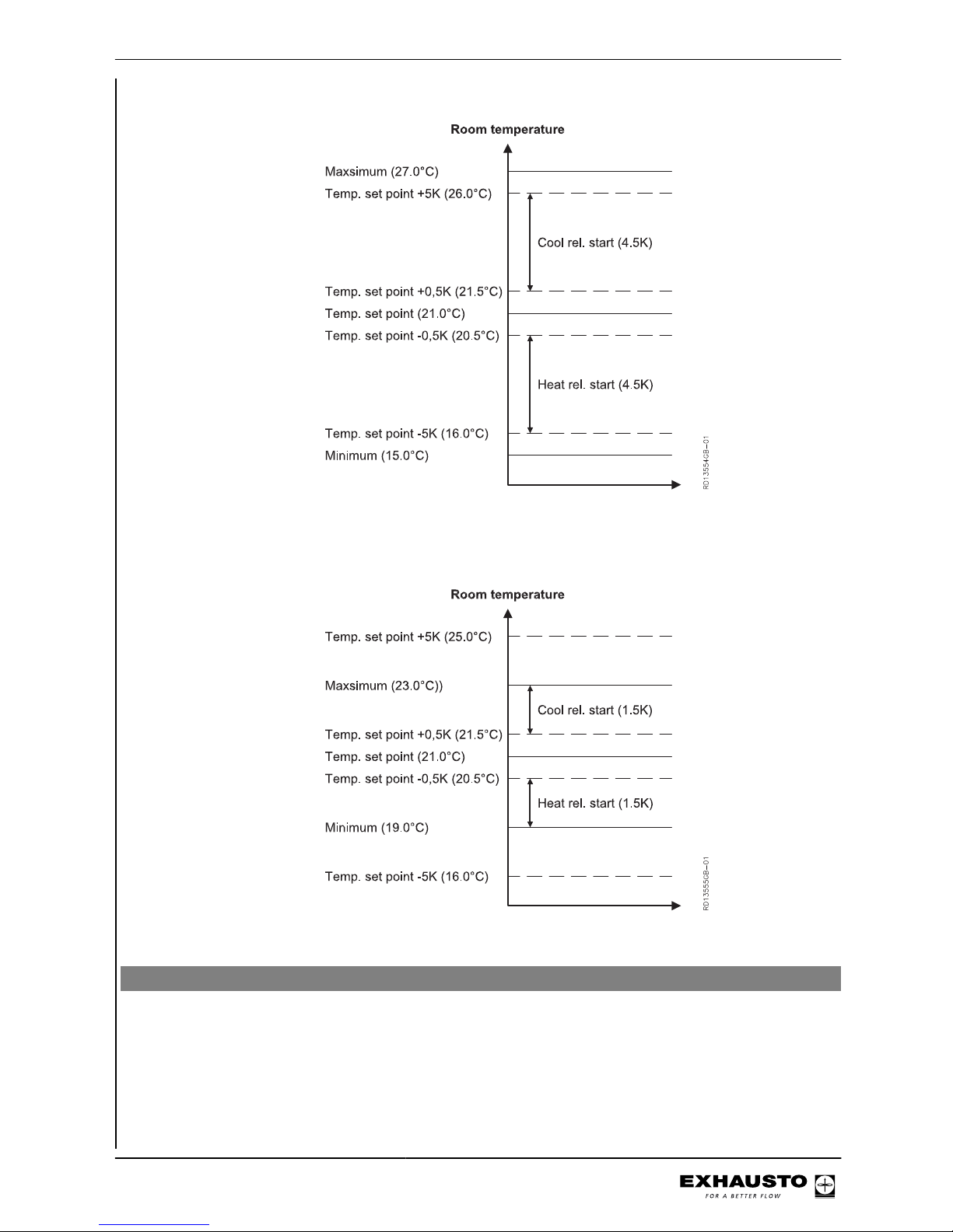
Example 2: Minimum and Maximum room temp. limit Cooling rel. start and Heating rel. start:
Menu 3.1.1 - Operation settings - Temperature regulation
Select one of two temperature regulation methods:
● Supply air temperature regulation
● Room temperature regulation (temperature regulated until the desired level is
reached)
Temperature regulation is adjusted serially, using the following elements:
3003246-2014-05-21
Starting unit operation
35/100
Page 36
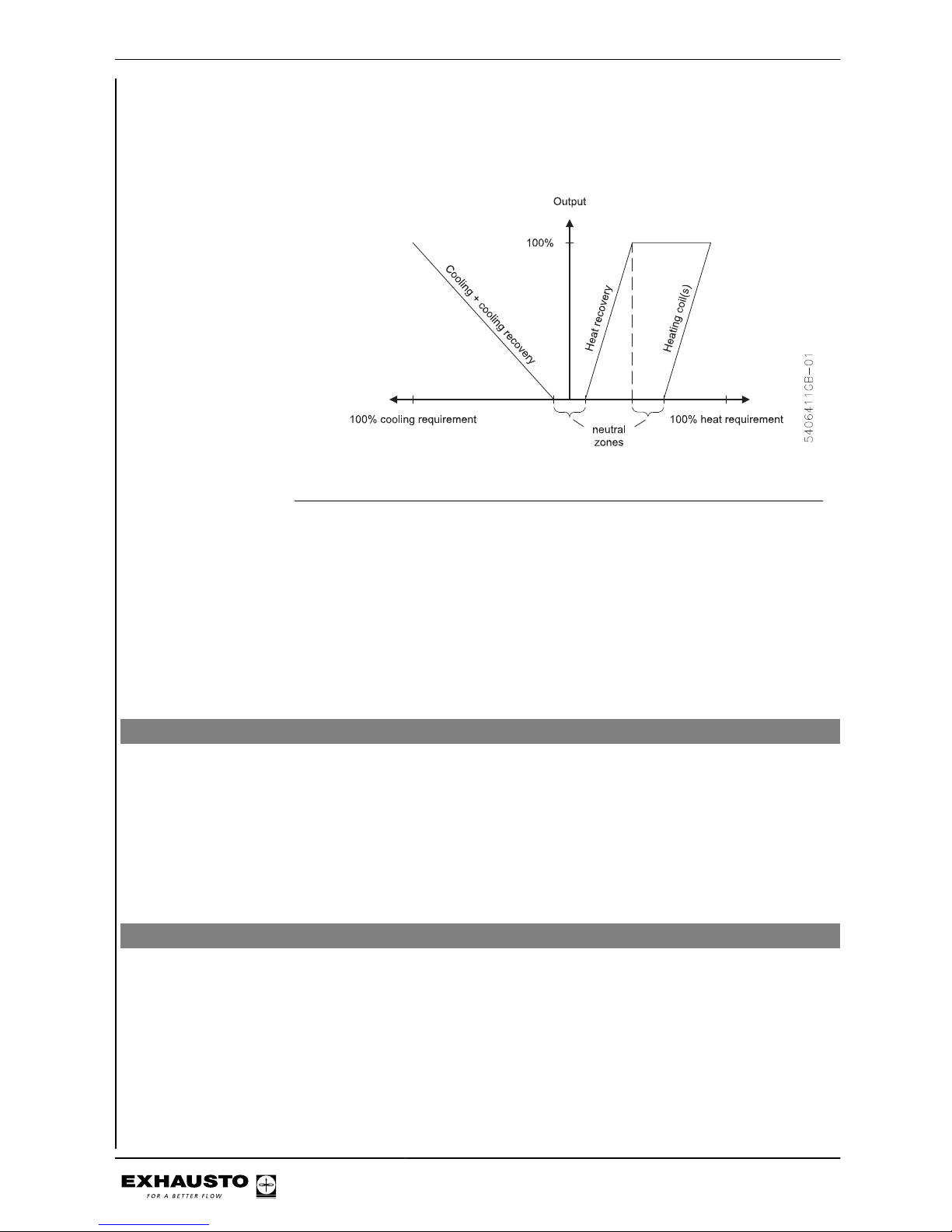
● Modulating heating coil(s).
● Modulating rotor speed
● Any external cooling unit and cooling recovery
Select Select one of the following:
● Supply air regulation - Typically used when the unit serves several rooms
with different loads (sunlight, people, machines). The temperature is regulated
by the built-in temperature sensor in the supply air spigot. If cooling and/or
heating coil(s) are fitted, temperature is regulated from the nearest temperature
sensor in the supply air duct.
● Room temperature control - Typically used when the unit serves several
rooms with similar loads. The temperature is regulated by the built-in temperature sensor in the extract air spigot or via an external duct or room sensor
(accessory).
Compensation
Compensation Each form of regulation provides different options for set point compensation. See
the next sections.
General Compensation of the airflow and temperature is carried out by a sensor sending
signals to the control system, which then reduces or increases airflow and temperature if required. Airflow and temperature are always compensated, no matter which
indoor air quality level the unit is set to.
Menu 3.1.2 - Air compensation
Airflow Compensation
Airflow compensation can be carried out on the basis of the following:
1. CO2 compensation - Air quality in room (CO2 content of air)
2. Humidity compensation - Air humidity in room
3. Airflow reduction - reduces airflow in case of falling supply air temperature
4. Outdoor compensation of airflow - reduces the airflow in case of falling out-
door temperature
3003246-2014-05-21
Starting unit operation
36/100
Page 37
NB ● All compensation options can be connected and active at the same time, and
may influence the control airflow
● CO2 and humidity compensation cannot be activated if air regulation method
8 is selected.
Autostart with timer
operation
If the weekly schedule is at OFF and either the CO2 or the humidity level exceeds
the starting limit for CO2 or humidity compensation, the VEX will automatically start
up using the settings from indoor climate level "Economy".
Menu 3.1.2.1 - CO2 compensation
Requirements A CO2 sensor (CO2B or other CO2 sensor via AI SPARE, MIO-CO2, BMS) must
be mounted to allow selection of CO2 compensation of the airflow. Connection of
the sensor is described in the additional instructions accompanying the sensor.
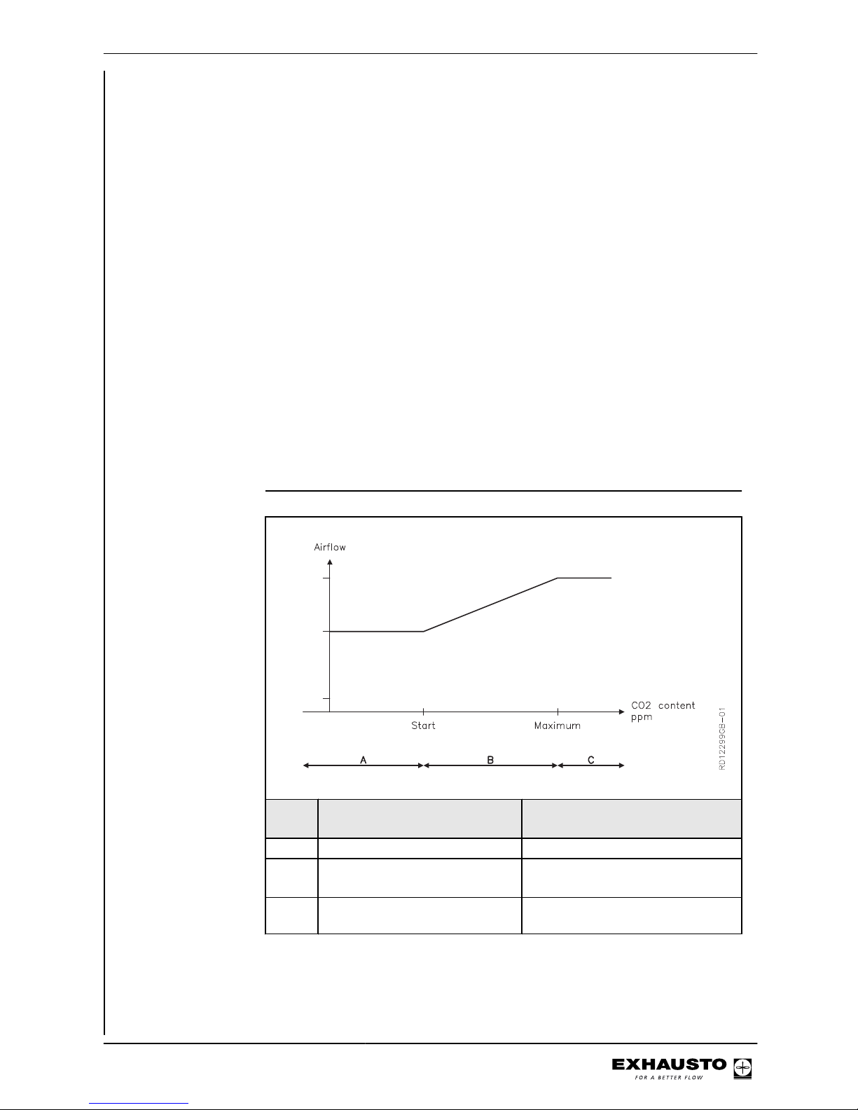
Function When the control system is operating, this function can be used to increase the
airflow in the event of increasing CO2 levels.
NB ● Cannot be activated if air regulation method 8 is selected
Selection of CO
2
compensation
Activate in Menu 3.1.3.2.
Example
CO2 concentration in the air
is ...
Airflow...
A less than Start is the same as set value
B between Start and Maximum increases gradually to a high level,
depending on the current CO2 level
C greater than Maximum is increased to maximum air re-
placement
3003246-2014-05-21
Starting unit operation
37/100
Page 38
Menu 3.1.2.2 - Humidity compensation of airflow
Requirements A humidity sensor (RHB, MIO-RH, BMS) must be fitted in order to be able to select
humidity compensation of the airflow. The sensor must be installed in the room in
which you wish to make compensation, such as a bathroom. Connection of the
sensor is described in the additional instructions accompanying the sensor.
Function When the control system is operating, this function increases airflow in the event of
increasing humidity levels.
NB ● Cannot be activated if air regulation method 8 is selected.
Selecting humidity
compensation
Activate in Menu 3.1.2.2.
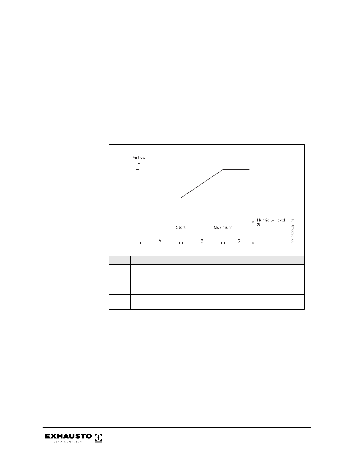
Example
Air humidity level is Airflow...
A less than Start is the same as set value
B between Start and Maximum increases gradually to a high value, de-
pending on the current air humidity (RH
level)
C greater than Maximum is increased to maximum air replace-
ment
Menu 3.1.2.3 - Airflow reduction
Function When the control system is operating, this function reduces the required supply air
airflow in the event of falling supply air temperature. This makes it possible to maintain the required supply air temperature longer.
Selecting airflow reduction
Activate in Menu 3.1.2.3.
3003246-2014-05-21
Starting unit operation
38/100
Page 39
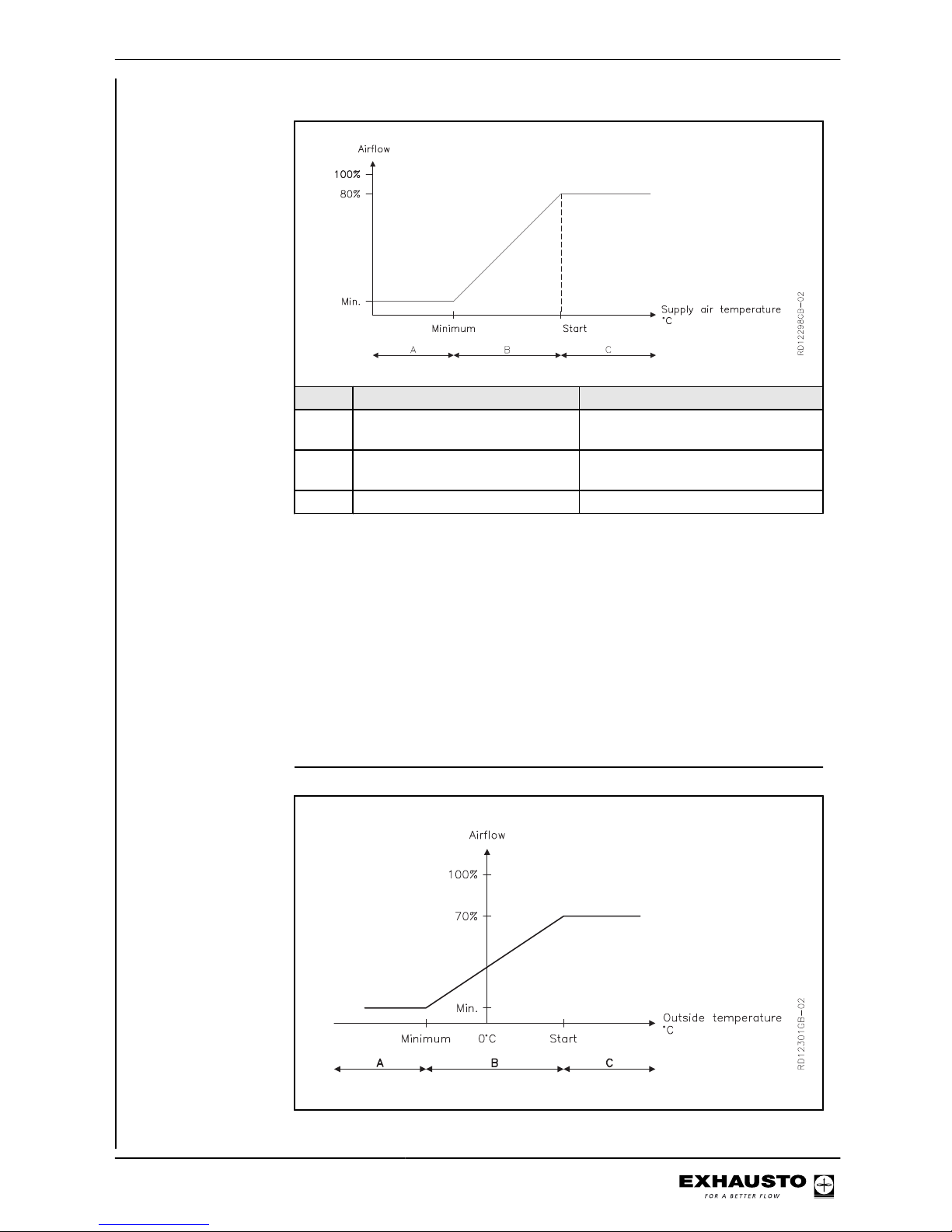
Example
Supply air temperature is Airflow...
A Lower than Minimum Equivalent to Minimum (or lowest)
airflow
B Between Minimum and Start increases gradually between mini-
mum airflow and the set airflow
C Greater than Start Equivalent to set airflow
NB ● When this function is active, a large imbalance can occur in the airflows, as
only the supply airflow is reduced while the extract airflow is maintained at the
required level
● CO2 and RH sensors are overridden by this function.
Menu 3.1.2.4 - Outdoor compensation of airflow
Function When the control system is operating, this function reduces the required airflow in
the event of falling outdoor air temperature.
Selecting outdoor
compensation
Activate in Menu 3.1.2.4.
Example
3003246-2014-05-21
Starting unit operation
39/100
Page 40
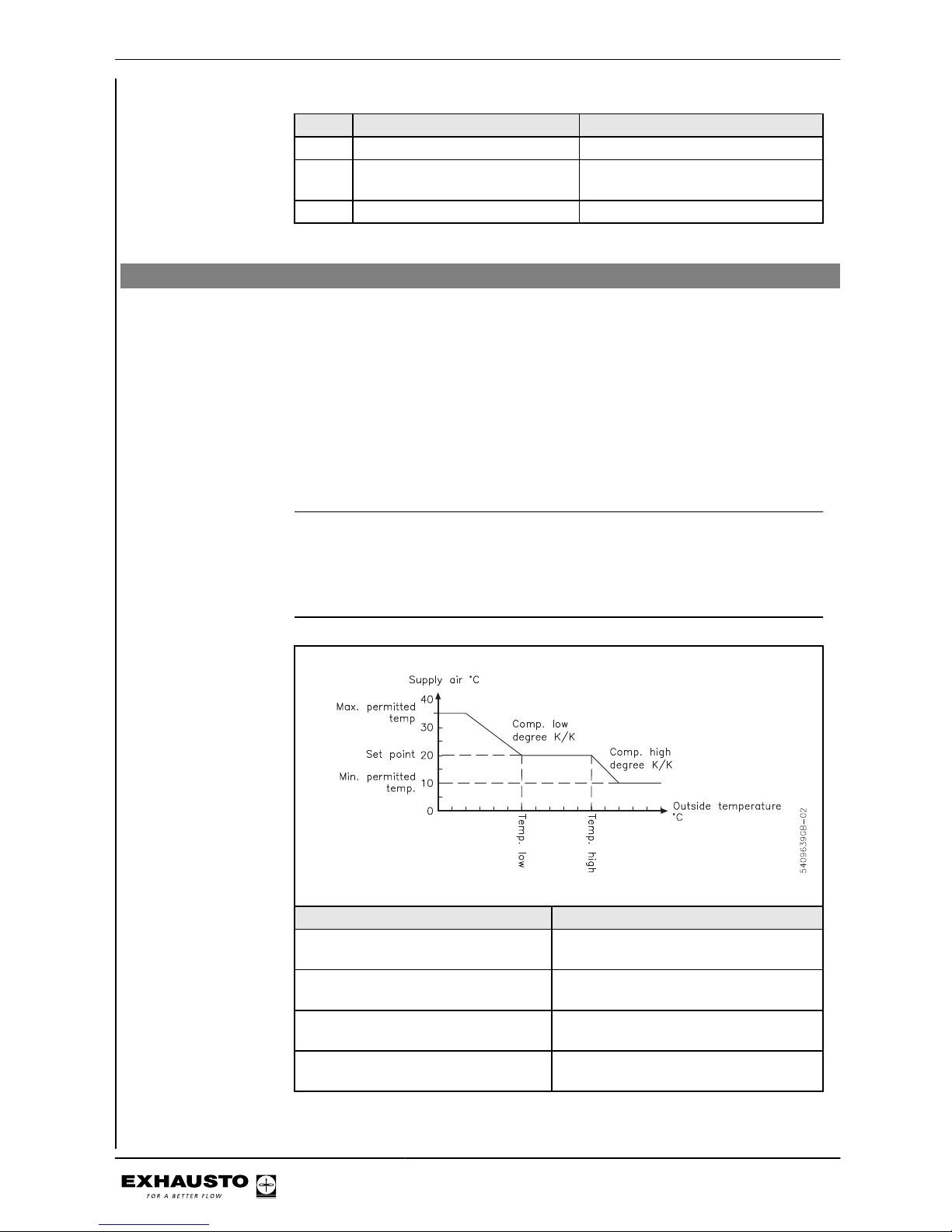
Outdoor air temperature is Airflow...
A Lower than Minimum Equivalent to Minimum airflow
B Between Minimum and Start increases gradually between mini-
mum airflow and the set airflow
C Greater than Start Equivalent to set airflow
Menu 3.1.3 - Temperature compensation
Outdoor air temperature compensation (menu 3.1.2.1)
Function The set point for the supply air temperature can be increased if outdoor air tem-
peratures are low. The supply air temperature can be lowered if outdoor air temperatures are high.
NB: This function is active only if supply air temperature regulation is activated for the
indoor air quality level in Menu 3.1.1 (Operation settings -> Temp. reg. -> Supply
air).
Selecting outdoor
air temperature
compensation
Activate in Menu 3.1.3.1.
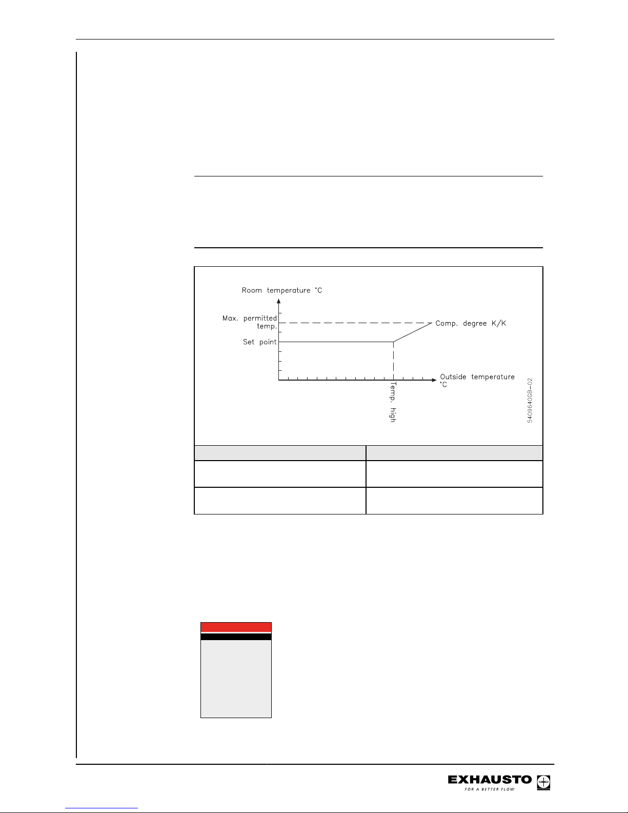
Outdoor air compensation
Outdoor air compensation aims to compensate for the energy that a building either
radiates when the outdoor air temperature is low, or absorbs when the outdoor air
temperature is high, thus maintaining a constant temperature in the building. If you
require outdoor air compensation, select values as indicated below.
Example
Supply air temperature is Action
Too cold when outdoor air temperature low
'Temp. low and/or "Comp. low' raised
Too warm when outdoor air temperature low
'Temp. low and/or "Comp. low' lowered.
Too cold when outdoor air temperature high
'Temp. high' and/or "Comp. high' raised
Too warm when outdoor air temperature high
'Temp. high' and/or 'Comp. high' lowered.
3003246-2014-05-21
Starting unit operation
40/100
Page 41
Summertime compensation (menu 3.1.2.2)
Function The room temperature can be raised if outdoor air temperatures are high.
NB: Summertime compensation is active only if room temperature regulation is activated
for the indoor air quality level in Menu 3.1.1 (Operation settings -> Temp. reg. ->
Room).
Selecting summertime compensation
Activate in Menu 3.1.3.2.
Summertime compensation
Summertime compensation raises the room temperature when the temperature
outside is high, to reduce the temperature difference people experience when entering and exiting the building. The result is that indoor air quality feels comfortable
even when people are wearing summer clothing. If summertime compensation is
required, select values as indicated below.
Example
Room temperature is Action
Too cold when outdoor air temperature
high
'Temp. high' lowered and/or "Comp.
grad' raised
Too warm when outdoor air temperature high
'Temp. high' raised and/or "Comp. grad'
lowered
Menu 3.1.4 + Menu 8.1 - Filter (monitoring in case of pressure)
General The pressure across outdoor air and extract air filters is monitored by sensors close
to the filters. A soiled filter will generate a warning signal, and then an alarm signal,
to indicate that it needs replacing.
3.1.4 Filter
Current pressure:
Outdoor air
Extract air
Warning:
Outdoor air >
Extract air >
Alarm:
0 Pa
0 Pa
135 Pa
135 Pa
Outdoor air >
Extract air >
150 Pa
150 Pa
Current pressure The current pressure drop across the outdoor air and extract air filters is displayed.
3003246-2014-05-21
Starting unit operation
41/100
Page 42
Warning Set the supply air and extract air soiled-filter warning level here.
Alarm Set the outdoor air and extract air replace-filter alarm level here.
Menu 8.1 The same settings that can be configured in Menu 3.1.4 can be configured here.
Menu 3.1.4 + Menu 8.1 - Filter (monitoring with hour counter)
General Filter changes are monitored by an operating hours counter and indicated in whole
days.
Operating days:
Warning >
Alarm >
Change of filter >
Last changed:
Date
3.1.4 Filter
51d
80d
100d
No
14-10-2011
Operating days
since change
This shows the number of operating days since the last filter change
Warning This is where the number of operating days is set which must elapse before an
alarm on incipient filter soiling in the outdoor air and extract air filters is signalled.
The factory setting is 100 days.
Alarm This is where the number of operating days is set which must elapse before an
alarm for changing the outdoor air and extract air filters is signalled. The factory
setting is 100 days.
NB: When the warning is set to the same number of days as the Alarm, the system will
not signal a warning.
Filter change In the case of filter change, select "Yes", and the date for filter change will be saved
and the operating hours counter will be zeroised.
Menu 8.1 The same settings that can be configured in Menu 3.1.4 can be configured here.
Menu 3.1.5 - Night-time cooling
Function Night-time cooling is typically used during hot summer periods in buildings which
are unoccupied during the night. During hot periods it may be desirable to cool down
the building during the night. The aim is to reduce the energy required for cooling
during the day by exploiting the lower night-time temperature combined with high
air replacement. Night-time cooling involves high airflow ventilation, without turning
on the cooling unit.
Conditions for
night-time cooling
The control system does a five-minute "test run" to check the following conditions
are met before activating the night-time cooling function:
3003246-2014-05-21
Starting unit operation
42/100
Page 43
● Outdoor air temperature must be lower than the room temperature
● Prior to initiating night-time cooling, there must not have been any heating re-
quirement within a time interval defined in the night-time cooling menu
● Heating coils and rotor operation must not be active during night-time cooling
(does not apply during the test run)
● As a factory default setting (set in Menu 3.1.5.9 Operation blocking), the nighttime cooling function can only be activated if Comfort operation is scheduled
for the following day
● Extract air temperature must be higher than the set point
Conditions not met If the above conditions are not met at the Start time, the control system will perform
a test run once an hour (until an hour before the Stop time) to check whether the
conditions for starting night-time cooling can now be met.
Override The following can override the night-time cooling function:
● If the system is controlled by a PIR sensor
● If the Manual indoor air quality level is active
NB: for third-party
equipment with
damper
If third-party equipment with damper is fitted to the unit, check
that this does not impeded air replacement when night-time cooling is activated!
3003246-2014-05-21
Starting unit operation
43/100
Page 44
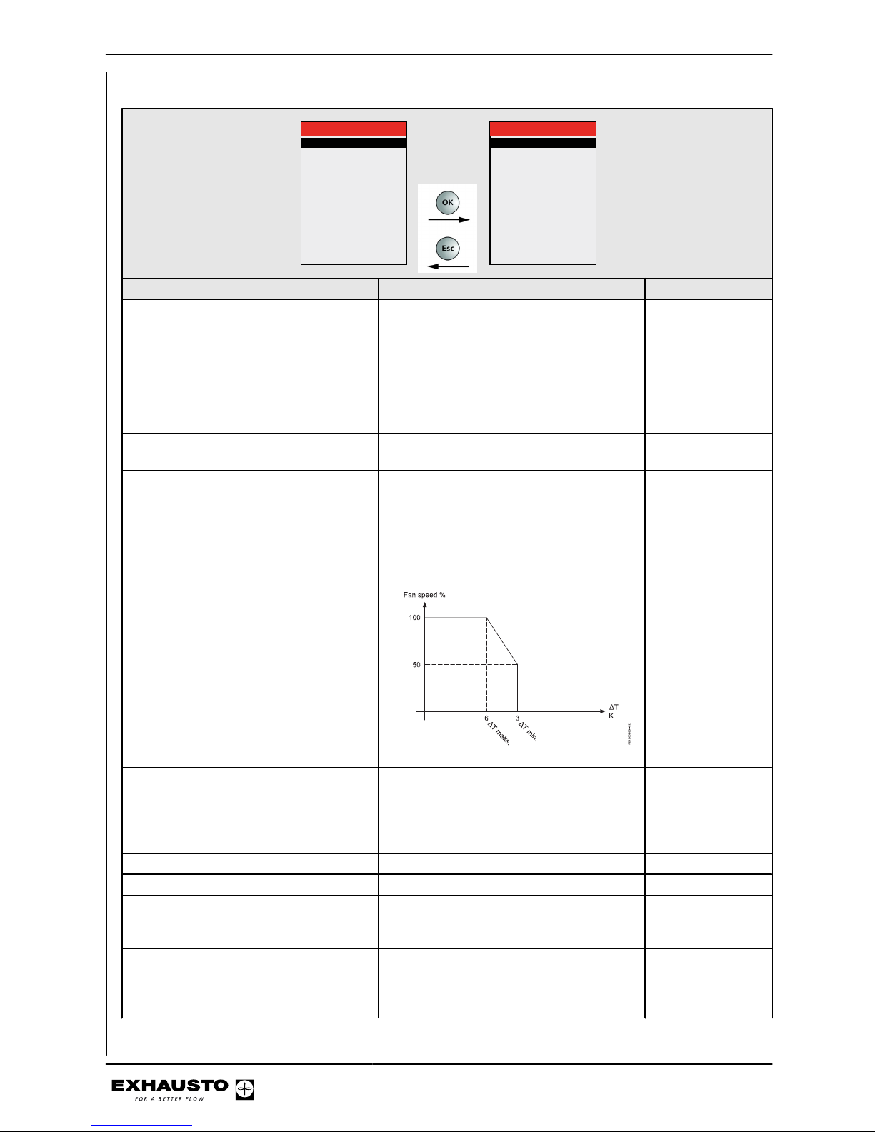
3.1.5 Night-time cooling
Active period >
Set point >
Min. supply temp. >
ΔT max. >
ΔT min. >
Start time >
Stop time >
HC blocking >
Permit night-time cooling >
Summer
18°C
10°C
6K
3K
00:00
06:00
60hr
3.1.5.9 Permit night-time cooling
Comfort >
Standby >
Economy >
Yes
No
No
Lines in Menu 3.1.5 Function Factory setting
Operating period ● Select "None" to deactivate night-time
cooling.
● Select "Always" to activate night-time
cooling all year round.
● Select "Summer" to activate night-time
cooling during summertime. See summer/wintertime icon on the front of the
HMI.
Summer
Set point Set point for desired room temperature dur-
ing night-time cooling
18°C
Min. supply air temp. If the selected minimum supply air temper-
ature cannot be met, night-time cooling
stops
10°C
ΔT max. Setting for temperature difference between
outdoor air and extract air*, when the unit
operates with 100% fan speed.
6K
ΔT min. Setting for temperature difference between
outdoor air and extract air*, when the unit
operates with 50% fan speed. From ΔTmin.
to ΔTmax. the fan speed increases from
50% to 100%.
3K
Start time Start time for night-time cooling 00:00
Stop time Stop time for night-time cooling 06:00
HC blocking (heating coil blocking) Time interval prior to night-time cooling dur-
ing which there must not have been any
heating requirement
60 hr
Permit night-time cooling Menu 3.1.5.9 is used to configure condi-
tions under which night-time cooling is activated. This menu is dependent on the timer program for the following day
Comfort > Yes
Standby > No
Economy > No
3003246-2014-05-21
Starting unit operation
44/100
Page 45
*The extract air temperature is always used, regardless of whether a room temperature
sensor is installed for the system.
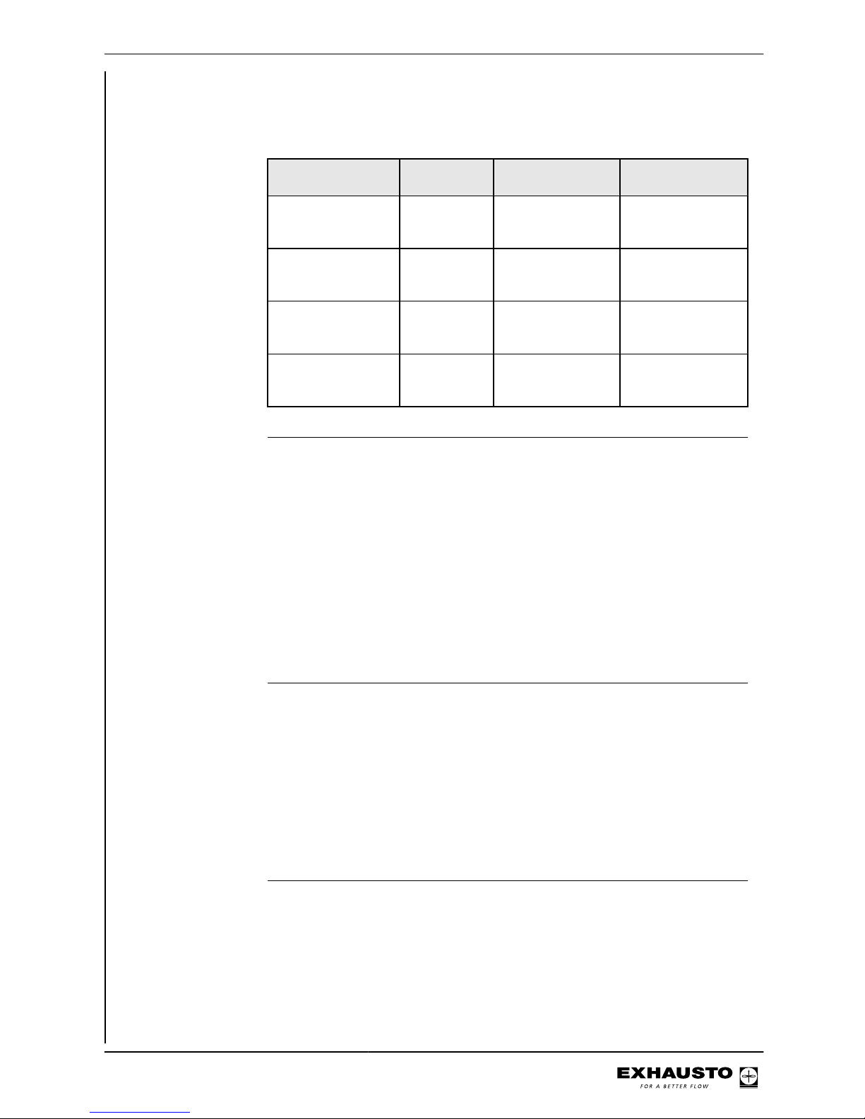
Menu 3.1.5.9 - Permit night-time cooling
If is set to and the indoor air
quality level is
is activated
Comfort/Standby/
Economy
Yes included in the tim-
er program for the
following day
night-time cooling
Comfort/Standby/
Economy
Yes not included in the
timer program for
the following day
no night-time cooling
Comfort/Standby/
Economy
No included in the tim-
er program for the
following day
night-time cooling
Comfort/Standby/
Economy
No not included in the
timer program for
the following day
night-time cooling
Menu 3.1.6 - Cold recovery
Selecting cold re-
covery
Activate in Menu 3.1.6.
Start-up (Start limit) Cold recovery starts when the configured temperature difference between the room
temperature and outdoor air temperature is reached. The factory setting is 3K. Cold
recovery operates at 100% when it is engaged.
Stop Cold recovery ceases again when the temperature difference between the room
temperature and outdoor air temperature is 1K below the configured start limit.
Operation with CCW
or MXCU
Recommend that cooling recovery is activated if CCW or MXCU cooling used.
Menu 3.1.7 - Fan limits
Function Configuration of minimum and maximum fan output limits (supply air and extract
air) as percentages. These are the absolute minimum and maximum fan output
limits, i.e. all other menus where fan output can be changed will be limited by the
absolute settings.
Example If a user selects maximum fan rpm in the user menu (100% ventilation), fan output
will still never exceed the value set in this menu.
Menu 3.1.8 - Temperature limits for supply air and room
Function Configuration of minimum and maximum supply air temperature limits. These are
the absolute minimum and maximum supply air temperature limits, i.e. all other
menus where supply air temperature can be changed will be limited by the absolute
settings.
3003246-2014-05-21
Starting unit operation
45/100
Page 46
Example If a user selects maximum temperature in the user menu, the temperature will never
exceed the value set in this menu.
Supply air temperature limits
Setting Go to menu NB
Lowest permitted supply air temperature
3.1.8 Range: 10.0℃...25.0°C
Highest permitted supply air temperature
Range: 30.0℃...40.0°C
NB The settings above must only be changed if special circumstances require
this. Otherwise, the factory settings can be used.
Room temperature limits
Function Configuration of minimum and maximum room temperature limits. These are the
absolute minimum and maximum room temperature limits, i.e. all other menus
where room temperature can be changed will be limited by these settings.
Example If a user selects maximum temperature in the user menu, the temperature will never
exceed the value set in this menu.
Room temperature
limits
Setting Go to
menu
NB
Lowest permitted room
temperature
3.1.8 Range: 10.0℃...34.0°C
Highest permitted room
temperature
Range: 11.0℃...35.0°C
ΔT (difference between supply
air and extract air temperature)
Allows for prevention of condensation on supply air
fixtures and down draught. Range: ΔT: 2.0K...15.0K
NB The settings above must only be changed if special circumstances require
this. Otherwise, the factory settings can be used.
Menu 3.1.9 - Cooling/heat pump unit
Min. COP >
VP drift-lav COP >
1.0
---
3.1.9 Køle-/VP. Unit
3003246-2014-05-21
Starting unit operation
46/100
Page 47
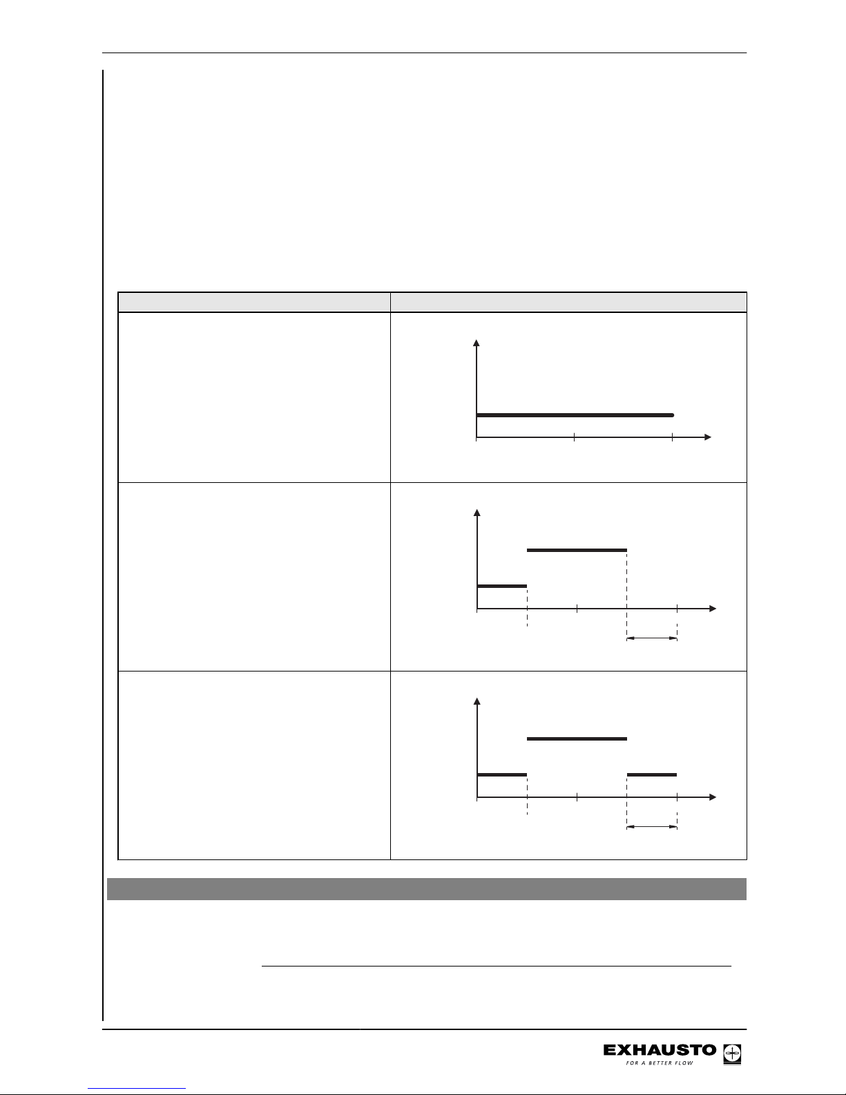
Min. COP Selection of desired efficiency level (COP) for heat pump operation (0.5 - 5) or de-
selection of heat pump operation (OFF). See menu guide for recommended default
values for heating coil.
Heat pump operation - low COP
The menu is only active if a heating coil is configured.
If "On" is selected in the menu, further operation of the heat pump will be permitted
even if the heating coil output is at 100% (see example 3)
Examples
Examples Output requirement heating [%]
1. Heat pump only (default = 1.0)
Heating coil
Heat pump
RD13632GB-01
100%50%0%
2. Heat pump and heating coil (default:
HCE=1.0 - HCW=2.5. Heat pump operation
- low COP "Off")
A - Output limited by heat pump's efficiency
limit.
B - Higher operating output from heat pump
has been deselected. The desired heat requirement cannot be met.
Heating coil
Heat pump
RD13633GB-01
100%50%0%
BA
100%0%
3. Heat pump and heating coil (default:
HCE=1.0 - HCW=2.5. Heat pump operation
- low COP "On")
A - Output limited by heat pump's efficiency
limit.
B - Heat pump in operation again at a lower
efficiency. This is permitted when the heating
coil output is at 100%.
Heating coil
Heat pump
RD13634GB-01
100%50%0%
BA
100%0%
Menu 5 - Time and weekly plan
Menu 5.1 - Date and time
This menu is used to set the current date, day and time.
3003246-2014-05-21
Starting unit operation
47/100
Page 48

Menu 5.2 - Weekly plan
Plan type When "Timer" operation has been selected in Menu 1, the weekly plan must be
configured. Select one of the following three plan types:
Plan type Use when Program interval
Day Different programs are re-
quired for different weekdays.
Monday, Tuesday, Wednesday, Thursday, Friday, Saturday, Sunday
Week The same program is required
for all days of the week.
Monday to Sunday
5/2 One program is required for
Monday to Friday, and another program for weekends.
Weekdays: Monday to Friday,
Weekend: Saturday and Sunday
Editing
5 Time and weekly plan
Date and time >
Weekly plan >
5.2 Weekly plan
Plan type >
Change >
5/2
5.2.2 Change
Weekday >
Weekend >
5.2.2.1 Weekday
1 IAQ. level >
1 Time of day >
2 IAQ. level >
2 Time of day >
3 IAQ. level >
3 Time of day >
4 IAQ. level >
4 Time of day >
5 IAQ. level >
5 Time of day
Standby
06:00
Comfort
07:30
Economy
17:30
OFF
00:00
Inactive
--:--
Menu Action
5.2 Select "Weekly plan"
5.2.2 Select "Editing"
● If plan type "Week" is selected start editing in Menu 5.2.2
● If plan type "Day" or "5/2" is selected Go to Menu 5.2.2.1 and start editing
5.2.2 or 5.2.2.1 Go to 1 Indoor air quality level - select
level. Select one of the following: Inactive, OFF, Comfort, Standby,
Economy
Go to 1 Time - Select the start time
for indoor air quality level 1
Complete the rest of the program in
the same way. See programming example below
3003246-2014-05-21
Starting unit operation
48/100
Page 49
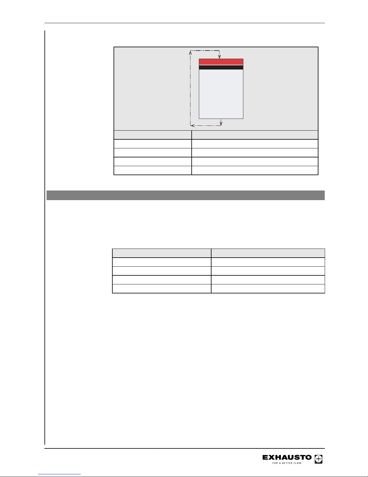
Program example
5.2.2.1 Weekday
1 IAQ. level >
1 Time of day >
2 IAQ. level >
2 Time of day >
3 IAQ. level >
3 Time of day >
4 IAQ. level >
4 Time of day >
5 IAQ. level >
5 Time of day
Standby
06:00
Comfort
07:30
Economy
17:30
OFF
00:00
Inactive
--:--
Time interval Indoor air quality level
06:00 - 07:30 Standby
07:30 - 17:30 Comfort
17:30 - 00:00 Economy
00:00 - 06:00 OFF
Menu 7 - Safety functions
Menu 7.1 - Fire alarm
Four operating
modes
There are four different operating modes in the event of a fire. The selected operating mode must meet regulatory standards.
Go to Menu 7.1 and select mode Operating mode
1 (factory setting) Supply air and extract air stopped
2 Supply air 100% and extract air stopped
3 Supply air stopped and extract air 100%
4 Supply and extract air 100%
Activation of operating mode
The selected operating mode under the function "Fire alarm" is activated if the
closed circuit in any of the two inputs (BT40/50 and BT70 on the connection board)
are broken.
The inputs allow the connection of:
● Smoke detectors
● Fire thermostats (e.g. BT40, BT50 or BT70)
● BMS
● Fire control system
If an input is not used, a jumper must be used (see Electrical Installation Guide)
3003246-2014-05-21
Starting unit operation
49/100
Page 50
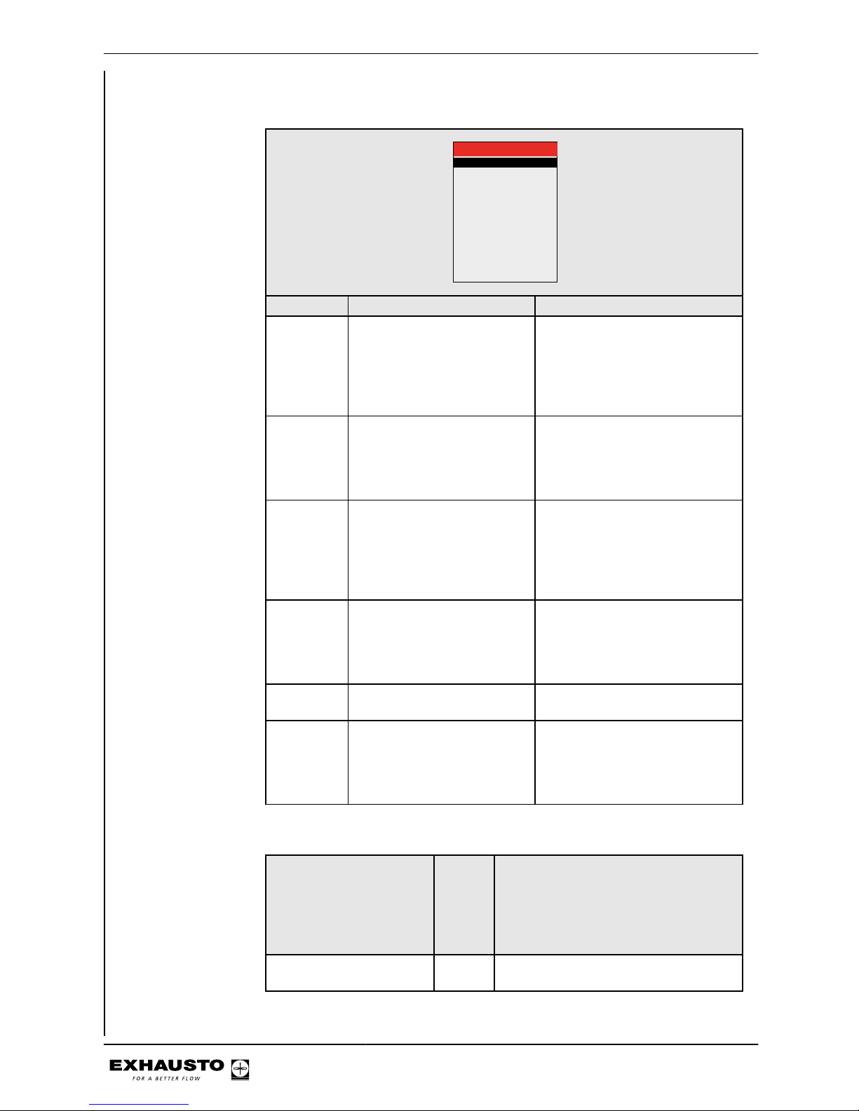
Menu 7.2 - Frost protection of HCW
Setting of frost pro-
tection
7.2 Frost protection HCW
Stop temperature >
Warning temp. >
Number of restarts >
Heat retention >
RPT-X fitted >
15°C
2,0K
2
22°C
No
Menu line Function Action
Stop tem-
perature
Selection of return water temperature setting at which the
unit stops and the motor valve
fully opens. See table below
● Select the required stop temperature
The coldest temperature sensor
(TE-RPT or TE-RPT-X) will be utilised. See the temperatures in
Menu 2.6
Warning
tempera-
ture
Selection of return water temperature setting at which airflow is reduced
● Select the temperature relative to the stop temperature
(ΔT) which will generate a
frost damage warning and reduce airflow
Number of
restarts
Up to five restarts may be selected
● Select the maximum number
of restarts permitted in an
hour before an alarm is triggered
Manual reset is activated by selecting “0” for no. of restarts
Constant
tempera-
ture
In the case of a unit being
stopped, a selected "constant
heating temperature" is maintained to ensure that the heating pipes stay warm.
● Select the required constant
heating temperature
RPT-X fit-
ted
State if RPT-X is fitted ● If an RPT-X is not required, it
may be removed
MVM/CP
time
Time before MVM valve
closes and circulation pump
stops when stop temp. or number of restarts has been exceeded.
● Options:
- 5 minutes
- ∞ (never)
Stop temperature
If the return water tem-
perature does the follow-
ing within a five-minute
period
and to-
tal
num-
ber of
re-
starts
Response
Rises above the constant
heating temperature
> 0 Airflow is increased again to the normal
operating level
3003246-2014-05-21
Starting unit operation
50/100
Page 51
If the return water tem-
perature does the follow-
ing within a five-minute
period
and to-
tal
num-
ber of
re-
starts
Response
Remains below the constant heating temperature
> 0 5 min: After 5 minutes, the MVM valve will
close and the CP will stop. The alarm
must be reset manually in menu 4.
∞
: MVM valve 100% open and circula-
tion pump continues operation.
NB The frost protection function is only active when the outdoor air temperature is below
10°C.
Menu 7.3 Cooling/
heat pump unit
Afisningstryk >
Balance komp. >
Frostsikring >
45
Til
-5.0%°c
7.3 Køle-/VP. Unit
Adjustment of deicing pressure
In the menu, select the increase in pressure loss as a percentage (relative to dry
coil) that must activate de-icing. The de-icing pressure can be set between 25 80%. It is recommended that the factory-set de-icing pressure of 45% (based on
experience) should only be changed in special circumstances.
Balance compensation
Air balance is overridden to 1:1.15 if the cooling/heat pump unit is at the limit of its
operating range.
Frost protection The safety function is only active when the unit is operating with
heat pump.
Adjustment of minimum temperature for liquid in exhaust water circuit. Adjusted according to the glycol mixture, see frost protection table for Ethylene glycol mixture in
Cooling/heat pump instructions.
3003246-2014-05-21
Starting unit operation
51/100
Page 52
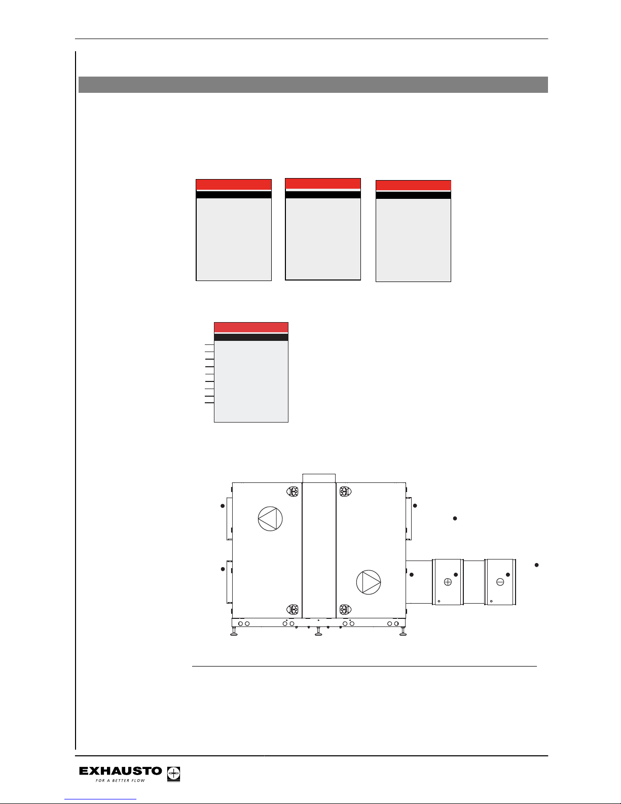
5. Operation
Menu 2 - Operating readings
General
All of the operating parameters can be read in Menu 2. _ _ _ is shown in the menu if a
given unit is not fitted.
Menu 2.1 - Air temperatures
2 Operating readings
Air temperature >
Airflows >
MC parameters >
Temp. reg. units >
Pressure >
Heating coil >
Cooling/heat pump unit
CCW
CU cooling unit >
MXCU
Timers
CO2/RH sensorer >
2.1 Air temperature
Setp. regulators >
Supply air (room)
Extract air (room)
Outdoor air
Exhaust air
Supply air (VEX)
Supply air (CU)
Room sensor
Heating coil
Cooling unit
21,3
11,2
15.7
0,0
18,5
--0,0
0,0
---
°c
°c
°c
°c
°c
°c
°c
2.1.1 Setp. regulators
Room
Heat recovery
Cooling unit
Heating unit
Compensation:
Outdoor temp.
Summer
0,0
10,0
10,0
10,0
Inactive
Inactive
Temperature sensor
positioning VEX200 example
11,2°c
2.1 Air temperature
Setp. regulators >
Supply air (room)
Extract air (room)
Outdoor air
Exhaust air
Supply air (VEX)
Room sensor
Heating coil
---Cooling unit
21,3°c
15,7°c
0,0°c
18,5°c
0,0°c
0,0°c
Supply air (CU)
---
A
B
C
D
E
F
G
H
J
*)
*Measured if room sensor TS-ROOM or if the duct sensor TS-DUCT is fitted.
D
C
G
E
H
J
B
RD12319-02
A
3003246-2014-05-21
Operation
52/100
Page 53
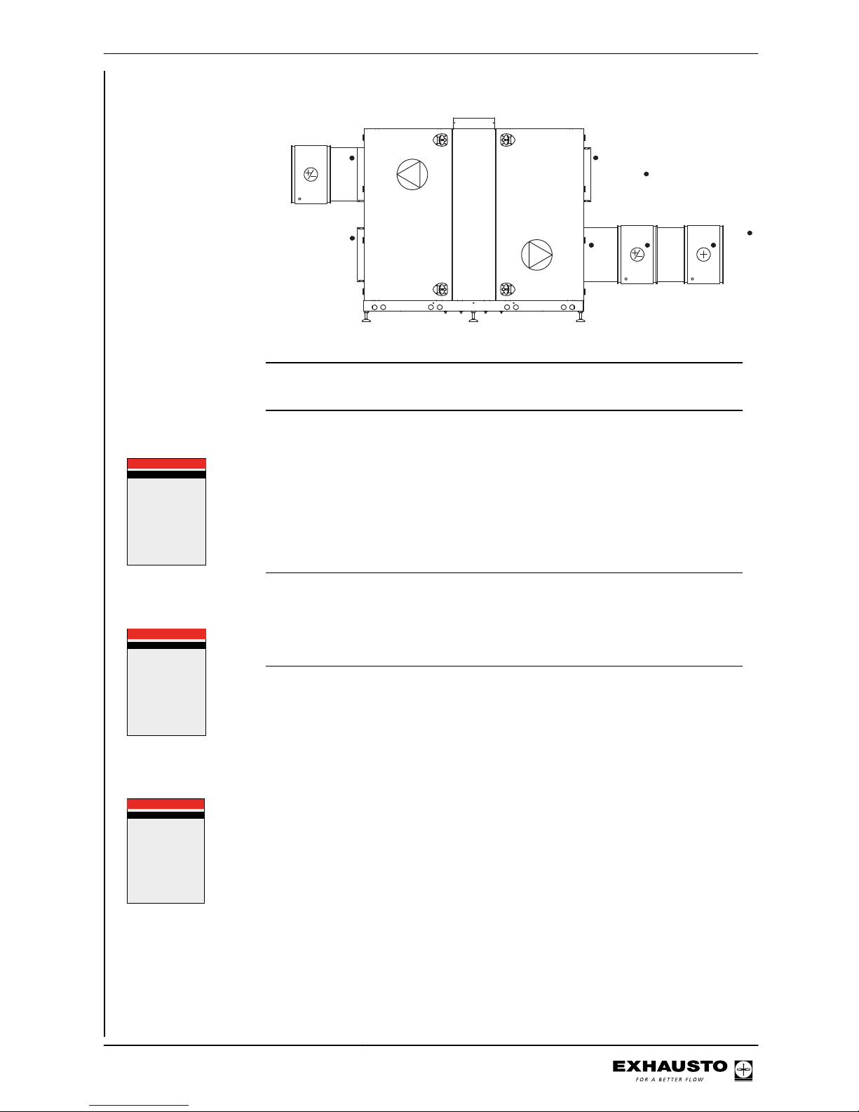
Example VEX200 +
Chiller
D
C
G
E
H
J
B
RD13586-01
A
Diagrams See appendix 1 for VEX200 diagrams.
Menu 2.1.1 - Set points for regulators
2.1.1 Setp. regulators
Room
Heat recovery
Cooling unit
Heating unit
Compensation:
Outdoor temp.
Summer
0,0
10,0
10,0
10,0
Inactive
Inactive
This menu shows set points for:
● Room temperature regulator
● Heat recovery regulator
● Cooling regulator
● Heating unit regulator
Compensations:
● List of compensations (active/inactive)
Menu 2.2 - Airflows
2.2 Airflows
Supply air
Supply air
Extract air
Extract air
3150l/s
11340m³/h
3225l/s
11610m³/h
The menu shows the airflows (converted to airflows at 20°C) specified in l/s and
m3/h.
Menu 2.3 - Motor controller parameters (MC parameters)
2.3 MC parameters
Supply air:
Maximum
Set point
Minimum
Extract air:
Maximum
Set point
Minimum
50.0Hz
30.0Hz
14.0Hz
50.0Hz
30.0Hz
14.0Hz
FC: The menu shows maximum and minimum frequencies. The set point shows the
frequency at the current ventilation level (e.g. 30 Hz).
3003246-2014-05-21
Operation
53/100
Page 54
Menu 2.4 - Temperature regulating units
2.4 Temp. reg. enheder
Varmegenv.
Eftervarmefl.
VP enhed
Køleenhed
Kølegenvinding
0.0
0.0
0.0
0.0
0.0
%
%
%
%
%
The menu shows the current:
● heat recovery
● Output of heating coil (if installed)
● Output of heat pump unit (if installed)
● Output of cooling unit (if installed)
● Cold recovery (0% or 100%)
Menu 2.5 - Pressure
2.5 Pressure
External pressure:
Supply air duct
Extract air duct
Filter pressure:
Outdoor air filter
Extract air filter
CCW exhaust
0
0
0
0
0
Pa
Pa
Pa
Pa
Pa
The menu shows:
● External pressure in supply air and extract air duct (if MPT-DUCT installed)
● Pressure loss across supply air and extract air filters
● pressure drop across CCW coil in exhaust duct
Menu 2.6 - Heating coil
NB The menu displays depend on whether a water heating coil or an electric heating
coil is installed as a heating unit (see Menu 3.4 Accessories).
Water heating coil
2.6 Heating coil
Water heating coil:
Supply
Return
External return
Heat retention
Pump
25.0
15.0
15.0
0
Off
°C
°C
°C
%
The menu shows:
● supply water temperature
● return temperature
● external return water temperature (coldest)
● constant temperature - if the constant temperature function is active (specified
as a percentage)
● pump - if the circulation pump in the heating cycle is in operation
Electric heating coil
Electric heating coil:
Power step total
Active power steps
Setpoint
TSA60/80
2.6 Heating coil
1
0
0.0
25.0
%
°C
The menu shows:
● number of power steps in heating coil
● Number of active power steps
● output of the modulating step
● internal temperature in electric heating coil control box
3003246-2014-05-21
Operation
54/100
Page 55
Menu 2.7 - Cooling/heat pump unit
Trykgas tryk
Sugegas tryk
Trykgas temp.
Fremløb
Luftmæng. øget
Balance
Reduktion
Blok start
Tryktabsstigning
CH størrelse
0.00
0.00
0.00
0.00
Nej
Ja
0
Ja
0
---
bar
bar
°c
°c
%
%
2.7 Køle-/VP. Unit
The menu shows:
● Pressure gas pressure
● suction gas pressure
● pressure gas temperature
● supply temperature
● air volume
● balance
● reduction
● blocked start - if the cooling unit is blocked due to the 10-minute interval be-
tween starts
● pressure drop rise
Menu 2.8 - CCW cold water coil
2.8 CCW
Fremløb
Pumpe
25.0
Fra
°C
The menu shows:
● Supply temperature for the cold water coil
● Pump - whether circulation pump in cooling circuit is running
Menu 2.9 - CU cooling unit
2.9 CU-Køleunit
Trykgas temp.
Trykgas tryk
Fordamp. temp.
Reduktion
Blok. start
0.0
0.0
0.0
0.0
Aktiv
°C
bar
°C
%
The menu shows:
● refrigerant temperature
● refrigerant pressure
● evaporation temperature
● reduction - any reduction to cooling output (due to excessive refrigerant tem-
perature)
● blocked start - if the cooling unit is blocked due to the 10-minute interval between starts
Menu 2.10 - MXCU external cooling unit
2.10 MXCU
Cooling unit
Performance
Off
0.0%
The menu shows:
● If the cooling unit is operating
● Current output of cooling unit
3003246-2014-05-21
Operation
55/100
Page 56
Menu 2.11 - Hour counters
2.11 Timers
Supply air motor
Extract air motor
Rotor
266hr
1256hr
214hr
The menu shows the hours counters for the fan motor and rotor motor.
Menu 2.12 - CO2/RH sensors (if mounted)
2.12 CO2/RH sensors
CO2 level
Humidity level
0ppm
0%RH
The menu shows:
● CO2 level
● Humidity level (air humidity)
Menu 6 - Versions
6 Versions
PO Number >
Hardware >
Software >
About EXact >
1234567
Menu 6.1 PO number
The menu shows the Production Order number for the VEX unit.
Menu 6.2 Hardware The menu shows the hardware version for each unit fitted.
Menu 6.3 Software The menu shows the software version for each unit fitted.
Menu 6.4 About EXact
The menu shows system information about the EXact control system.
3003246-2014-05-21
Operation
56/100
Page 57
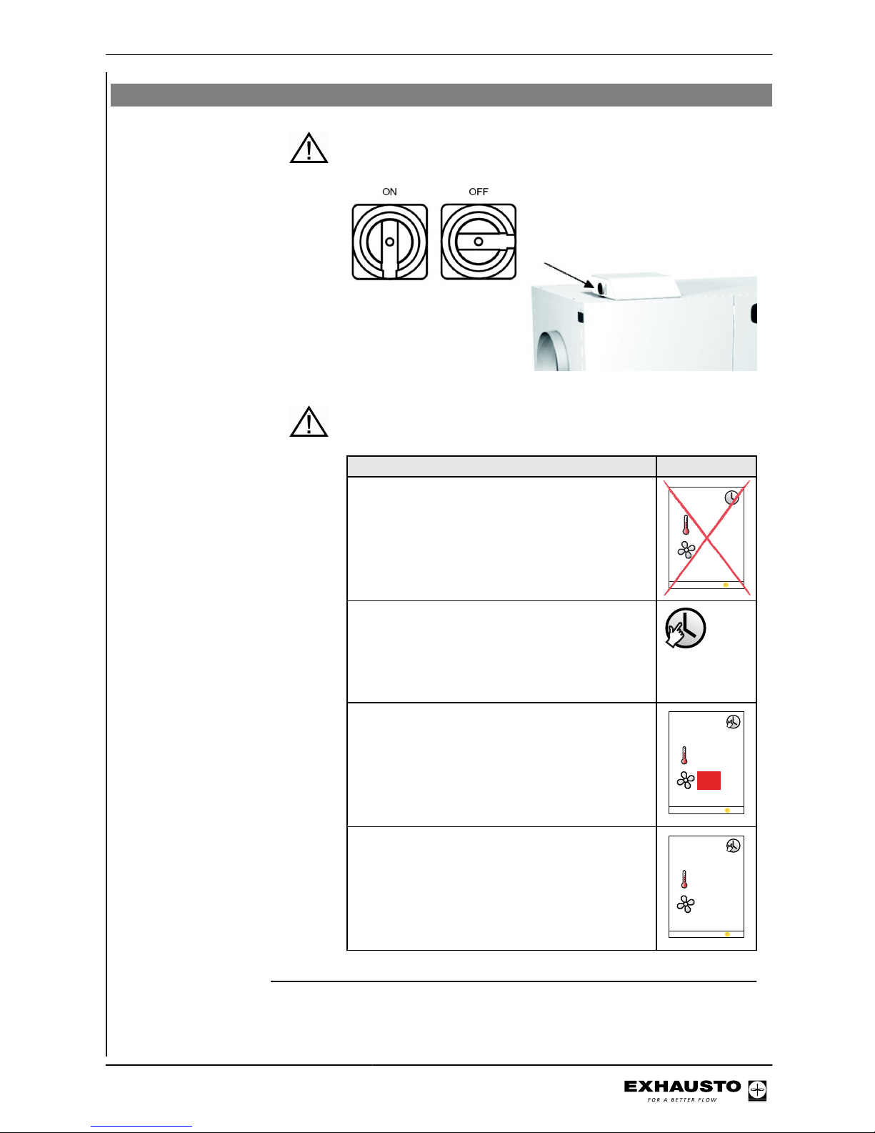
Menu 8 - Service
Do not open the service doors before the supply voltage has been disconnec-
ted at the isolation switch. The isolation switch is positioned on
the left side of the connection box on top of the unit.
Weekly plan It is important to set ventilation to OFF when the weekly plan is
active:
Set ventilation to OFF
NB - If the HMI panel shows 0% (VEX is inactive)
and the unit is operating to a weekly plan when
servicing begins, there is a risk that the program may change via a timer operation and restart the VEX unit.
21
0°C%
29-05-2009 14:32
● Log onto technician menu, using password 1111
● Change to manual operation via menu 1
● Change back to user menu
● The icon for manual operation appears in
the right-hand corner of the menu
● Press the OK button twice
● Use the arrow keys to adjust ventilation to
0%
23 °C
%
29-05-2013 14:32
0
● Press OK
● OFF will now appear on the display next to
the ventilation icon
23 °C
29-05-2013 14:32
OFF
3003246-2014-05-21
Operation
57/100
Page 58
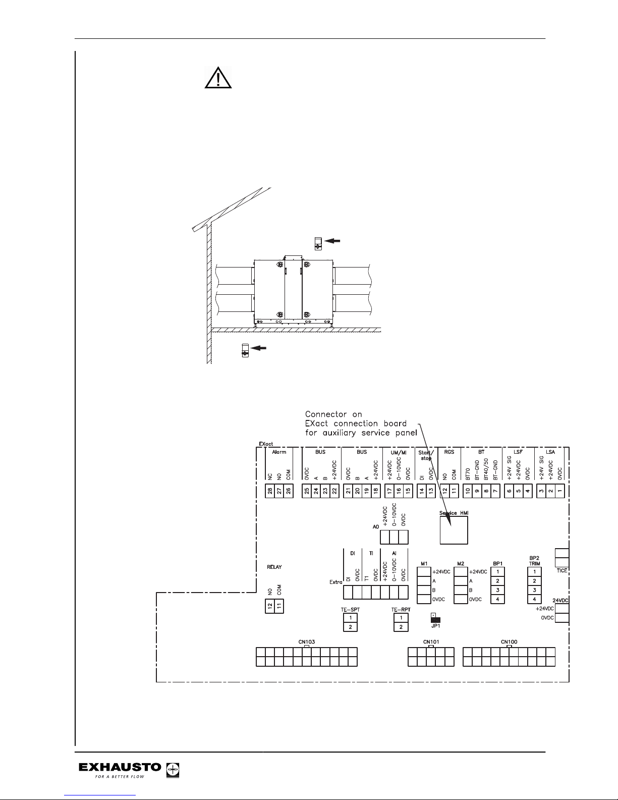
BMS unit or Web
server
If BMS or Web server controls are used, they could override the
OFF function and the VEX may start up irregularly. To disconnect
the BMS or WEB server connection, you must remove the plug
from the connection board. Refer to the section on the terminal
board in the Electrical Installation Guide.
Auxiliary service panel
If the HMI panel is located far from the VEX, it is recommended that an auxiliary HMI
panel be connected to the VEX in the connection box.
RD12627-02
Auxiliary service panel which
overrides the fixed HMI panel
Fixed HMI-panel
Service panel connector - Exact
3003246-2014-05-21
Operation
58/100
Page 59
Menu 8.2 - VDI 6022
Description VDI 6022 is a German hygiene standard.
Menu
8.2 VDI 6022
Filter pressure:
Light >
Extract air filter
Outdoor filter
Off
00Pa
Pa
Light Switch light on/off (applies only to units ordered with lights. The light in the VEX
switches off again when the menu is exited.
Filter monitor Reading for filter pressure loss during operation.
Menu 8.3 - Forced start
Conditions for use To use the forced start menu, the unit must be set to OFF in the user menu (Ven-
tilation).
NB When Menu 8.3 "Forced start" is exited, forced start is reset and normal operation
can be resumed. When a submenu is exited, the values in the submenu are reset.
Menu
8.3 Forced start
Fans >
Recovery >
Heating unit >
Cooling unit
Dampers and relays >
Menu 8.3.1 Fans
8.3.1 Fans
Supply air >
Extract air >
Error on MC1
Error on MC2
0%
0%
No
No
If there are no current faults for the fans ("Fault on MC1 and MC2" shown as "No"),
forced start may be activated for the supply air and extract air fans.
Menu 8.3.2 Recovery
8.3.2 Recovery
Rotor motor
Rotation guard
Error on unit
0%
0
No
If there are no current faults for the rotor motor ("Fault on unit" shown as "No"),
forced start may be activated.
Rotation control
check
If the rotor is not running:
● Turn the rotor one revolution by hand. The value shown for rotation control
should change each time rotation control is activated
3003246-2014-05-21
Operation
59/100
Page 60
Menu 8.3.3 Heating unit
8.3.3 Heating unit
HCE
Supply air
Min. flow
Measured flow
Run on
Error on unit
0%
0%
No
No
0l/s
0l/s
For electric heating coil HCE:
If there are no current faults for the heating coil ("Fault on unit" shown as "No"),
forced start may be activated:
● Start the supply air fan and increase its speed until the measured flow is greater
than the min. flow
● Then start HCE
NB: To avoid the electric heating coil dropping out due to an overheating alarm when
the electric heating coil is stopped:
● Do not exit the menu or stop the supply air fan until Run-on is shown as
"no".
8.3.3 Heating unit
HCW
Error on unit
0%
No
For water heating coil HCW :
If there are no current faults for the heating coil ("Fault on unit" shown as "No"),
forced start may be activated:
● Enter an output level for HCW to start the motor valve and pump for the water
heating coil
Menu 8.3.4 Cooling unit
8.3.4 Køleenhed
CU 0%
Fejl på enhed Nej
(The menu screen is different depending on which cooling unit is selected - CH, CU,
CCW, MXCU)
If there are no current faults for the cooling unit ("Fault on unit" shown as "No"),
forced start may be activated:
● Set the output level for the cooling unit
NB: for CU Only the cooling unit starts. Operating time is limited (until the unit drops out via the
overpressure sensor - automatic reset). There must be a 10-minute interval between starts.
Menu 8.3.5 Dampers and relays
8.3.5 Dampers and relays
LSF >
LSA >
RGS >
Alarm relay >
VDI light >
Off
Off
Off
Off
Off
The following dampers may be forced open or closed via the menu:
● LSF (closing damper, outdoor air)
● LSA (closing damper, exhaust air)
● RGS/AUX OUT (flue gas damper)
● Forced tripping of the alarm relay can be provoked
● The light in units with VDI lighting can be switched on and off
Menu 8.4 - Calibrating MPT
NB The pressure transducers (MPT) may only be calibrated when the unit is stopped.
The doors should be opened to equalise pressure with the surroundings and to
ensure correct calibration.
● Select "Yes" for calibration (automatically changes to "No" again when the
MPTs have been calibrated).
3003246-2014-05-21
Operation
60/100
Page 61
8.4 Calibration of MPT
MPT1, P1 ---
MPT1, P2 --MPT2, P1 --MPT2, P2
MPT3, P1 --MPT3, P2 --MPT4, P1 --MPT4, P2 --MPT5, P1 --MPT5, P2 --Calibrate >
Last calibrated:
Dato 15-06-2009
Tid 10:12:48
---
No
Select "Yes" for calibration (automatically changes to "No" again when the MPTs
have been calibrated).
3003246-2014-05-21
Operation
61/100
Page 62
6. Alarms
6.1 Alarms and info (Menu 4)
NB Alarms are shown in the event of unit faults or irregular operation
● Check the Current list (Menu 4) for alarm messages and refer to the list of
alarms given at the end of these instructions.
List of alarms
Main menu
Settings >
Operating mode >
Operating readings >
Alarm and info >
Time and weekly plan >
Versions >
Safety functions >
Service >
Exit technician menu >
Save settings >
4 Alarm and info
Information
Alarm
Warning
Reset alarms >
Current list >
Alarm log list >
Delete alarm log >
Yes
No
No
No
No
4.5 Current list
Alarm 02
Alarm 01
2009-02-10
2009-02-10
Alarm 03
2009-02-10 18:22:50
Alarm 04 12012
2009-02-10 18:25:00
Alarm 05 13071
2009-02-10 19:00:00
01144
10:54:17
02144
11:01:12
03073
The active alarms can be seen in the current list of alarms in Menu 4.5.
6.2 Reset alarms
Alarm causes must
be found
An alarm can be reset once the cause has been remedied.
Menu 4 All alarms may be reset by selecting reset alarms in Menu 4
More than one alarm If several alarms are active, they will all be reset simultaneously.
Alarms trigger again If an alarm repeatedly triggers, contact a service technician.
6.3 Alarm display – causes of errors
Alarms shown in
display
In the event of unit alarms/warnings, one of the following icons on the right side of
the menu bar is shown – go to current list of alarms to see alarm.
Main menu
Operating mode >
Operating readings >
Main menu
Operating mode >
Operating readings >
Current list
4.5 Current list
Alarm 02
Alarm 01
2009-02-10
2009-02-10
Alarm 03
2009-02-10 18:22:50
Alarm 04 12012
2009-02-10 18:25:00
Alarm 05 13071
2009-02-10 19:00:00
01144
10:54:17
02144
11:01:12
03073
3003246-2014-05-21
Alarms
62/100
Page 63
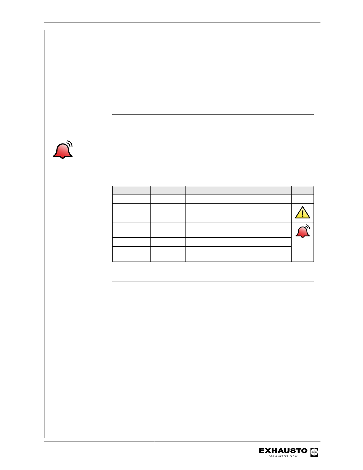
Alarm code If an alarm has been generated, an alarm code is shown in the display in the format
XXYYZ, where .
XX = unit
YY = fault code
Z = category of alarm. See category table in this section.
16 alarms There can be up to 16 alarms on the "Current list". The first alarm to be added to
the queue will be the first alarm to be removed, if there are more than 16 alarms
(FIFO principle).
Info in EXact shown only in the alarm log list Menu 4.6
Example - list of
alarms
360204 is an alarm on EC controller 1 (360204). Alarm description is "The supply
voltage to the EC controller is too low" (36024). The category is critical (360204).
##/nn
XXYYZ
Any active alarm is shown under the alarm symbol. If there is more than one alarm,
each individual alarm is shown for two seconds on a rotation basis.
- ##/nn = alarm no. "##" out of total number "nn" of alarms.
- XXYYZ see definition for alarm number.
Category
Category (Z) Alarm level Effect on operation Icon
1 Info Operation continues
2 Warning Operation continues
3 Alarm Operation continues but with reduced
functionality
4 Critical Operation stops
5 Fire Triggered fire alarm procedure mode
starts
Find troubleshooting directions in the list of alarms via the alarm number.
Alarm log list - Menu
4.6
A letter is shown following the alarm or info code:
C = Clear
S = Set
The alarm log list shows the latest 100 alarms, warnings and past information.
The first alarm/info to be added to the queue will be the first to be removed, if there
are more than 100 of them (FIFO principle).
Delete alarm log The alarm log can be deleted by selecting "Yes". This action cannot be reversed.
3003246-2014-05-21
Alarms
63/100
Page 64
6.4 List of alarms
Main Control VEX
Unit
Fault code
Category
Alarm description
Troubleshooting
(See appendix 1: "Simplified diagrams" for the positioning of dampers, sensors, air directions, etc.)
xx yy z
00 01 1 Control is powered Indicates when control is powered
00 02 1 Unknown reboot of con-
trol
● Unknown fault, call service
00 03 1 A watchdog rebooted
control
● Unknown fault, call service
00 04 1 Software rebooted con-
trol
The software has rebooted the control system.
00 05 1 User rebooted control The user has rebooted the control system.
00 06 1 Power supply voltage
drop rebooted the control system
Reboot of control due to voltage drop
00 16 1 "Manual" alarms reset
by user
The user has reset the alarms
3003246-2014-05-21
Alarms
64/100
Page 65
Frequency converter 1
Unit
Fault code
Category
Alarm description
Troubleshooting
(See appendix 1: "Simplified diagrams" for the positioning of dampers, sensors, air directions, etc.)
xx yy z
01 01 4 One or more phases
between frequency
converter and motor is/
are short-circuited to
earth
● Check the cable between frequency converter 1 and motor
01 02 4 Max. motor current from
frequency converter exceeds limit by 300%
● Check for low voltage to frequency converter 1
01 03 4 Frequency converter
DC circuit max. voltage
exceeds limit
● Check for overvoltage to frequency converter 1
01 04 2 Frequency converter
DC circuit voltage too
low when motor(s)
start(s)
● Check for low voltage to frequency converter 1
01 05 4 Frequency converter
DC circuit voltage too
low when VEX unit
stops
● Check for low voltage to frequency converter 1
01 06 4 Frequency converter
power supply has lost a
phase
● Check wiring from the power supply connection to the isolation
switch in the VEX unit
● Check cable connections from the isolation switch to frequency
converter 1
01 07 4 Frequency converter
power supply to motor(s) has lost a phase
● Check the cable between frequency converter 1 and motor
● Check for a short circuit in the motor windings
01 08 4 Frequency converter
overheated (based on
internal calculations)
● Check if the temperature at frequency converter 1 exceeded the
permitted 35°C when the alarm was tripped. If the temperature
has been too high, the unit will restart when the air temperature
falls below 35°C.
01 10 4 Frequency converter
cooling coil overheated
● Check if the temperature at frequency converter 1 exceeded the
permitted 35°C when the alarm was tripped. If the temperature
has been too high, the unit will restart when the air temperature
falls below 35°C.
01 11 4 Frequency converter
motor(s) drawing too
much current
Fault on frequency converter 1.
01 12 4 Frequency converter
motor 1 overheated
● Check the motor impeller can turn freely
● Check that the fan impeller is not blocked
01 13 4 Frequency converter
motor 2 overheated
● Check the motor impeller can turn freely
● Check that the fan impeller is not blocked
01 14 4 No modbus communi-
cation to frequency converter
● Check the cable between the connection board and frequency
converter 1.
3003246-2014-05-21
Alarms
65/100
Page 66
Frequency converter 1
Unit
Fault code
Category
Alarm description
Troubleshooting
(See appendix 1: "Simplified diagrams" for the positioning of dampers, sensors, air directions, etc.)
xx yy z
01 15 4 Frequency converter
hardware fault
Fault on frequency converter 1.
01 16 4 Frequency converter
software version out of
date
● Upgrade software in frequency converter 1.
3003246-2014-05-21
Alarms
66/100
Page 67
Frequency converter 2
Unit
Fault code
Category
Alarm description
Troubleshooting
(See appendix 1: "Simplified diagrams" for the positioning of dampers, sensors, air directions, etc.)
xx yy z
02 01 4 One or more phases
between frequency
converter and motor is/
are short-circuited to
earth
● Check the cable between frequency converter 2 and motor
02 02 4 Max. motor current from
frequency converter exceeds limit by 300%
● Check for low voltage to frequency converter 2
02 03 4 Frequency converter
DC circuit max. voltage
exceeds limit
● Check for overvoltage to frequency converter 2
02 04 2 Frequency converter
DC circuit voltage too
low when motor(s)
start(s)
● Check for low voltage to frequency converter 2
02 05 4 Frequency converter
DC circuit voltage too
low when VEX unit
stops
● Check for low voltage to frequency converter 2
02 06 4 Frequency converter
power supply has lost a
phase
● Check wiring from the power supply connection to the isolation
switch in the VEX unit
● Check cable connections from the isolation switch to frequency
converter 2
02 07 4 Frequency converter
power supply to motor(s) has lost a phase
● Check the cable between frequency converter 2 and motor
● Check for a short circuit in the motor windings
02 08 4 Frequency converter
overheated (based on
internal calculations)
● Check if the temperature at frequency converter 2 exceeded the
permitted 35°C when the alarm was tripped. If the temperature
has been too high, the unit will restart when the air temperature
falls below 35°C.
02 10 4 Frequency converter
cooling coil overheated
● Check if the temperature at frequency converter 2 exceeded the
permitted 35°C when the alarm was tripped. If the temperature
has been too high, the unit will restart when the air temperature
falls below 35°C.
02 11 4 Frequency converter
motor(s) drawing too
much current
Fault on frequency converter 2.
02 12 4 Frequency converter
motor 1 overheated
● Check the motor impeller can turn freely
● Check that the fan impeller is not blocked
02 13 4 Frequency converter
motor 2 overheated
● Check the motor impeller can turn freely
● Check that the fan impeller is not blocked
02 14 4 No modbus communi-
cation to frequency converter
● Check the cable between the connection board and frequency
converter 2.
3003246-2014-05-21
Alarms
67/100
Page 68
Frequency converter 2
Unit
Fault code
Category
Alarm description
Troubleshooting
(See appendix 1: "Simplified diagrams" for the positioning of dampers, sensors, air directions, etc.)
xx yy z
02 15 4 Frequency converter
hardware fault
Fault on frequency converter 2.
02 16 4 Frequency converter
software version out of
date
● Upgrade software in frequency converter 2.
Rotor control
Unit
Fault code
Category
Alarm description
Troubleshooting
(See appendix 1: "Simplified diagrams" for the positioning of dampers, sensors, air directions, etc.)
xx yy z
03 01 3 Rotation alarm ● Check drive belt is intact. Faulty drive belts must be replaced by
a service technician.
● Check the rotor can rotate easily
● Check for defective rotor guard
03 02 3 Low voltage alarm ● Check for rotor control low voltage at the supply terminals in the
control system box
03 03 3 Overvoltage alarm ● Check for rotor control over voltage at the supply terminals in
the control system box
03 04 3 Rotor motor drawing
too much current
Alarm indicates the step motor (most likely) or rotor control is defective
● Check parts and replace defective part
03 05 3 Rotor control overhea-
ted
Temperature in the rotor control has risen above 95°C
● Replace rotor control
03 06 3 No modbus communi-
cation to rotor control
● Check the cable between the connection board and rotor control
03 07 4 Rotor control inopera-
tive and outdoor air
temperature below 3°C
The VEX has stopped because the outdoor air temperature is below
3°C and the rotor does not operate.
3003246-2014-05-21
Alarms
68/100
Page 69
Pressure transmitter 1
Device
Fault code
Category
Alarm description
Troubleshooting
(See appendix 1: "Simplified diagrams" for the positioning of dampers, sensors, air directions, etc.)
xx yy z
04 01 4 No modbus communi-
cation to pressure
transmitter
● Check the modbus cable between the connection board (EXact)/main board (EXact2) and MPT1.
● Check modbus cable for faults from MPT1 to the other units
04 02 4 Calibration fault ● Re-calibrate
● If the problem continues, MPT1 must be replaced
04 03 1 Calibrate pressure
transmitter
Calibrate MPT1
04 04 1 Pressure transmitter
using old calibration
values
When the unit starts up this information is displayed. It does not necessarily mean that the pressure transmitter has to be calibrated.
● Check if the MPT is out of calibration in Menu 8.4 and recalibrate
if required
04 05 4 Pressure transmitter
not calibrated
● Set the VEX to "OFF" in the user menu and open the doors. Next
calibrate the MPT in Menu 8.4.
Pressure transmitter 2
Device
Fault code
Category
Alarm description
Troubleshooting
(See appendix 1: "Simplified diagrams" for the positioning of dampers, sensors, air directions, etc.)
xx yy z
05 01 4 No modbus communi-
cation to pressure
transmitter
● Check the modbus cable between the connection board (EXact)/main board (EXact2) and MPT2.
● Check modbus cable for faults from MPT2 to the other units
05 02 4 Calibration fault ● Re-calibrate
● If the problem continues, MPT2 must be replaced
05 03 1 Calibrate pressure
transmitter
Calibrate MPT2
05 04 1 Pressure transmitter
using old calibration
values
When the unit starts up this information is displayed. It does not necessarily mean that the pressure transmitter has to be calibrated.
● Check if the MPT is out of calibration in Menu 8.4 and recalibrate
if required
05 05 4 Pressure transmitter
not calibrated
● Set the VEX to "OFF" in the user menu and open the doors. Next
calibrate the MPT in Menu 8.4.
3003246-2014-05-21
Alarms
69/100
Page 70
Pressure transmitter 3
Device
Fault code
Category
Alarm description
Troubleshooting
(See appendix 1: "Simplified diagrams" for the positioning of dampers, sensors, air directions, etc.)
xx yy z
06 01 4 No modbus communi-
cation to pressure
transmitter
● Check the modbus cable between the connection board (EXact)/main board (EXact2) and MPT3.
● Check modbus cable for faults from MPT3 to the other units
06 02 4 Calibration fault ● Re-calibrate
● If the problem continues, MPT3 must be replaced
06 03 1 Calibrate pressure
transmitter
Calibrate MPT3
06 04 1 Pressure transmitter
using old calibration
values
When the unit starts up this information is displayed. It does not necessarily mean that the pressure transmitter has to be calibrated.
● Check if the MPT is out of calibration in Menu 8.4 and recalibrate
if required
06 05 4 Pressure transmitter
not calibrated
● Set the VEX to "OFF" in the user menu and open the doors. Next
calibrate the MPT in Menu 8.4.
Pressure transmitter 4
Unit
Fault code
Category
Alarm description
Troubleshooting
(See appendix 1: "Simplified diagrams" for the positioning of dampers, sensors, air directions, etc.)
xx yy z
07 01 4 No modbus communi-
cation to pressure
transmitter
● Check the cable between the connection board and MPT4
● Check modbus cable for faults from MPT4 to the other units
07 02 4 Calibration fault ● Re-calibrate
● If the problem continues, MPT4 must be replaced
07 03 1 Calibrate pressure
transmitter
Calibrate MPT4
07 04 1 Pressure transmitter
using old calibration
values
When the unit starts up this information is displayed. It does not necessarily mean that the pressure transmitter has to be calibrated.
● Check if the MPT is out of calibration in Menu 8.4 and recalibrate
if required
07 05 4 Pressure transmitter
not calibrated
● Set the VEX to "OFF" in the user menu and open the doors. Next
calibrate the MPT in Menu 8.4.
3003246-2014-05-21
Alarms
70/100
Page 71
Pressure transmitter 5
Device
Fault code
Category
Alarm description
Troubleshooting
(See appendix 1: "Simplified diagrams" for the positioning of dampers, sensors, air directions, etc.)
xx yy z
08 01 4 No modbus communi-
cation to pressure
transmitter
● Check the modbus cable between the connection board (EXact)/main board (EXact2) and MPT5.
● Check modbus cable for faults from MPT5 to the other units
08 02 4 Calibration fault ● Re-calibrate
● If the problem continues, MPT5 must be replaced
08 03 1 Calibrate pressure
transmitter
Calibrate MPT5
08 04 1 Pressure transmitter
using old calibration
values
When the unit starts up this information is displayed. It does not necessarily mean that the pressure transmitter has to be calibrated.
● Check if the MPT is out of calibration in Menu 8.4 and recalibrate
if required
08 05 4 Pressure transmitter
not calibrated
● Set the VEX to "OFF" in the user menu and open the doors. Next
calibrate the MPT in Menu 8.4.
Pressure transmitter 6
Device
Fault code
Category
Alarm description
Troubleshooting
(See appendix 1: "Simplified diagrams" for the positioning of dampers, sensors, air directions, etc.)
xx yy z
09 01 4 No modbus communi-
cation to pressure
transmitter
● Check the modbus cable between the connection board (EXact)/main board (EXact2) and MPT6.
● Check modbus cable for faults from MPT6 to the other units
09 02 4 Calibration fault ● Re-calibrate
● If the problem continues, MPT6 must be replaced
09 03 1 Calibrate pressure
transmitter
Calibrate MPT6
09 04 1 Pressure transmitter
using old calibration
values
When the unit starts up this information is displayed. It does not necessarily mean that the pressure transmitter has to be calibrated.
● Check if the MPT is out of calibration in Menu 8.4 and recalibrate
if required
09 05 4 Pressure transmitter
not calibrated
● Set the VEX to "OFF" in the user menu and open the doors. Next
calibrate the MPT in Menu 8.4.
3003246-2014-05-21
Alarms
71/100
Page 72
Pressure transmitter 7
Unit
Fault code
Category
Alarm description
Troubleshooting
(See appendix 1: "Simplified diagrams" for the positioning of dampers, sensors, air directions, etc.)
xx yy z
10 01 4 No modbus communi-
cation to pressure
transmitter
● Check the cable between the connection board and MPT7
● Check modbus cable for faults from MPT7 to the other units
10 02 4 Calibration fault ● Re-calibrate
● If the problem continues, MPT7 must be replaced
10 03 1 Calibrate pressure
transmitter
Calibrate MPT7
10 04 1 Pressure transmitter
using old calibration
values
When the unit starts up this information is displayed. It does not necessarily mean that the pressure transmitter has to be calibrated.
● Check if the MPT is out of calibration in Menu 8.4 and recalibrate
if required
10 05 4 Pressure transmitter
not calibrated
● Set the VEX to "OFF" in the user menu and open the doors. Next
calibrate the MPT in Menu 8.4.
3003246-2014-05-21
Alarms
72/100
Page 73
Temperature sensor
Unit
Fault code
Category
Alarm description
Troubleshooting
(See appendix 1: "Simplified diagrams" for the positioning of dampers, sensors, air directions, etc.)
xx yy z
11 01 4 TE11:
Extract air duct temperature sensor disconnected
TE11:
● Check the sensor's resistance complies with the actual temperature. See temperature resistance table appendix 2
● If the sensor resistance has significantly changed in value, it
should be replaced.
11 02 4 TE11:
Extract air duct temperature sensor shortcircuited
TE11:
● Check the sensor's resistance complies with the actual temperature. See temperature resistance table appendix 2
● If the sensor resistance has significantly changed in value, it
should be replaced.
11 03 3 TE12:
Exhaust air duct temperature sensor disconnected
TE12:
● Check the sensor's resistance complies with the actual temperature. See temperature resistance table appendix 2
● If the sensor resistance has significantly changed in value, it
should be replaced.
11 04 3 TE12:
Exhaust air duct temperature sensor shortcircuited
TE12:
● Check the sensor's resistance complies with the actual temperature. See temperature resistance table appendix 2
● If the sensor resistance has significantly changed in value, it
should be replaced.
11 05 4 TE21:
Outdoor air duct temperature sensor disconnected
TE21:
● Check the sensor's resistance complies with the actual temperature. See temperature resistance table appendix 2
● If the sensor resistance has significantly changed in value, it
should be replaced.
11 06 4 TE21:
Outdoor air duct temperature sensor shortcircuited
TE21:
● Check the sensor's resistance complies with the actual temperature. See temperature resistance table appendix 2
● If the sensor resistance has significantly changed in value, it
should be replaced.
11 07 4 TE22:
Supply air duct temperature sensor disconnected
TE22:
● Check the sensor's resistance complies with the actual temperature. See temperature resistance table appendix 2.
● If the sensor resistance has significantly changed in value, it
should be replaced.
11 08 4 TE22:
Supply air duct temperature sensor shortcircuited
TE22:
● Check the sensor's resistance complies with the actual temperature. See temperature resistance table appendix 2.
● If the sensor resistance has significantly changed in value, it
should be replaced.
11 09 4 TE-RPT:
Return water pipe temperature sensor on water heating coil disconnected
TE-RPT:
● Check the sensor's resistance complies with the actual temperature. See temperature resistance table appendix 2.
● If the sensor resistance has significantly changed in value, it
should be replaced.
3003246-2014-05-21
Alarms
73/100
Page 74
Temperature sensor
Unit
Fault code
Category
Alarm description
Troubleshooting
(See appendix 1: "Simplified diagrams" for the positioning of dampers, sensors, air directions, etc.)
xx yy z
11 10 4 TE-RPT:
Return water pipe temperature sensor on water heating coil shortcircuited
TE-RPT:
● Check the sensor's resistance complies with the actual temperature. See temperature resistance table appendix 2.
● If the sensor resistance has significantly changed in value, it
should be replaced.
11 11 4 TE-SPT:
Supply water pipe temperature sensor on water cooling coil disconnected
TE-SPT:
● Check the sensor's resistance complies with the actual temperature. See temperature resistance table appendix 2.
● If the sensor resistance has significantly changed in value, it
should be replaced.
11 12 4 TE-SPT:
Supply water pipe temperature sensor on water cooling coil shortcircuited
TE-SPT:
● Check the sensor's resistance complies with the actual temperature. See temperature resistance table appendix 2
● If the sensor resistance has significantly changed in value, it
should be replaced.
11 15 4 Tice
Supply water pipe temperature sensor on water cooling coil disconnected
Tice
● Check the sensor's resistance complies with the actual temperature. See temperature resistance table appendix 2.
● If the sensor resistance has significantly changed in value, it
should be replaced.
11 16 4 Tice
Supply water pipe temperature sensor on water cooling coil shortcircuited
Tice
● Check the sensor's resistance complies with the actual temperature. See temperature resistance table appendix 2.
● If the sensor resistance has significantly changed in value, it
should be replaced.
3003246-2014-05-21
Alarms
74/100
Page 75
Fire thermostats
Device
Fault code
Category
Alarm description
Troubleshooting
(See appendix 1: "Simplified diagrams" for the positioning of dampers, sensors, air directions, etc.)
xx yy z
12 01 5 BT40/50, FIRE:
Triggered fire alarm has
stopped VEX unit
BT40/50, FIRE: In event of Fire: Follow the building emergency procedure
Fire thermostat triggered when there is no fire:
● The closed circuit is broken. Find out why the fire detection unit
has broken the circuit.
● If no unit is connected – check jumper.
12 02 5 BT70, AUX IN:
Triggered fire alarm has
stopped VEX unit
BT70, AUX IN:
In event of Fire: Follow the building emergency procedure
Fire thermostat triggered when there is no fire:
● The closed circuit is broken. Find out why the fire detection unit
has broken the circuit.
● If no unit is connected - check jumper
12 03 3 Fire brigade override
error
The fire brigade override panel has been left in an illegal setting.
Filters
Unit
Fault code
Category
Alarm description
Troubleshooting
(See appendix 1: "Simplified diagrams" for the positioning of dampers, sensors, air directions, etc.)
xx yy z
13 01 2 Replace extract air filter
soon
Replace extract air filter soon
13 02 3 Replace extract air fil-
ter!
Replace extract air filter!
13 03 2 Replace outdoor air fil-
ter soon
Replace outdoor air filter soon
13 04 3 Replace outdoor air fil-
ter soon
Replace outdoor air filter soon
3003246-2014-05-21
Alarms
75/100
Page 76
HC Alarm
Unit
Fault code
Category
Alarm description
Troubleshooting
(See appendix 1: "Simplified diagrams" for the positioning of dampers, sensors, air directions, etc.)
xx yy z
14 01 1 Thermal fuse TSA70
activated
HCE:
Info is reset when the temperature falls below 70℃
14 02 2 Thermal fuse TSA70 is/
has been activated
HCE:
● Check airflow across the electric heating coil, select same fan
speed as when the alarm was triggered
There must be the following min. airflows across the electric heating
coil:
- HCE240: 135l/s
- HCE250: 240l/s
- HCE260: 480l/s
- HCE270: 750l/s
- HCE280: 1,260l/s
14 03 1 Thermal fuse TSA120
activated
HCE:
Info is reset when the temperature falls below 120℃.
14 04 4 Thermal fuse TSA120
is/has been activated
HCE:
● Check airflow across the electric heating coil, select same fan
speed as when the alarm was triggered
There must be the following min. airflows across the electric heating
coil:
- HCE240: 135l/s
- HCE250: 240l/s
- HCE260: 480l/s
- HCE270: 750l/s
- HCE280: 1,260l/s
NB: The electric heating coil must be manually reset before the
alarm can be reset in the control panel.
14 07 1 Electrical heating coil
internal thermal fuse
activated
HCE:
Info is reset when the temperature falls below 60°C in the control
system box
14 08 4 Electrical heating coil
control's internal thermal fuse is/has been
activated
HCE:
● Temperature in the electrical heating coil's control system box
is/has been greater than 60℃. Check for possible causes for this
high temperature and rectify the fault.
14 09 3 Return water temp. be-
coming too low. VEX
running in reduced
mode and frost protection
HCW:
● Check that the hot water supply to the heating coil is functioning
If the hot water supply is functioning, check if the motor valve opens
and the circulation pump is running.
● Check by turning the unit to "OFF" in the user menu and force
start the motor valve and circulation pump in specialist menu 8.3
The alarm resets automatically when the temperature rises above
the constant temperature level
3003246-2014-05-21
Alarms
76/100
Page 77
HC Alarm
Unit
Fault code
Category
Alarm description
Troubleshooting
(See appendix 1: "Simplified diagrams" for the positioning of dampers, sensors, air directions, etc.)
xx yy z
14 10 3 Return water temp. too
low. Frost protection activated. VEX temporarily stopped
HCW:
● Check that the hot water supply to the heating coil is functioning
If the hot water supply is functioning, check if the motor valve opens
and the circulation pump is running.
● Check by turning the unit to "OFF" in the user menu and force
start the motor valve and circulation pump in specialist menu 8.3
The alarm resets automatically when the temperature rises above
the constant temperature level
14 11 3 Return water temp.
measured by external
sensor becoming too
low. VEX running in reduced mode
HCW:
● Check that the hot water supply to the heating coil is functioning
If the hot water supply is functioning, check if the motor valve opens
and the circulation pump is running.
● Check by turning the unit to "OFF" in the user menu and force
start the motor valve and circulation pump in specialist menu 8.3
The alarm resets automatically when the temperature rises above
the constant temperature level
14 12 3 Return water temp.
measured by external
sensor becoming too
low. VEX temporarily
stopped.
HCW:
● Check that the hot water supply to the heating coil is functioning
If the hot water supply is functioning, check if the motor valve opens
and the circulation pump is running.
● Check by turning the unit to "OFF" in the user menu and force
start the motor valve and circulation pump in specialist menu 8.3
The alarm resets automatically when the temperature rises above
the constant temperature level
14 13 4 Max. total no. of restarts
within one hour reached
HCW:
● Check that the hot water supply to the heating coil is functioning
If the hot water supply is functioning, check if the motor valve opens
and the circulation pump is running.
● Check by turning the unit to "OFF" in the user menu and force
start the motor valve and circulation pump in specialist menu 8.3
The alarm resets automatically when the temperature rises above
the constant temperature level
14 14 4 Could not increase re-
turn water temp. within
five minutes after frost
protection with VEX
stopped
HCW:
● Check that the hot water supply to the heating coil is functioning
If the hot water supply is functioning, check if the motor valve opens
and the circulation pump is running.
● Check by turning the unit to "OFF" in the user menu and force
start the motor valve and circulation pump in specialist menu 8.3
The alarm resets automatically when the temperature rises above
the constant temperature level
3003246-2014-05-21
Alarms
77/100
Page 78
HC Sensor
Unit
Fault code
Category
Alarm description
Troubleshooting
(See appendix 1: "Simplified diagrams" for the positioning of dampers, sensors, air directions, etc.)
xx yy z
15 01 4 Supply air duct temper-
ature sensor disconnected
● Check the sensor's resistance complies with the actual temperature. See temperature resistance table appendix 2
● If the sensor resistance has significantly changed in value, it
should be replaced.
15 02 4 Supply air duct temper-
ature sensor shortcircuited
● Check the sensor's resistance complies with the actual temperature. See temperature resistance table appendix 2
● If the sensor resistance has significantly changed in value, it
should be replaced.
15 05 4 Supply water pipe tem-
perature sensor on water cooling coil disconnected
● Check the sensor's resistance complies with the actual temperature. See temperature resistance table appendix 2
● If the sensor resistance has significantly changed in value, it
should be replaced.
15 06 4 Supply water pipe tem-
perature sensor on water cooling coil shortcircuited
● Check the sensor's resistance complies with the actual temperature. See temperature resistance table appendix 2
● If the sensor resistance has significantly changed in value, it
should be replaced.
15 07 4 Return water pipe tem-
perature sensor on water heating coil disconnected
● Check the sensor's resistance complies with the actual temperature. See temperature resistance table appendix 2
● If the sensor resistance has significantly changed in value, it
should be replaced.
15 08 4 Return water pipe tem-
perature sensor on water heating coil shortcircuited
● Check the sensor's resistance complies with the actual temperature. See temperature resistance table appendix 2
● If the sensor resistance has significantly changed in value, it
should be replaced.
15 09 4 Return water pipe ex-
ternal temperature sensor on water heating
coil disconnected
● Check the sensor's resistance complies with the actual temperature. See temperature resistance table appendix 2
● If the sensor resistance has significantly changed in value, it
should be replaced.
15 10 4 Return water pipe ex-
ternal temperature sensor on water heating
coil is short-circuited
● Check the sensor's resistance complies with the actual temperature. See temperature resistance table appendix 2
● If the sensor resistance has significantly changed in value, it
should be replaced.
15 13 4 Heat control internal
temperature sensor disconnected
● Replace the heat control circuit board MHCW
15 14 4 Heat control internal
temperature sensor
short-circuited
● Replace the heat control circuit board MHCW
3003246-2014-05-21
Alarms
78/100
Page 79
HC Controller
Device
Fault code
Category
Alarm description
Troubleshooting
(See appendix 1: "Simplified diagrams" for the positioning of dampers, sensors, air directions, etc.)
xx yy z
16 01 1 MHCW: Module config-
ured incorrectly. Check
CN6 on PCB
Check the jumper in the CN6 connector on the heat control circuit
board
MHCW: - there must be a jumper across 7 and 8
MHCE: - a jumper must not be fitted
16 02 1 HCW: Fan speed tem-
porarily reduced
HCW: Fan speed temporarily reduced because warning limit for frost
protection of water heating coil has been reached
16 03 1 HCW: VEX temporarily
stopped
HCW: Fan speed temporarily reduced because stop temperature for
frost protection of water heating coil has been reached
16 04 1 HCW: VEX stopped HCW: Fan speed stopped because of frost alarm on the water heat-
ing coil
16 05 1 HCE: Run-on operating
because electric heating coil warm in last
three minutes
HCE: The fans run on for three minutes after the electric heating coil
has been in operation
16 06 1 HC: Heat control cur-
rently run locally due to
service
HC: Heat control temporarily controlled by Lodam Multi Tool. Override lasts for max. 60 minutes
16 07 1 HC: Heat control safety
functions overridden locally due to service
HC: Heat control temporarily controlled by Lodam Multi Tool. Override lasts for max. 60 minutes
16 13 4 HC: Heat control detec-
ted but not selected in
VEX configuration
HC: The heating coil is configured in menu 3.4 "Accessories".
16 14 4 MHC: Heat control con-
figured incorrectly in
connection with selected VEX configuration
Check the jumper in the CN6 connector on the heat control circuit
board
MHCW: - there must be a jumper across 7 and 8
MHCE: - a jumper must not be fitted
16 15 4 MHCW: No modbus
communication to water
heat control
MHCW:
● Check the modbus cable between the connection board (EXact)/main board (EXact2) and MHCW.
● Check modbus cable for faults from HCW to the other units.
16 16 3 MHCE: No modbus
communication to electrical heating control
MHCE:
● Check the modbus cable between the connection board (EXact)/main board (EXact2) and MHCE.
● Check modbus cable for faults from HCE to the other units
3003246-2014-05-21
Alarms
79/100
Page 80
Airflow/pressure
Unit
Fault code
Category
Alarm description
Troubleshooting
(See appendix 1: "Simplified diagrams" for the positioning of dampers, sensors, air directions, etc.)
xx yy z
20 01 1 Airflow/pressure in ex-
tract air duct airflow too
high
The unit provides airflow that is 25% below the set point
● Check the fan speed settings in indoor air quality level and the
fan limits
20 02 2 Airflow/pressure in ex-
tract air duct airflow too
high for last five minutes
The unit provides airflow that is 25% below the set point for more
than five minutes
● Check the fan speed settings in indoor air quality level and the
fan limits
20 03 1 Airflow/pressure in ex-
tract air duct airflow too
low
The unit provides airflow/pressure that is 25 % below the set point
● Check the fan speed settings in indoor air quality level and the
fan limits
20 04 2 Airflow/pressure in ex-
tract air duct airflow too
low for last five minutes
The unit has provided airflow/pressure that is 25 % below the set
point for more than 5 minutes
● Check the fan speed settings in indoor air quality level and the
fan limits
20 05 1 Airflow/pressure in sup-
ply air duct airflow too
high
The unit provides airflow that is 25% below the set point
● Check the fan speed settings in indoor air quality level and the
fan limits
20 06 2 Airflow/pressure in sup-
ply air duct airflow too
high for last five minutes
The unit provides airflow that is 25% below the set point for more
than five minutes
● Check the fan speed settings in indoor air quality level and the
fan limits
20 07 1 Airflow/pressure in sup-
ply air duct airflow too
low
The unit provides airflow/pressure that is 25 % below the set point
● Check the fan speed settings in indoor air quality level and the
fan limits
20 08 2 Airflow/pressure in sup-
ply air duct airflow too
low for last five minutes
The unit has provided airflow/pressure that is 25 % below the set
point for more than 5 minutes
● Check the fan speed settings in indoor air quality level and the
fan limits
20 09 1 Minimum supply air
duct airflow for cooling/
warming not achieved
The required supply airflow for operating cooling/heating units was
not achieved
● Check the fan speed settings in indoor air quality level and the
fan limits
20 10 3 Minimum supply air
duct airflow for cooling/
warming not achieved
in last five minutes
The required supply airflow for operating cooling/heating units was
not achieved within five minutes
● Check the fan speed settings in indoor air quality level and the
fan limits
20 11 1 Cooling cannot be re-
leased because supply
and extract airflow ratio
not achieved
The required air balance between supply air and extract air is higher
than the permitted limits of 1, 15:1
● Check the fan speed settings in indoor air quality level and the
fan limits
20 12 3 Cooling cannot be re-
leased because supply
and extract airflow ratio
not achieved in last five
minutes
The required air balance between supply air and extract air is still
higher than the permitted limits of 1, 15:1 after five minutes.
● Check the fan speed settings in indoor air quality level and the
fan limits
3003246-2014-05-21
Alarms
80/100
Page 81
CO2 sensor
Device
Fault code
Category
Alarm description
Troubleshooting
(See appendix 1: "Simplified diagrams" for the positioning of dampers, sensors, air directions, etc.)
xx yy z
21 01 2 No modbus communi-
cation to MIO CO2 module
● Check the modbus cable between the connection board (EXact)/main board (EXact2) and MIO module.
● Check the modbus cable from the MIO module to the other units
for faulty wiring.
● Check the DIP-switch settings in the MIO module, refer to MIO
module instructions.
21 02 2 CO2 level below 100
ppm. CO2 sensor may
be defective.
● CO2 sensor may be defective and should be replaced.
21 03 2 CO2 input via BMS se-
lected and BMS has not
been configured.
● Configure BMS.
Temperature sensor MIO-TS
Device
Fault code
Category
Alarm description
Troubleshooting
(See appendix 1: "Simplified diagrams" for the positioning of dampers, sensors, air directions, etc.)
xx yy z
22 01 2 No modbus communi-
cation to MIO-TS module
● Check the modbus cable between the connection board (EXact)/main board (EXact2) and MIO module.
● Check the modbus cable from the MIO module to the other units
for faulty wiring.
● Check the DIP-switch settings in the MIO module, refer to MIO
module instructions.
22 02 2 Temperature sensor
disconnected
● Check the sensor's resistance complies with the actual temperature. See temperature resistance table appendix 2.
● If the sensor resistance has significantly changed in value, it
should be replaced.
22 03 2 Temperature sensor
short-circuited
● Check the sensor's resistance complies with the actual temperature. See temperature resistance table appendix 2.
● If the sensor resistance has significantly changed in value, it
should be replaced.
3003246-2014-05-21
Alarms
81/100
Page 82
Humidity sensor RH
Device
Fault code
Category
Alarm description
Troubleshooting
(See appendix 1: "Simplified diagrams" for the positioning of dampers, sensors, air directions, etc.)
xx yy z
23 01 2 No modbus communi-
cation to MIO-RH module
● Check the modbus cable between the connection board (EXact)/main board (EXact2) and MIO module.
● Check the modbus cable from the MIO module to the other units
for faulty wiring.
● Check the DIP-switch settings in the MIO module, refer to MIO
module instructions.
23 02 2 Humidity level is below
2% – RH sensor may be
defective
● Humidity sensor may be defective and should be replaced
23 03 2 RH input via BMS se-
lected and BMS has not
been configured.
● Configure BMS.
Motion sensor PIR
Unit
Fault code
Category
Alarm description
Troubleshooting
(See appendix 1: "Simplified diagrams" for the positioning of dampers, sensors, air directions, etc.)
xx yy z
24 01 2 No modbus communi-
cation to PIR module
● Check the modbus cable between the connection board (EXact)/main board (EXact2) and PIR module.
● Check the modbus cable from the MCCW module to the other
units for faulty wiring.
● Check the DIP-switch settings in the PIR module, refer to MIO
module instructions or PIRB-AS instructions.
24 02 2 PIR input via BMS se-
lected and BMS has not
been configured.
● Configure BMS.
3003246-2014-05-21
Alarms
82/100
Page 83
Cooling unit
Unit
Fault code
Category
Alarm description
Troubleshooting
(See appendix 1: "Simplified diagrams" for the positioning of dampers, sensors, air directions, etc.)
xx yy z
25 01 3 Cooling unit stopped
because of low evaporator pressure
● Check the low-pressure switch. The low-pressure switch cuts
out at 0.69 bar and re-engages at 2.21 bar. The unit must cut
out at the low-pressure switch and this can be checked by comparing it with the actual manometer pressure
● Check VEX regulating valve function.
● Check volume of the unit. The required amount is shown on the
information plate.
25 02 3 Cooling unit stopped
because of high evaporator pressure
● Check the high-pressure switch. The high-pressure switch cuts
out at 29.3 bar. The unit must cut out at the high-pressure switch
and this can be checked by comparing it with the actual manometer pressure
● Check VEX regulating valve function.
● Check volume of the unit. The required amount is shown on the
information plate.
25 03 3 Cooling unit stopped
because of overeating
in cooling compressor
● Check the compressor power consumption
● Check airflow across the cooling unit, select same fan speed as
when the alarm was triggered. There must be the following min.
airflows across the cooling unit:
- CU240: 195l/s
- CU250: 417l/s
- CU260: 528l/s
- CU270: 611l/s
● Check VEX regulating valve function.
● Check volume of the unit.
25 04 3 Cooling unit stopped
because of high compressed gas temperature
● Check the VEX airflow measurement, which controls the airflow
through the condenser coil, is correct
● Check airflow across the cooling unit, select same fan speed as
when the alarm was triggered. There must be the following min.
airflows across the cooling unit:
- CU240: 195l/s
- CU250: 417l/s
- CU260: 528l/s
- CU270: 611l/s
● Check volume of the unit.
25 05 3 Supply air duct temper-
ature sensor disconnected
● Check the sensor's resistance complies with the actual temperature. See temperature resistance table appendix 2.
● If the sensor resistance has significantly changed in value, it
should be replaced.
25 06 3 Supply air duct temper-
ature sensor shortcircuited
● Check the sensor's resistance complies with the actual temperature. See temperature resistance table appendix 2.
● If the sensor resistance has significantly changed in value, it
should be replaced.
25 07 3 Outdoor air duct tem-
perature sensor disconnected
● Check the sensor's resistance complies with the actual temperature. See temperature resistance table appendix 2.
● If the sensor resistance has significantly changed in value, it
should be replaced.
3003246-2014-05-21
Alarms
83/100
Page 84
Cooling unit
Unit
Fault code
Category
Alarm description
Troubleshooting
(See appendix 1: "Simplified diagrams" for the positioning of dampers, sensors, air directions, etc.)
xx yy z
25 08 3 Outdoor air duct tem-
perature sensor shortcircuited
● Check the sensor's resistance complies with the actual temperature. See temperature resistance table appendix 2.
● If the sensor resistance has significantly changed in value, it
should be replaced.
25 15 3 Cooling control detec-
ted but not selected in
VEX configuration
The cooling unit is configured in Menu 3.3 VEX configuration
25 16 3 No modbus communi-
cation to cooling control
● Check the modbus cable between the connection board and the
MCUC module.
● Check the modbus cable from the MCUC module to the other
units for faulty wiring
External cooling unit (MXCU) sensor
Unit
Fault code
Category
Alarm description
Troubleshooting
(See appendix 1: "Simplified diagrams" for the positioning of dampers, sensors, air directions, etc.)
xx yy z
27 01 4 Supply air duct temper-
ature sensor disconnected
● Check the sensor's resistance complies with the actual temperature. See temperature resistance table appendix 2.
● If the sensor resistance has significantly changed in value, it
should be replaced.
27 02 4 Supply air duct temper-
ature sensor shortcircuited
● Check the sensor's resistance complies with the actual temperature. See temperature resistance table appendix 2.
● If the sensor resistance has significantly changed in value, it
should be replaced.
3003246-2014-05-21
Alarms
84/100
Page 85
External cooling unit (MXCU) control
Unit
Fault code
Category
Alarm description
Troubleshooting
(See appendix 1: "Simplified diagrams" for the positioning of dampers, sensors, air directions, etc.)
xx yy z
28 01 1 Module configured in-
correctly. Check CN6
on PCB
● Check the jumper in the CN6 connector on the cooling control
circuit board. There must be a jumper across 4 and 6, and
across 5 and 6.
28 06 1 Cooling control current-
ly run locally due to
service
Cooling control temporarily controlled by Lodam Multi Tool. Override
lasts for max. 60 minutes
28 07 1 Cooling control safety
functions overridden locally due to service
Cooling control temporarily controlled by Lodam Multi Tool. Override
lasts for max. 60 minutes
28 13 4 Cooling control detec-
ted but not selected in
VEX configuration
The cooling unit is configured in menu 3.4 "Accessories".
28 14 4 Cooling control config-
ured incorrectly in connection with selected
VEX configuration
● Check the jumper in the CN6 connector on the cooling control
circuit board. There must be a jumper across 4 and 6, and
across 5 and 6.
28 15 4 No modbus communi-
cation to cooling control
● Check the modbus cable between the connection board (EXact)/main board (EXact2) and MXCU module.
● Check the modbus cable from the MXCU module to the other
units for faulty wiring.
MCCW
Unit
Fault code
Category
Alarm description
Troubleshooting
(See appendix 1: "Simplified diagrams" for the positioning of dampers, sensors, air directions, etc.)
xx yy z
30 01 4 Supply air duct temper-
ature sensor disconnected
● Check the sensor's resistance complies with the actual temperature. See temperature resistance table appendix 2.
● If the sensor resistance has significantly changed in value, it
should be replaced.
30 02 4 Supply air duct temper-
ature sensor shortcircuited
● Check the sensor's resistance complies with the actual temperature. See temperature resistance table appendix 2.
● If the sensor resistance has significantly changed in value, it
should be replaced.
30 05 4 Supply water pipe tem-
perature sensor on water cooling coil disconnected
● Check the sensor's resistance complies with the actual temperature. See temperature resistance table appendix 2.
● If the sensor resistance has significantly changed in value, it
should be replaced.
30 06 4 Supply water pipe tem-
perature sensor on water cooling coil shortcircuited
● Check the sensor's resistance complies with the actual temperature. See temperature resistance table appendix 2.
● If the sensor resistance has significantly changed in value, it
should be replaced.
3003246-2014-05-21
Alarms
85/100
Page 86
MCCW control
Unit
Fault code
Category
Alarm description
Troubleshooting
(See appendix 1: "Simplified diagrams" for the positioning of dampers, sensors, air directions, etc.)
xx yy z
31 01 1 Module configured in-
correctly. Check CN6
on PCB
● Check the jumper in the CN6 connector on the cooling control
circuit board. There must be a jumper across 4 and 6, and
across 5 and 6.
31 06 1 Cooling control current-
ly run locally due to
service
Cooling control temporarily controlled by Lodam Multi Tool. Override
lasts for max. 60 minutes
31 07 1 Cooling control safety
functions overridden locally due to service
Cooling control temporarily controlled by Lodam Multi Tool. Override
lasts for max. 60 minutes
31 13 4 Cooling control detec-
ted but not selected in
VEX configuration
The cooling unit is configured in menu 3.4 "Accessories".
31 14 4 Cooling control config-
ured incorrectly in connection with selected
VEX configuration
● Check the jumper in the CN6 connector on the cooling control
circuit board. There must be a jumper across 4 and 6, and
across 5 and 6.
31 15 4 No modbus communi-
cation to cooling control
● Check the modbus cable between the connection board and the
MCCW module
● Check the modbus cable from the MCCW module to the other
units for faulty wiring
Modbus Status
Unit
Fault code
Category
Alarm description
Troubleshooting
(See appendix 1: "Simplified diagrams" for the positioning of dampers, sensors, air directions, etc.)
xx yy z
34 01 1 SendModbusDataRe-
ceive fail
Contact EXHAUSTO A/S
34 02 1 SendModbusDataSend
fail
Contact EXHAUSTO A/S
34 03 1 SendModbusDataCon-
nect fail
Contact EXHAUSTO A/S
34 04 1 SetRegister Connect
fail
Contact EXHAUSTO A/S
34 05 1 SetCoil Connect fail Contact EXHAUSTO A/S
34 06 1 GetRegister Connect
fail
Contact EXHAUSTO A/S
3003246-2014-05-21
Alarms
86/100
Page 87
External control
Unit
Fault code
Category
Alarm description
Troubleshooting
(See appendix 1: "Simplified diagrams" for the positioning of dampers, sensors, air directions, etc.)
xx yy z
35 01 3 No modbus communi-
cation to the MIO-AUX1
(extract air) module
● Check the modbus cable between the connection board (EXact)/main board (EXact2) and MIO module.
● Check the modbus cable from the MIO module to the other units
for faulty wiring.
● Check the DIP-switch settings in the MIO module, refer to MIO
module instructions.
35 02 3 No modbus communi-
cation to the MIO-AUX2
(supply air) module
● Check the modbus cable between the connection board (EXact)/main board (EXact2) and MIO module.
● Check the modbus cable from the MIO module to the other units
for faulty wiring.
● Check the DIP-switch settings in the MIO module, refer to MIO
module instructions.
VEX configuration
Unit
Fault code
Category
Alarm description
Troubleshooting
(See appendix 1: "Simplified diagrams" for the positioning of dampers, sensors, air directions, etc.)
xx yy z
40 01 4 VEX type has not been
configured
● Configure the VEX in menu 3.3
40 02 4 VEX size has not been
configured
● Configure VEX size in menu 3.3
40 03 4 VEX orientation has not
been configured
● Configure orientation in menu 3.3
Dining solution
Unit
Fault code
Category
Alarm description
Troubleshooting
(See appendix 1: "Simplified diagrams" for the positioning of dampers, sensors, air directions, etc.)
xx yy z
42 01 4 Motor control 1 does not
fit Dining Solution
● Control of external extract air fan, which replaces internal extract
air fan
3003246-2014-05-21
Alarms
87/100
Page 88
Modbus Status
Device
Fault code
Category
Alarm description
Troubleshooting
(See appendix 1: "Simplified diagrams" for the positioning of dampers, sensors, air directions, etc.)
xx yy z
43 01 4 Temperature sensor af-
ter the CCW surface in
the supply air duct is
short-circuited.
● Check the sensor's resistance complies with the actual temperature. See temperature resistance table appendix 2.
● If the sensor resistance has significantly changed in value, it
should be replaced.
43 02 4 Temperature sensor af-
ter the CCW surface in
the supply air duct is
open-circuit.
● Check the sensor's resistance complies with the actual temperature. See temperature resistance table appendix 2.
● If the sensor resistance has significantly changed in value, it
should be replaced.
43 03 4 The temperature sen-
sor in the supply to the
CCW surface in the extract air duct is shortcircuited.
● Check the sensor's resistance complies with the actual temperature. See temperature resistance table appendix 2.
● If the sensor resistance has significantly changed in value, it
should be replaced.
43 04 4 The temperature sen-
sor in the supply to the
CCW surface in the extract air duct is open-circuit.
● Check the sensor's resistance complies with the actual temperature. See temperature resistance table appendix 2.
● If the sensor resistance has significantly changed in value, it
should be replaced.
43 05 4 Pressure gas tempera-
ture sensor has been
short-circuited.
● Check the sensor's resistance complies with the actual temperature. See temperature resistance table appendix 2.
● If the sensor resistance has significantly changed in value, it
should be replaced.
43 06 4 Pressure gas tempera-
ture sensor has interrupted.
● Check the sensor's resistance complies with the actual temperature. See temperature resistance table appendix 2.
● If the sensor resistance has significantly changed in value, it
should be replaced.
43 07 4 Suction gas pressure
sensor has been shortcircuited.
● Check connection between sensor and cooling/heat pump control system.
● Contact EXHAUSTO service.
43 08 4 Suction gas pressure
sensor has interrupted.
● Check connection between sensor and cooling/heat pump control system.
● Contact EXHAUSTO service.
43 09 4 Pressure gas pressure
sensor has been shortcircuited.
● Check connection between sensor and cooling/heat pump control system.
● Contact EXHAUSTO service.
43 10 4 Pressure gas pressure
sensor has interrupted.
● Check connection between sensor and cooling/heat pump control system.
● Contact EXHAUSTO service.
43 11 4 Low pressure guard
has triggered a stop.
Call a cooling technician.
43 12 4 High pressure guard
has triggered a stop.
Call a cooling technician.
Three operational stops due to high pressure are permitted before
this alarm is triggered.
3003246-2014-05-21
Alarms
88/100
Page 89
Modbus Status
Device
Fault code
Category
Alarm description
Troubleshooting
(See appendix 1: "Simplified diagrams" for the positioning of dampers, sensors, air directions, etc.)
xx yy z
43 13 4 High pressure gas tem-
perature has triggered a
stop.
Call a cooling technician.
43 14 4 MC alarm output activa-
ted.
Read any error code on the motor controller display and contact
service.
This alarm cannot be cancelled via the HMI panel until it has been
cancelled on the cooling/heat pump motor controller:
● Turn off the power to the cooling/heat pump for one minute at
the isolation switch on the cooling/heat pump.
● Then cancel the alarm via the HMI panel.
43 15 4 Unknown configuration. Chiller size has not been configured. Contact EXHAUSTO service.
CH Status
Device
Fault code
Category
Alarm description
Troubleshooting
(See appendix 1: "Simplified diagrams" for the positioning of dampers, sensors, air directions, etc.)
xx yy z
44 02 2 Suction pressure is low. The unit is running in reduced mode.
44 03 2 Pressure gas pressure
is high.
The unit is running in reduced mode.
44 10 2 Reduced due to low
supply temperature.
Cooling/heat pump unit is running in reduced mode due to low supply
temperature to the coil in the exhaust duct.
● Check that the frost protection level is correctly set for the glycol
mixture.
● Increase the air flow.
44 11 2 Stopped due to low sup-
ply temperature.
Cooling/heat pump unit has stopped due to low supply temperature
to the coil in the exhaust duct.
● Check that the frost protection level is correctly set for the glycol
mixture.
● Increase the air flow.
44 12 3 Stopped due to icing of
exhaust coil.
Cold water coil in the exhaust has iced up.
● Thaw ice by force-starting the extract air fan for a short period.
44 15 4 Cooling/heat pump has
not been correctly configured.
A cooling/heating pump unit has been found, but the unit is not selected in the "Accessories" menu.
44 16 4 Cooling/heating pump
communications error.
Communication to the cooling/heating pump unit has been interrupted.
1. Check the unit's supply voltage.
2. Check the modbus connection between the EXact control system
and the cooling/heat pump unit.
3003246-2014-05-21
Alarms
89/100
Page 90
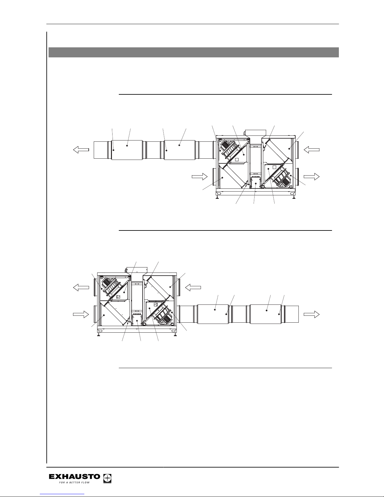
Appendix 1 - Simplified diagrams
Simplified diagrams
Simplified diagrams for unit with chiller
For units with an installed chiller, see the simplified diagrams at the rear of the chiller
instructions.
VEX240-250-260-270L fan placement 1
HCCCW
MC1
MC2RHX2M
2,2,A
Supply air
2,1,A
Outdoor air
1,1,A
Extract air
1,2,A
Exhaust air
RD12908GB-02
T-heatT-Cool
TE12
TE21
TE11
TE22 MPT2
MPT1
VEX240-250-260-270L fan placement 1
HC CCW
MC1
MC2RHX2M
2,2,A
Supply air
2,1,A
Outdoor air
1,1,A
Extract air
1,2,A
Exhaust air
RD12909GB-02
TE11
TE12
TE21
TE22
MPT1
MPT2
T-heat
T-Cool
3003246-2014-05-21
Appendix 1 - Simplified diagrams
90/100
Page 91
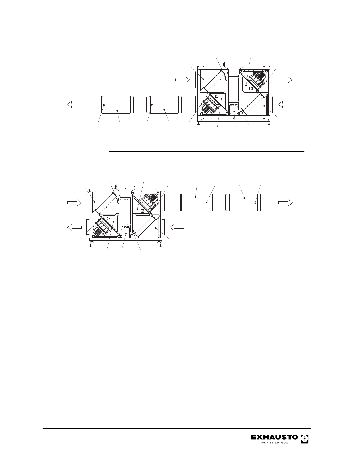
VEX240-250-260-270L fan placement 2
HCCCW
MC2
MC1 RHX2M
2,2,A
Supply air
2,1,A
Outdoor air
1,1,A
Extract air
1,2,A
Exhaust air
RD12910GB-02
TE11 TE12
TE21
TE22
MPT2
MPT1
T-heatT-Cool
VEX240-250-260-270L fan placement 2
HC CCW
MC2
MC1 RHX2M
2,2,A
Supply air
2,1,A
Outdoor air
1,1,A
Extract air
1,2,A
Exhaust air
RD12911GB-02
TE11
TE12
TE21
TE22
MPT1
MPT2
T-heat
T-Cool
3003246-2014-05-21
Appendix 1 - Simplified diagrams
91/100
Page 92
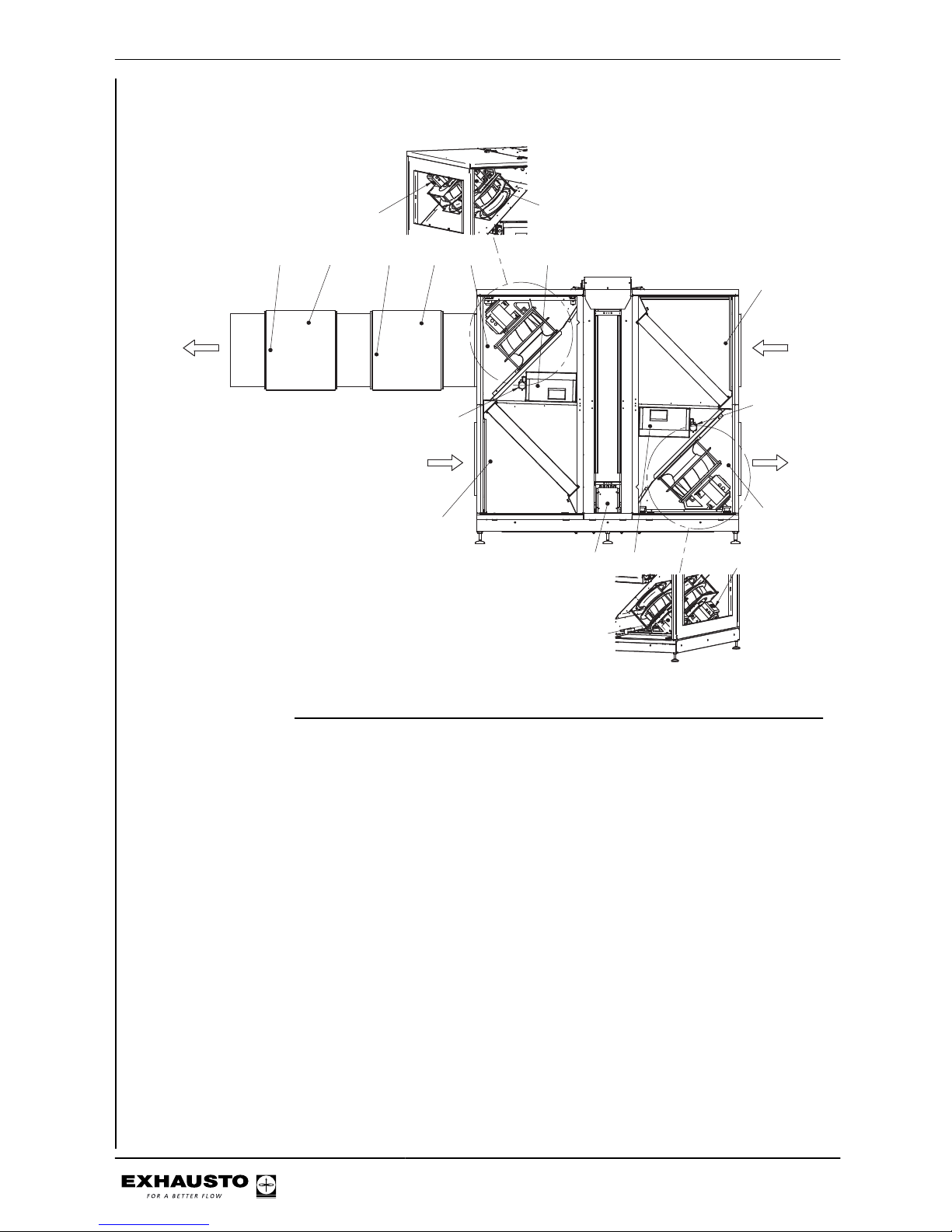
VEX280L fan placement 1
HCCCW MC1
MC2RHX2M
2,2,A
Supply air
2,1,A
Outdoor air
1,1,A
Extract air
1,2,A
Exhaust air
TE12
TE21
TE11
TE22
MPT1
MPT2
M1
M2
M2
M1
RD12920GB-02
T-heat
T-Cool
3003246-2014-05-21
Appendix 1 - Simplified diagrams
92/100
Page 93
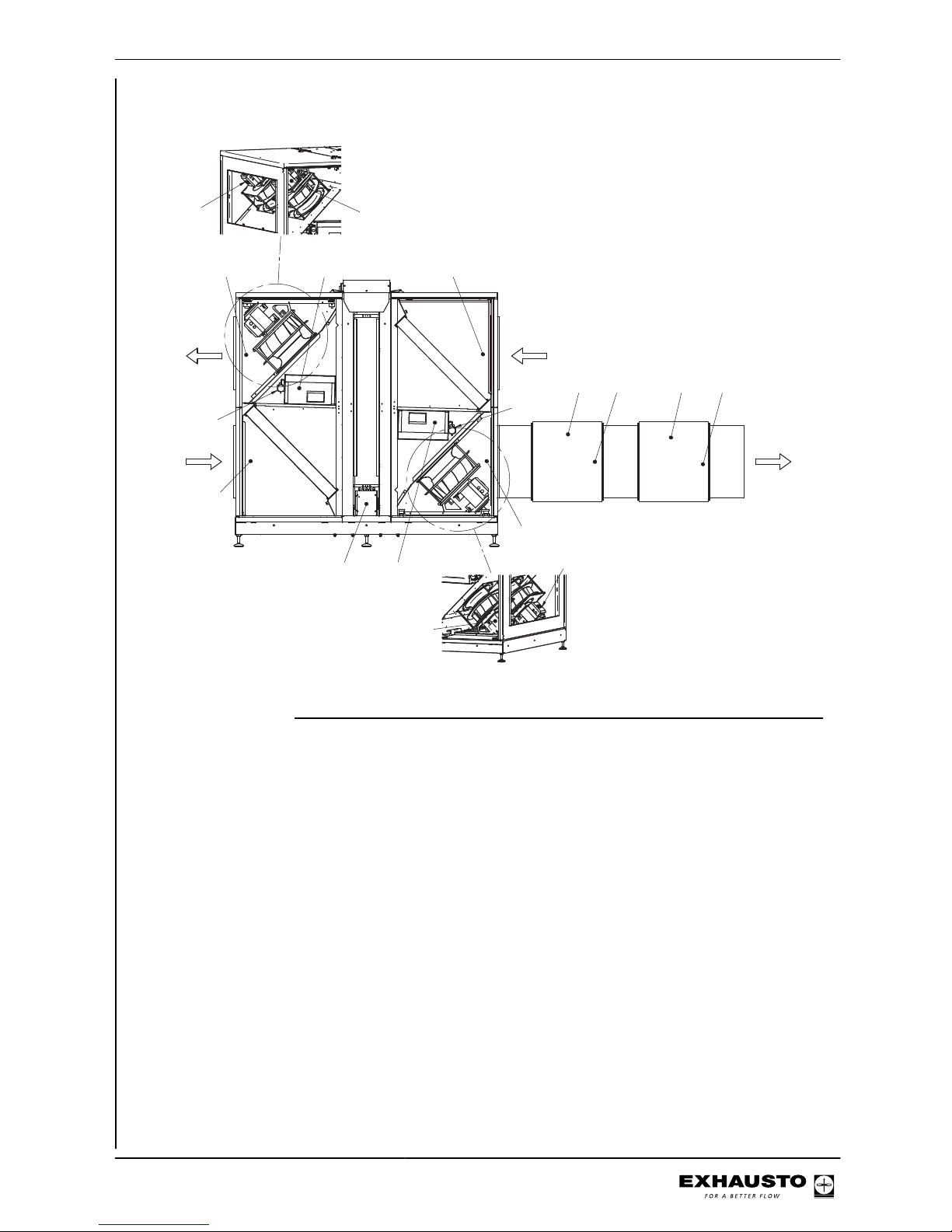
VEX280R fan placement 1
MC1
MC2
2,2,A
Supply air
2,1,A
Outdoor air
1,1,A
Extract air
1,2,A
Exhaust air
TE12
TE21
TE11
TE22
MPT1
MPT2
M1
M2
M2
M1
RHX2M
RD12921GB-02
HC CCW
T-heat
T-Cool
3003246-2014-05-21
Appendix 1 - Simplified diagrams
93/100
Page 94
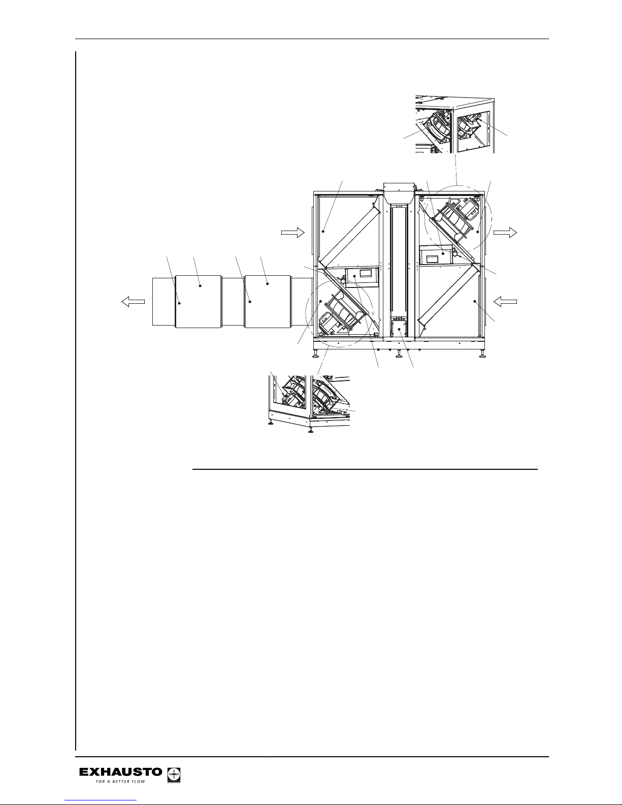
VEX280L fan placement 2
2,1,A
Outdoor air
RD12922GB-02
2,2,A
Supply air
1,1,A
Extract air
HCCCW
M2
TE22
TE11
MPT1
M1
MC1M1RHX2M
MC2
TE21
1,2,A
Exhaust air
TE12
MPT2
M2
T-heatT-Cool
3003246-2014-05-21
Appendix 1 - Simplified diagrams
94/100
Page 95
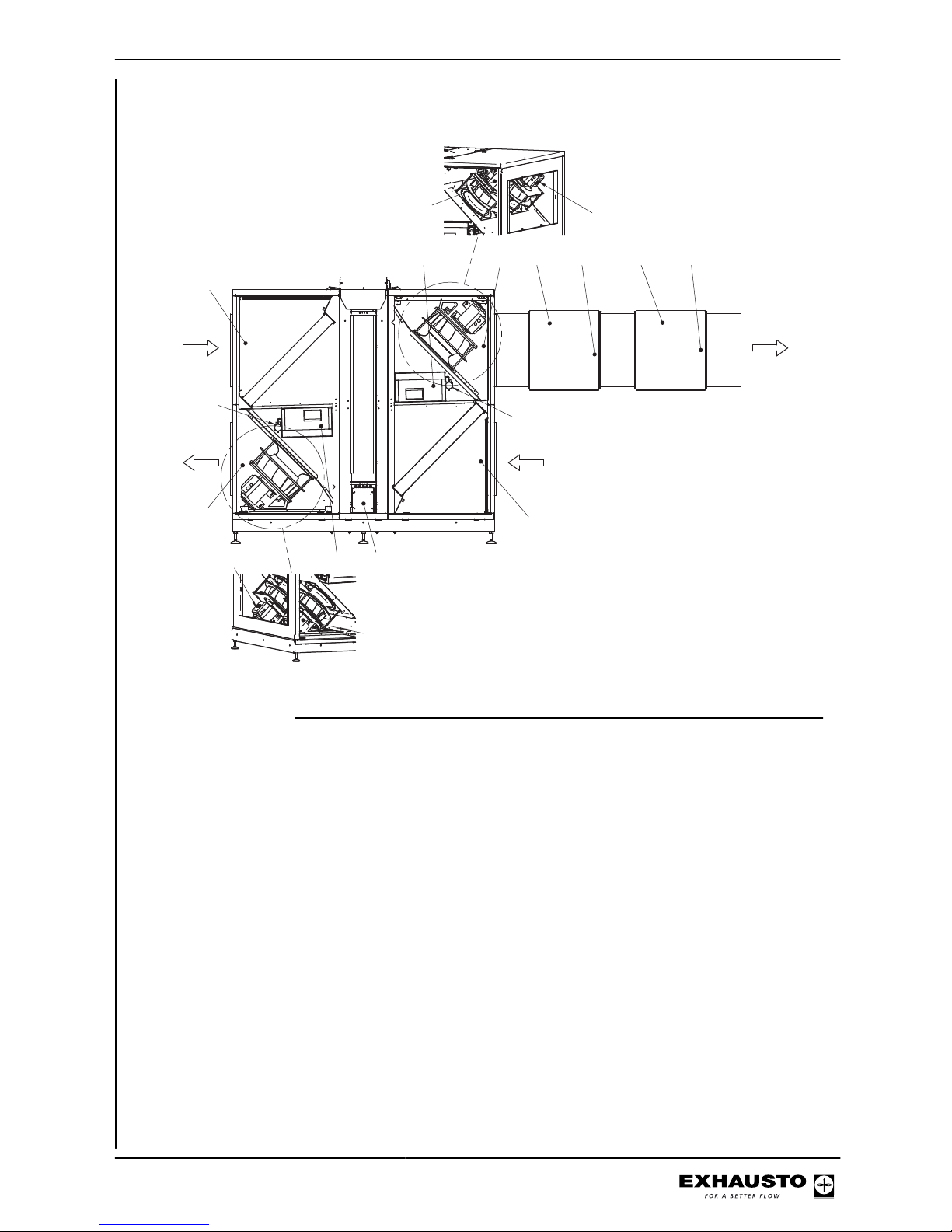
VEX280R fan placement 2
2,2,A
Supply air
RD12923GB-02
TE12
2,1,A
Outdoor air
TE21
MPT1
1,2,A
Exhaust air
M2
MC1M1RHX2M
MC2
M1
TE22
MPT2
TE11
HC
1,1,A
Extract air
M2
CCW
T-heat
T-Cool
3003246-2014-05-21
Appendix 1 - Simplified diagrams
95/100
Page 96
Appendix 2 - Temperature resistance table
Temperature resistance table DC95
Temperature
[°C]
Resistance
[Ohm]
Temperature
[°C]
Resistance
[Ohm]
Temperature
[°C]
Resistance
[Ohm]
-40 324270 -1 34464 38 5774
-39 320139 0 32737 39 5545
-38 299580 1 31107 40 5326
-37 280471 2 29567 41 5116
-36 262702 3 28113 42 4917
-35 246172 4 26739 43 4726
-34 230786 5 25440 44 4543
-33 216458 6 24211 45 4369
-32 203110 7 23049 46 4202
-31 190669 8 21950 47 4042
-30 179068 9 20910 48 3890
-29 168246 10 19924 49 3743
-28 158145 11 18991 50 3604
-27 148714 12 18107 51 3470
-26 139904 13 17270 52 3342
-25 131670 14 16476 53 3219
-24 123972 15 15722 54 3101
-23 116772 16 15008 55 2988
-22 110035 17 14330 56 2880
-21 103727 18 13687 57 2777
-20 97820 19 13076 58 2678
-19 92286 20 12496 59 2582
-18 87099 21 11945 60 2491
-17 82235 22 11421 61 2403
-16 77673 23 10923 62 2319
-15 73391 24 10450 63 2239
-14 69372 25 10000 64 2161
-13 65597 26 9572 65 2087
-12 62050 27 9164 66 2015
-11 58717 28 8776 67 1947
-10 55582 29 8407 68 1881
-9 52634 30 8055 69 1817
-8 49860 31 7720 70 1756
-7 47249 32 7401 71 1698
-6 44790 33 7097 72 1641
-5 42474 34 6807 73 1587
-4 40292 35 6530 74 1535
-3 38234 36 6266 75 1485
-2 36294 37 6014 76 1437
3003246-2014-05-21
Appendix 2 - Temperature resistance table
96/100
Page 97
Temperature
[°C]
Resistance
[Ohm]
Temperature
[°C]
Resistance
[Ohm]
Temperature
[°C]
Resistance
[Ohm]
77 1390 93 840,6 109 528,5
78 1346 94 815,7 110 514,0
79 1303 95 791,6 111 500,0
80 1261 96 768,4 112 486,4
81 1221 97 746,0 113 473,2
82 1183 98 724,3 114 460,5
83 1146 99 703,3 115 448,2
84 1110 100 683,1 116 436,3
85 1075 101 633,5 117 424,7
86 1042 102 644,6 118 413,5
87 1010 103 626,3 119 402,7
88 979,4 104 608,6 120 392,1
89 949,6 105 591,5 121 382,0
90 920,9 106 574,9 122 372,1
91 893,2 107 558,9 123 362,5
92 866,4 108 543,4 124 353,2
3003246-2014-05-21
Appendix 2 - Temperature resistance table
97/100
Page 98
3003246-2014-05-21
98/100
Page 99

3003246-2014-05-21
99/100
Page 100
 Loading...