

Exhausto RS 9, RS 16, RS 12, RS 14 Installation & Operating Manual
Installation & Operating Manual
NorthlineExpress.com
http://www.northlineexpress.com
Toll-Free 1-866-667-8454
USA
CAN
3000270 10.01
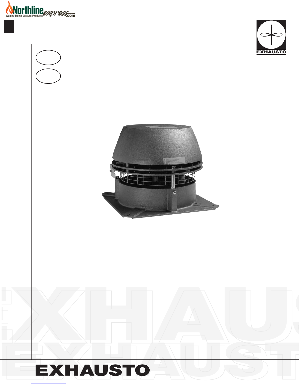
RS
Chimney Fan
For Gas & Oil Applications
1200 Northmeadow Parkway, STE 180 • Roswell, GA 30076
(770) 587-3238 (800) 255-2923 • Fax (770) 587-4731
info@exhausto.com • us.exhausto.com

Installation and adjustment instructions
NorthlineExpress.com
http://www.northlineexpress.com
Toll-Free 1-866-667-8454
for
EXHAUSTO
Chimney Fan Type
RS
Table of Contents:
1. Introduction
1.1 System Design .....................................................................................3
1.2 Code Compliance and Listings ............................................................3
1.3 Warranty Information............................................................................3
1.4 Package Shipment ...............................................................................3
1.5 Dimensional Data.................................................................................4
1.6 Planning Ahead....................................................................................5
2. Installing the Chimney Fan
2.1 Single Fan on Steel Chimney...............................................................6
2.2 Multiple Fans on Steel Chimney ..........................................................7
2.3 Single Fan on Brick Chimney...............................................................7
2.4 Multiple fans on Brick Chimney............................................................8
2.5 Wall Mounting of Chimney Fan ............................................................8
2.6 Installation for high temperatures.........................................................8
3. Installing Safety System
3.1 Installing Dwyer Pressure Switch.........................................................9
4. Wiring the Chimney Fan
4.1 General ..............................................................................................10
4.2 Wiring diagram for solenoid operated gas valve ................................ 11
4.3 Wiring diagram for burner control circuit ............................................ 11
5. System Start-Up
5.1 System testing....................................................................................12
5.2 Adjusting the Chimney Fan Speed.....................................................12
5.3 Adjusting the pressure switch setting.................................................12
6. Maintenance
6.1 Prior to Cleaning ................................................................................13
6.2 Care and cleaning ..............................................................................13
2/16
1. Introduction
!
NorthlineExpress.com
http://www.northlineexpress.com
Toll-Free 1-866-667-8454
1.1 System Design
EXHAUSTO model RS Chimney Fan is a chimney top mounted ventilator that is designed to provide large
ue gas volume capacities. It is designed and intended for use with oil/gas red central space heating
systems, for volume water heating or for combination space heating/volume water heating.
This product is developed to prevent draft problems from occurring by creating a mechanical draft in venting
systems and thereby also increasing the capacity and efciency of a venting system.
The use of the EXHAUSTO Chimney Fan is not restricted to any type of chimney, because the fan creates a
negative pressure (below atmospheric) in the chimney.
1.2 Code Compliance and Listings
Installations must conform to requirements of the authority having jurisdiction. Where required by the
authority having jurisdiction, the installation must also conform to the Standard for Draft Equipment.
All electrical wiring must be in accordance with the requirements of authority having jurisdiction or, in
absence of such requirements, with the National Electrical Code.
The EXHAUSTO Chimney Fan, Model RS, is tested by the ETL Testing Laboratories and is labeled and
listed for use with non-solid fuel applications.
Caution: The chimney fan must be interlocked with the connected appliance(s) to insure proper
combustion and to avoid ue gas spillage.
1.3 Warranty Information
Conditions available from EXHAUSTO, Inc.
1.4 Package Shipment
The packing list (attached to one of the packages) clearly lists all items in the shipment and each package
has a label showing the contents. Check the list against all materials on the job site for completeness.
Symbol Legend:
The following terms are used throughout this manual to bring attention to the presence of potential hazards or to
important information concerning the product.
Danger: Indicates an imminently hazardous situation which, if not avoided, will result in death, serious injury or
substantial property damage.
Caution: Indicates an imminently hazardous situation which, if not avoided, may result in personal injury or
property damage.
Warning: Indicates an imminently hazardous situation which, if not avoided, will result in death, serious injury
or substantial property damage.
Notice: Used to notify of special instructions on installation, operation or maintenance which are important to
equipment but not related to personal injury hazards.
3/16

1.5 Dimensional Data
NorthlineExpress.com
http://www.northlineexpress.com
Toll-Free 1-866-667-8454
Fan Size RS 9 RS 12 RS 14 RS 16
A 10 11 13 16
B 12 14 16 19
C 11 2/5 14 15 4/5 18
D 3 3 3/5 4 4
E 8 1/2 11 1/8 12 3/4 14 3/4
Weight (lbs) 28 36 46 60
Elec. Character 120/1/60
Amps 0.4 1.2 1.4 3.9
Watts 20 80 100 250
RPM 1600
Max. CFM 450 950 1400 2000
1 Junction Box 7 Base Plate
2 Conduit/cord 8 Locking Nut
3 Motor 9 Inlet
4 Motor Housing 10 Axial Vane
5 Cooling Plates 11 Hinges
6 Bird Screen
4/16

1.6 Planning Ahead
NorthlineExpress.com
http://www.northlineexpress.com
Toll-Free 1-866-667-8454
Important to note:
1. Observe proper combustion air requirements.
2. Provide a rm support system for the chimney fan.
3. Determine the type of system involved.
4. Observe proper safety measures are taken to assure system will shut down in case of insufcient
draft in vent system.
Combustion Air Requirements: Provisions for combustion air must be in accordance with applicable
local codes.
If the heating system is installed in an unconned space, adequate air will be available via normal
inltration.
If the heating system is installed in a conned space, (a space with a volume of less than 50 cubic feet
per 1000 Btu/hr of input for all fuel burning equipment) or building construction is unusually tight, adequate
air for combustion must be provided by two openings: one located about 6” below the ceiling, the other
about 6” above the oor. Each opening must have a minimum free area as follows:
1. One square inch per 4000 Btu/hr of input when communicating directly with the outside or through
a vertical duct.
2. One square inch per 2000 Btu/hr of input when communicating through horizontal ducts to outside.
3. One square inch per 1000 Btu/hr of input when ventilation air is provided by openings in doors, etc.
to adjoining spaces having adequate inltration.
Warning: Adequate fresh air must be provided for combustion; otherwise, improper operation and inadequate
venting of deadly ue gases may result.
Support system for the chimney fan: Prior to installation of the chimney fan, it must be assured the
chimney can safely carry the weight of the chimney fan.
A steel chimney should be well supported at the roof penetration point. If the chimney extends more
than 20’ above the roof, the chimney and the fan should be secured by wires attached on the chimney
and on the roof at 2 to 3 different points.
Brick chimneys usually do not need any kind of support to carry the weight of the chimney fan.
System Type
To determine the type of system is important in order to understand what to expect from the system.
Direct connect oil or gas appliances (no draft hood) normally do not require any mechanical draft
adjustment. However, if there are long horizontal breechings and far between the appliances, it is a good
idea to install mechanical vent-dampers, so adjustments of the draft can easily be made.
Draft hood systems should generally speaking have vent dampers installed. The vent dampers are used to
balance the system and assure that only a minimum of dilution air is pulled through the draft hoods.
Safety Devices
Local codes usually require installation of safety devices, when mechanical draft is provided in an oil or
gas fueled system.
Make sure a differential pressure switch (fan proving switch) is installed to assure that no appliance will
re unless there is a proven draft.
5/16
 Loading...