

Exhausto GSV 200-450, GSV 200, GSV 250, GSV 315, GSV 400 Installation & Operating Manual
...
3001391 01.07
CM
I
N
T
E
R
T
E
K
L
I
S
T
E
D
C US
Installation & Operating Manual
GSV 200-450 Grease Fan
USA
CAN
Product Information
Mechanical Installation
Electrical Installation
Start Up and Conguration
Maintenance and Troubleshooting
EXHAUSTO Inc.
1200 Northmeadow Pkwy.
Suite 180
Roswell, GA 30076
P: 770.587.3238
F: 770.587.4731
T: 800.255.2923
info@exhausto.com
us.exhausto.com
........................ Chapter 1 + 2
......................... Chapter 3
............................. Chapter 4
.................. Chapter 5
...... Chapter 6
Job Name:
Installer:
Installation Date:
3001391 01.07
!
!
!
1. Product Information
1.1 Function .....................................................................................................3
1.2 Components ...............................................................................................3
1.3 Shipping .....................................................................................................4
1.4 Warranty .....................................................................................................4
2. Specications
2.1 Dimensions & Capacities ...........................................................................4
3. Mechanical Installation
3.1 Positioning ..................................................................................................5
3.2 Installation on Steel Duct ...........................................................................5
3.3 Installation on Roof Curb ............................................................................5
4. Electrical Installation
4.1 Electrical Requirements .............................................................................6
4.2 Wiring Diagram for GSV 250-315 ..............................................................6
4.3 Wiring Diagram for GSV 400-450 ..............................................................7
4.4 Start-up ......................................................................................................8
5. Start-up & Conguration
5.1 Start-up ......................................................................................................8
6. Maintenance & Troubleshooting
6.1 Maintenance Intervals ............................................................................... 9
6.2 Cleaning ..................................................................................................... 9
6.3 Spare Parts Ordering .................................................................................9
Symbol Legend:
The following terms are used throughout this manual to
bring attention to the presence of potential hazards or to
important information concerning the product.
Danger: Indicates an imminent hazardous
situation which, if not avoided, will result in death,
serious injury or substantial property damage.
Caution: Indicates an imminent hazardous
situation which, if not avoided, may result in
personal injury or property damage.
TO REDUCE THE RISK OF FIRE, ELECTRICAL SHOCK OR INJURY TO PERSONS,
OBSERVE THE FOLLOWING:
1. Use this unit in the manner intended by the
manufacturer. If you have questions, contact the
manufacturer at the address or telephone number listed
on the front of the manual.
2. Before servicing or cleaning the unit, switch off at service
panel and lock service panel to prevent power from being
switched on accidentally.
3. Installation work and electrical wiring must be done by a
qualied person(s) in accordance with applicable codes
and standards.
4. Follow the appliance manufacturer’s guidelines and
safety standards such as those published by the
National Fire Protection Associations (NFPA), and the
American Society for Heating, Refrigeration and Air
Conditioning Engineers (ASHRAE), and the local code
authorities.
5. This unit must be grounded.
How to use this manual
This installation manual does not contain any system
design documentation. System design documentation is
available from any authorized EXHAUSTO representative.
Accessories, like roof curbs and variable frequency drives,
are not covered by this manual. Please refer to these
component’s individual manuals.
2
3001391 01.07
1. Product Information
1.1 Function
Use EXHAUSTO Model GSV Grease Fan is designed to provide a large exhaust volume at a high discharge
velocity. It is intended for use as a part of a restaurant kitchen exhaust system and grease applications
according to NFPA 96.The use of the EXHAUSTO Grease Fan is not restricted to any type of chimney or
grease duct. However, always follow the exhaust-hood manufacturer’s instructions regarding the venting.
Construction
The fan housing is made of heavy cast aluminum and can be opened for easy cleaning. The impeller
is of the backward inclined type. It is made of cast aluminum and has permanently attached balancing
weights.
The motor is a direct-drive, variable speed, class H insulated, high temperature motor. It has permanently
lubricated and sealed ball bearings and is maintenance free.
Listings Installations must conform to the requirements of the authority having jurisdiction. Where required by the
authority having jurisdiction, the installation must also conform to the NFPA 96. All electrical wiring must
be in accordance with the requirements of authority having jurisdiction or, in absence of such
requirements, with the National Electrical Code, NFPA 70.
EXHAUSTO Model GSV is tested and listed to UL Standard 705 for Power Ventilators and UL Standard
762 for Power Ventilators for Restaurant Exhaust Ventilators.
The model is also tested and listed to ULC-S645-93, Standard for Power Roof Ventilators for Commercial
and Institutional Kitchen Exhaust Systems.
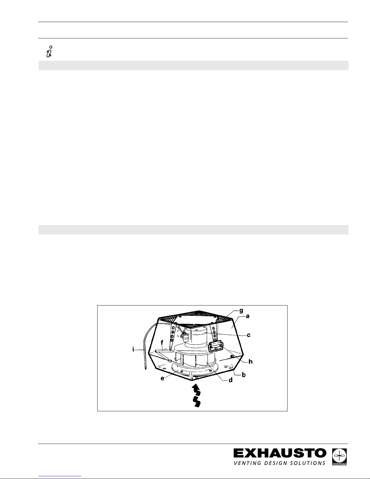
1.2 Components
The GSV Grease Fan consists of the following components:
a. Top section f. Locking hinge
b. Bottom section g. Bird screen
c. Motor h. Carrying handle
d. Centrifugal impeller i. Wiring conduit
e. Inlet for impeller
Fig. 1
Max. 575°F (300°C)
3
3/12
3001391 01.07
!
1.3 Shipping
Protection The fan is shipped in a corrugated cardboard box. If a transport securing device is attached (GSV 400 and
GSV 450 only) to the bottom of the fan to hold the motor and impeller in place, do not remove it when
unpacking the fan.
Do not remove the transport securing device until the fan is being installed on the duct or
the roof curb. The motor shaft could be damaged.
NOTE:
All single phase fans are shipped with a capacitor and junction box connected via conduit. The capacitor is
located INSIDE the junction box. Please do not discard.
1.4 Warranty
EXHAUSTO products are warranted for a period of two (2) years following the date of invoice.
Replacement or repair will be at EXHAUSTO’s discretion, provided factory inspection shows a defect
in material or workmanship.
Complete warranty conditions are available from EXHAUSTO.
2. Specications
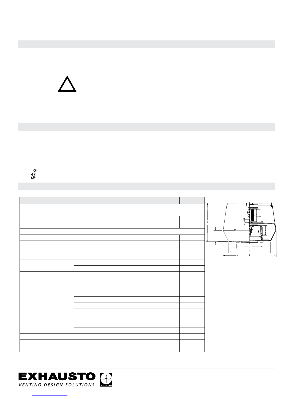
2.1 Dimensions & Capacities
Model
Discharge Vertical
Fan Type Centrifugal Impeller
Max. Discharge Velocity FPM 1,729 2,222 2,771 2,752 4,134
Actual Discharge Velocity FPM 2.9xCFM 1.9xCFM 1.2xCFM 1.03xCFM 1.03xCFM
Voltage VAC 1 x 120 3x208-240 / 3x380-420
RPM 1600 1680 1720
Amps A 1.4 2.9 5.8 3.5 6.5
Power Ratings kW 0.10 0.16 0.35 0.75 1.5
Weight lbs 47 60
Dimensions A in 11.03 13.20
B x B in 15.37 19.11
C x C in 12.22 15.17
D Ø in 7.88 9.85
E in 3.15 3.94
Soft Start Required No No No Yes
Variable Speed Motor Yes Yes Yes Yes Yes
FA Sones 3.9 6.3 7.8 8.3
GSV 200 GSV 250 GSV 315 GSV 400 GSV 450
0.15 0.2 0.5 1.0 2.0
kg 18 26
mm 280 335
mm 390 485
mm 310 385
mm 200 250
mm 80 100
92
42
16.94
430
25.61
650
20.69
525
15.76
400
5.12
130
127 155
58 70
16.94 23.23
430 590
25.61 25.61
650 650
20.69 20.69
525 525
15.76 15.76
400 400
5.12 8.54
130 217
1)
Yes
1)
1) Not required if using a VFD
4
 Loading...