

Exhausto VEX200 series, EXact2 VEX240 series, EXact2 VEX250 series, EXact2 VEX260 series, EXact2 VEX270 series Basic Instructions
...
EXact Control System
Basic instructions for the VEX200 series
EXHAUSTO
OK
EXHAUSTO
Esc
OK
Original instructions
3003246-2014-05-21
EXact_VEX200
EXHAUSTO A/S
Odensevej 76
DK-5550 Langeskov
Tel. +45 65 66 12 34
Fax +45 65 66 11 10
exhausto@exhausto.dk
www.exhausto.dk
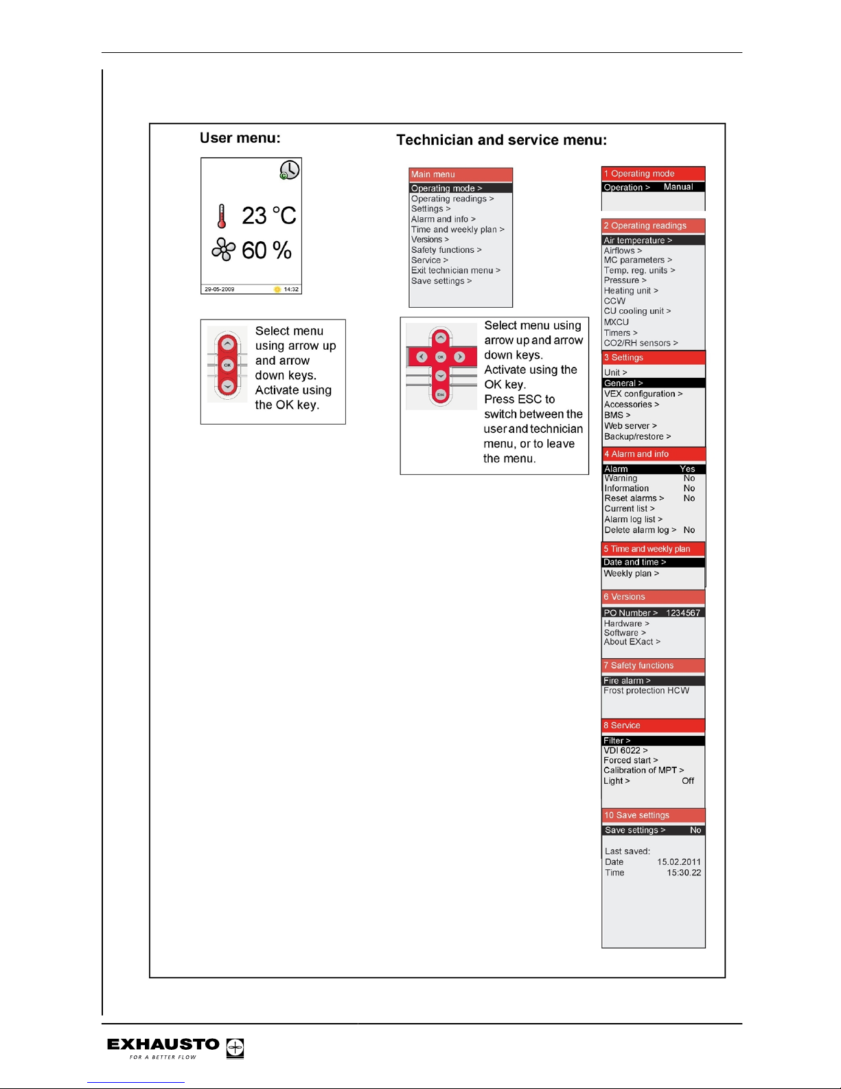
Menu structure
3003246-2014-05-21
2/100

Symbols and software version
Symbols used in these instructions...........................................................................5
Software version...........................................................................................................5
Software version .......................................................................................................5
2. User mode
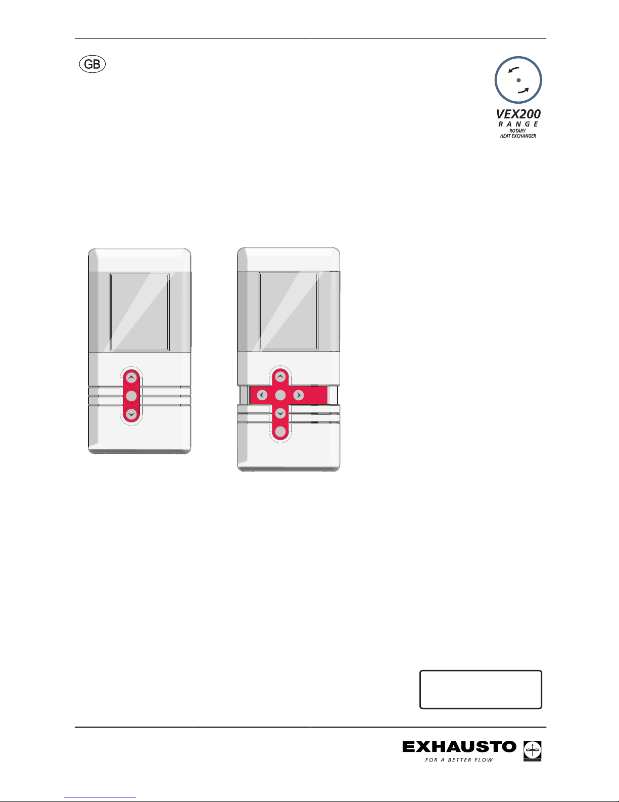
2.1. HMI panel................................................................................................................6
2.2. Display icons..........................................................................................................7
3. Operation, access codes and selecting language
3.1. Using the HMI panel..............................................................................................9
3.1.1. Using keys within the menus...........................................................................9
3.2. Access codes for technician and service menus.............................................10
3.3. IMPORTANT when servicing..............................................................................11
3.3.1. Auxiliary service panel...................................................................................12
Menu 3.2 - Selecting language..................................................................................13
Menu 3.2.1 - Setting date and time............................................................................13
Menu 3.2 - Reset settings...........................................................................................13
Menu 3.2 - Reload database.......................................................................................14
Menu 3.6 - Web server................................................................................................14
Menu 3.7 - Backup/restore.........................................................................................15
4. Starting unit operation
4.1. Getting started.....................................................................................................16
Start configuration....................................................................................................17
Menu 3.4 - Accessories...........................................................................................18
Menu 3.4 Connecting heating and cooling units .....................................................19
Menu 3.5 BMS.............................................................................................................20
Menu 3.5 - BMS.......................................................................................................20
4.3. What is an indoor air quality level?...................................................................20
Menu 1 - Selecting operating mode..........................................................................21
Menu 3.1.1 - Operating settings - Air regulation......................................................21
Menu 3.1.1 - Operating settings Balance................................................................23
Menu 3.1.1.5 Regulators ........................................................................................24
Menus 3.1.1.1.1 to 3.1.1.1.4 Configuring the selected indoor air quality levels....25
Menu 3.1.1.1.x - Air set point ..................................................................................25
Menu 3.1.1.1.x - Temperature set point ..................................................................25
Menu 3.1.1.1.x - Absolute / Relative temperature ..................................................25
Menu 3.1.1.1.x - Cooling relative start ....................................................................26
Menu 3.1.1.1.x - Heating relative start ....................................................................26
Menu 3.1.1.1.x - Cooling absolute start ..................................................................26
Menu 3.1.1.1.x - Heating absolute start ..................................................................27
Generally on temperature regulation ......................................................................27
Menu 3.1.8 - Temperature limits..............................................................................27
Menu 3.1.1.1.x - Supply air regulation, absolute ....................................................29
Menu 3.1.1.1.x - Room temperature regulation, absolute ......................................30
Menu 3.1.1.1.x - Supply air regulation, relative ......................................................31
Menu 3.1.1.1.x - Room temperature regulation, relative ........................................33
Menu 3.1.1 - Operation settings - Temperature regulation.....................................35
Compensation.............................................................................................................36
Menu 3.1.2 - Air compensation..................................................................................36
Menu 3.1.2.1 - CO2 compensation .........................................................................37
Menu 3.1.2.2 - Humidity compensation of airflow ...................................................38
Menu 3.1.2.3 - Airflow reduction .............................................................................38
Menu 3.1.2.4 - Outdoor compensation of airflow ....................................................39
Menu 3.1.3 - Temperature compensation.................................................................40
Outdoor air temperature compensation (menu 3.1.2.1) ..........................................40
Summertime compensation (menu 3.1.2.2) ............................................................41
Menu 3.1.4 + Menu 8.1 - Filter (monitoring in case of pressure) ............................41
Menu 3.1.4 + Menu 8.1 - Filter (monitoring with hour counter) ...............................42
Menu 3.1.5 - Night-time cooling ..............................................................................42
Menu 3.1.6 - Cold recovery.....................................................................................45
Menu 3.1.7 - Fan limits............................................................................................45
3003246-2014-05-21
3/100

Menu 3.1.8 - Temperature limits for supply air and room........................................45
Room temperature limits..........................................................................................46
Menu 3.1.9 - Cooling/heat pump unit ......................................................................46
Menu 5 - Time and weekly plan.................................................................................47
Menu 5.1 - Date and time........................................................................................47
Menu 5.2 - Weekly plan ..........................................................................................48
Menu 7 - Safety functions..........................................................................................49
Menu 7.1 - Fire alarm..............................................................................................49
Menu 7.2 - Frost protection of HCW .......................................................................50
5. Operation
Menu 2 - Operating readings.....................................................................................52
Menu 2.1 - Air temperatures ...................................................................................52
Menu 2.1.1 - Set points for regulators ....................................................................53
Menu 2.2 - Airflows .................................................................................................53
Menu 2.3 - Motor controller parameters (MC parameters) .....................................53
Menu 2.4 - Temperature regulating units ................................................................54
Menu 2.5 - Pressure................................................................................................54
Menu 2.6 - Heating coil ...........................................................................................54
Menu 2.7 - Cooling/heat pump unit .........................................................................55
Menu 2.8 - CCW cold water coil .............................................................................55
Menu 2.9 - CU cooling unit......................................................................................55
Menu 2.10 - MXCU external cooling unit.................................................................55
Menu 2.11 - Hour counters......................................................................................56
Menu 2.12 - CO2/RH sensors (if mounted).............................................................56
Menu 6 - Versions.......................................................................................................56
Menu 8 - Service.........................................................................................................57
Auxiliary service panel.............................................................................................58
Menu 8.2 - VDI 6022................................................................................................59
Menu 8.3 - Forced start ..........................................................................................59
Menu 8.3.1 Fans......................................................................................................59
Menu 8.3.2 Recovery...............................................................................................59
Menu 8.3.3 Heating unit...........................................................................................60
Menu 8.3.4 Cooling unit...........................................................................................60
Menu 8.3.5 Dampers and relays..............................................................................60
Menu 8.4 - Calibrating MPT.....................................................................................60
6. Alarms
6.1. Alarms and info (Menu 4)....................................................................................62
6.2. Reset alarms........................................................................................................62
6.3. Alarm display – causes of errors.......................................................................62
6.4. List of alarms.......................................................................................................64
Appendix 1 - Simplified diagrams
Simplified diagrams....................................................................................................90
Simplified diagrams for unit with chiller ...................................................................90
VEX240-250-260-270L fan placement 1 ................................................................90
VEX240-250-260-270L fan placement 1 ................................................................90
VEX240-250-260-270L fan placement 2 ................................................................91
VEX240-250-260-270L fan placement 2 ................................................................91
VEX280L fan placement 1 ......................................................................................92
VEX280R fan placement 1 .....................................................................................93
VEX280L fan placement 2 ......................................................................................94
VEX280R fan placement 2 .....................................................................................95
Appendix 2 - Temperature resistance table
Temperature resistance table DC95..........................................................................96
3003246-2014-05-21
4/100
Symbols and software version
Symbols used in these instructions
Prohibition symbol Failure to observe instructions marked with a prohibition symbol
may result in serious or fatal injury.
Danger symbol Failure to observe instructions marked with a danger symbol may
result in personal injury and/or damage to the unit.
Software version
Software version
These instructions are for use with the following version:
AHUC: 3.2.0.0
HMI: 3.2.0.0
3003246-2014-05-21
Symbols and software version
5/100
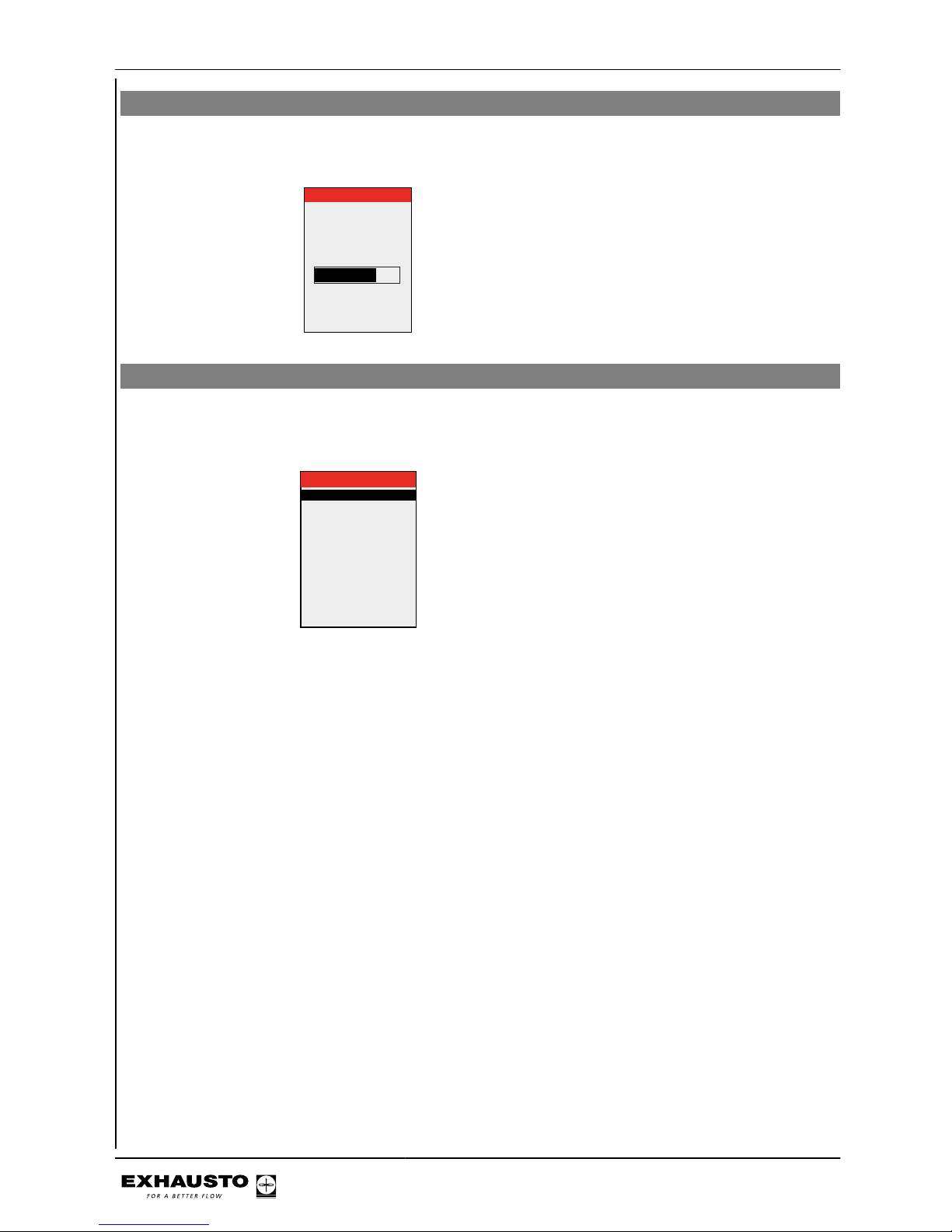
2. User mode
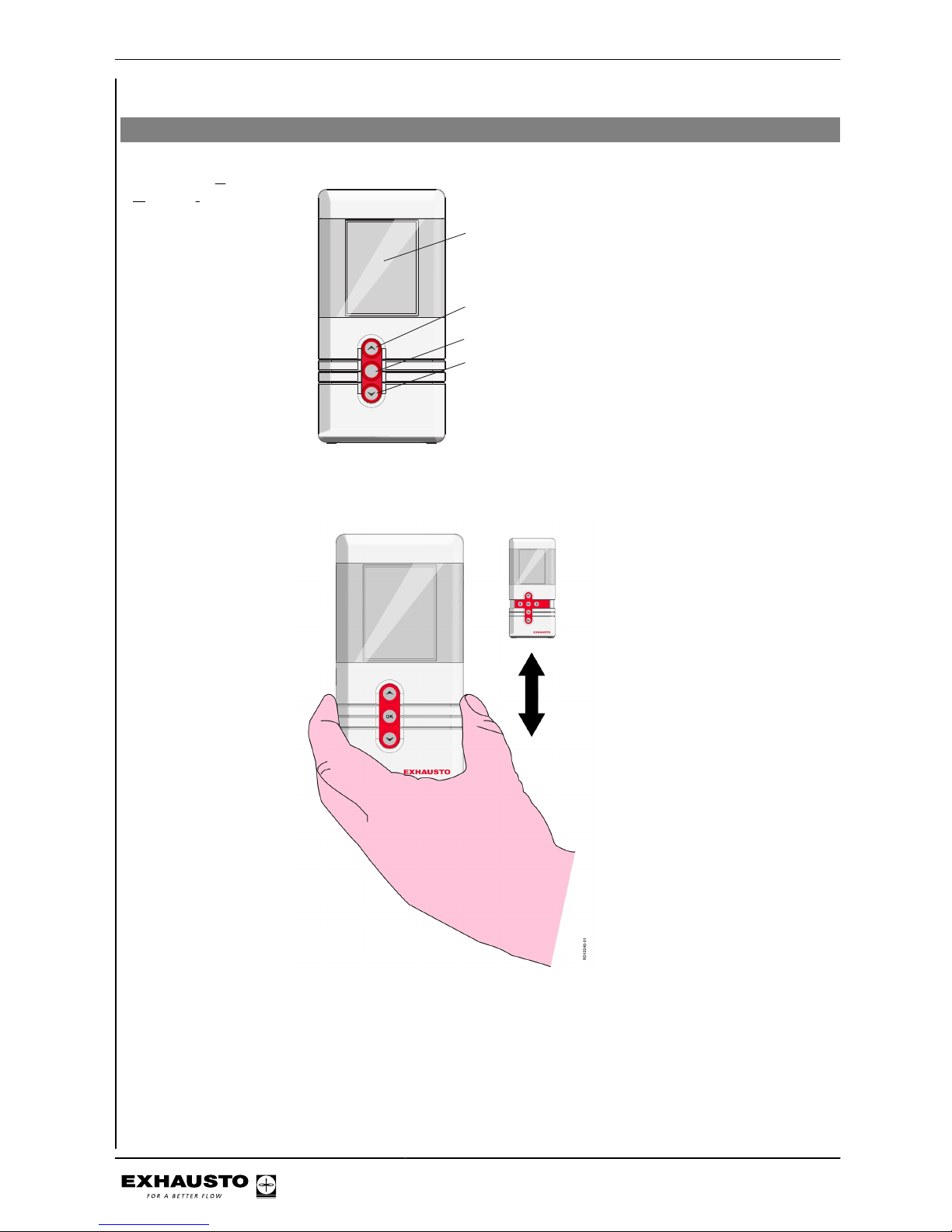
2.1 HMI panel
HMI panel - Human
Machine Interface
panel
mode
EXHAUSTO
OK
RD12248-01
Display
Browse menu or
set value
Activate menu/confirm key
Browse menu or
set value
If the front cover is extended, push it back in. The extra keys are for service technician use only.
3003246-2014-05-21
User mode
6/100
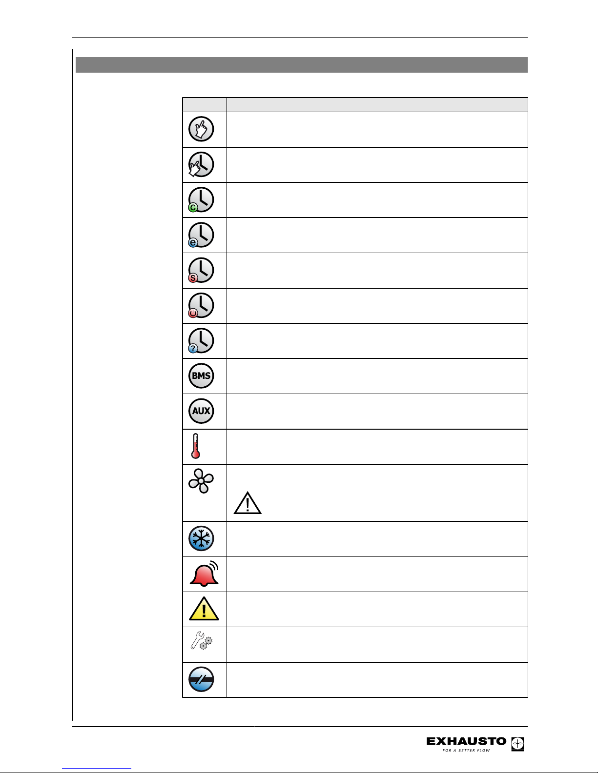
2.2 Display icons
Icon Description
Manual operation
Timer overridden until next changeover in the timer schedule
Timer, current indoor air quality level is comfort
Timer, current indoor air quality level is economy
Timer, current indoor air quality level is standby
Timer, VEX has stopped
Timer, no changeover times defined in timer schedule
BMS-controlled operation
Externally-controlled operation
Set point for temperature shown in °C
Set point for ventilation shown as percentage: 0% = no ventilation OFF =
Unit is switched off - timer function cannot start up unit
BMS or Web server-controlled system overrides the OFF function. This means the system may start up even if set to OFF
The unit is running de-icing (De-ice)
Unit alarm. Contact the service technician who can help reset the alarm.
Icon is also shown in the technician menu
Warning. Contact the service technician who can help reset the warning.
Icon is also shown in the technician menu
Temporarily
in service
Service display connected
External start/stop disconnected. See Electrical Installation Guide for further information
3003246-2014-05-21
User mode
7/100

Icon Description
Summertime
Wintertime
No communication on the external BUS or communication between the
VEX and HMI is disconnected
Fire!
Fire alarm. Closed circuit open and the pre-set fire alarm function activated
Startup: Web server accessing database. The icon is displayed until the
HMI panel is ready for use.
3003246-2014-05-21
User mode
8/100
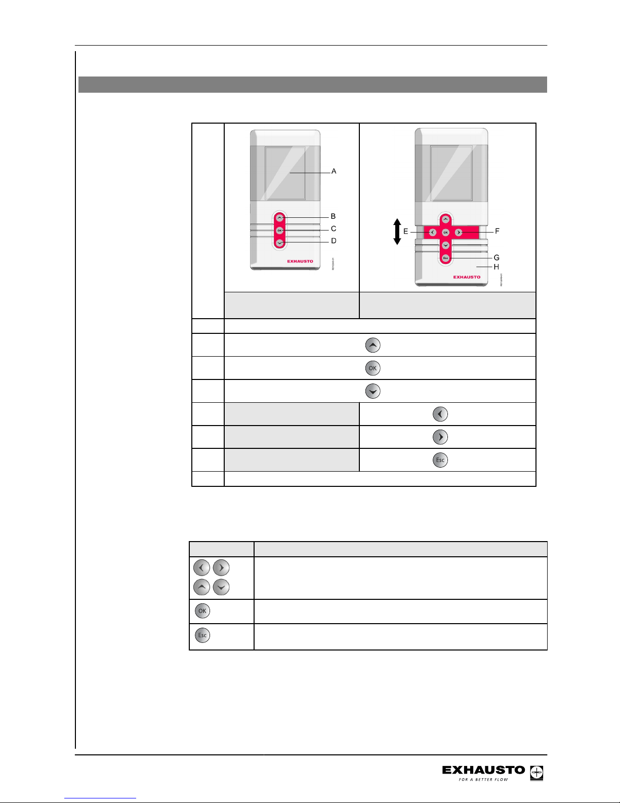
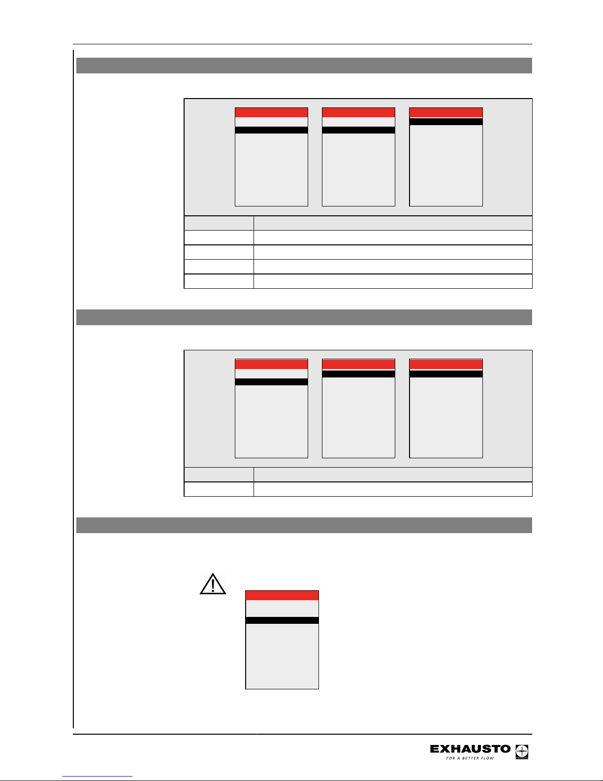
3. Operation, access codes and selecting language
3.1 Using the HMI panel
Keys for user mode
or service mode
HMI panel ready for everyday use
HMI panel ready for service mode
A Display
B
key
C
key
D
key
E
key
F
key
G
key
H Service key cover
3.1.1 Using keys within the menus
Keys Used for...
Navigation and setting values
Confirm key - selecting menu
Change between daily user and technician mode
Exiting a menu without making changes
3003246-2014-05-21
Operation, access codes and selecting
language
9/100
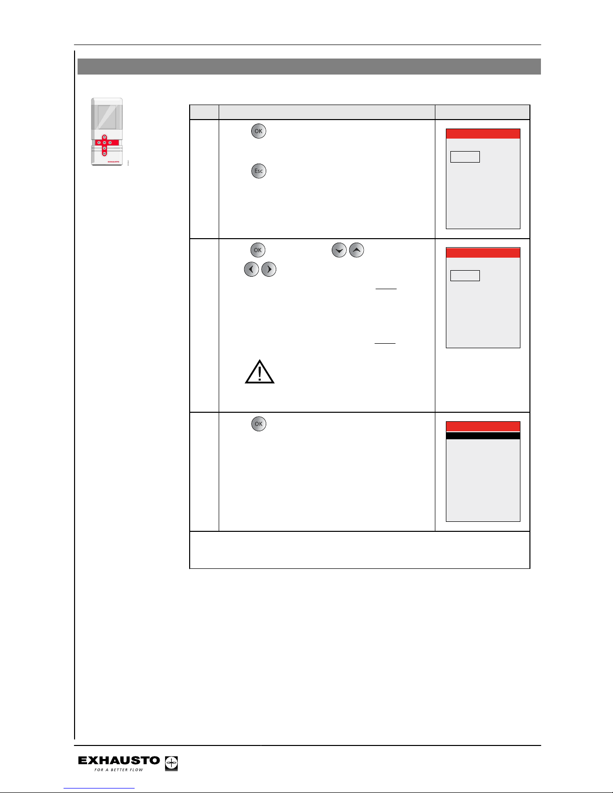
3.2 Access codes for technician and service menus
Step Action The display shows
1
Press for full display brightness (if the display
is in hibernation mode).
Press
Password
0000
2
Press and then press to set the value.
Use to shift to the next digit of the code.
● The code for technician mode is
1111 (some
menus are hidden or read-only). EXHAUSTO
recommends this mode is used for normal
service tasks
● The code for specialist mode is 3142 (full ac-
cess to all menus).
NB: incorrect settings (wrong val-
ues) may have a negative impact on unit
operation in some menus
Password
1111
3
Press to access main menu.
Main menu
Operating mode >
Operating readings >
Settings >
Alarm and info >
Time and weekly plan >
Versions >
Safety functions >
Service >
Exit technician menu >
Save settings >
Note
● Automatically logs out and returns to the user menu if no buttons are pressed
in a 30-minute period.
3003246-2014-05-21
Operation, access codes and selecting
language
10/100
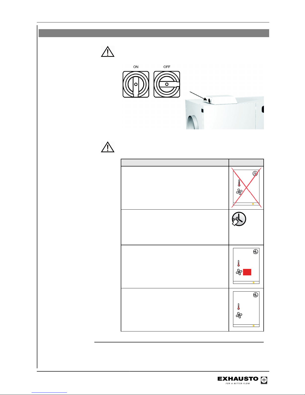
3.3 IMPORTANT when servicing
Do not open the service doors before the supply voltage has been disconnec-
ted at the isolation switch. The isolation switch is positioned on
the left side of the connection box on top of the unit.
Weekly plan It is important to set ventilation to OFF when the weekly plan is
active:
Set ventilation to OFF
NB - If the HMI panel shows 0% (VEX is inactive)
and the unit is operating to a weekly plan when
servicing begins, there is a risk that the program may change via a timer operation and restart the VEX unit.
21
0°C%
29-05-2009 14:32
● Log onto technician menu, using password 1111
● Change to manual operation via menu 1
● Change back to user menu
● The icon for manual operation appears in
the right-hand corner of the menu
● Press the OK button twice
● Use the arrow keys to adjust ventilation to
0%
23 °C
%
29-05-2013 14:32
0
● Press OK
● OFF will now appear on the display next to
the ventilation icon
23 °C
29-05-2013 14:32
OFF
3003246-2014-05-21
Operation, access codes and selecting
language
11/100

BMS unit or Web
server
If BMS or Web server controls are used, they could override the
OFF function and the VEX may start up irregularly. To disconnect
the BMS or WEB server connection, you must remove the plug
from the connection board. Refer to the section on the terminal
board in the Electrical Installation Guide.
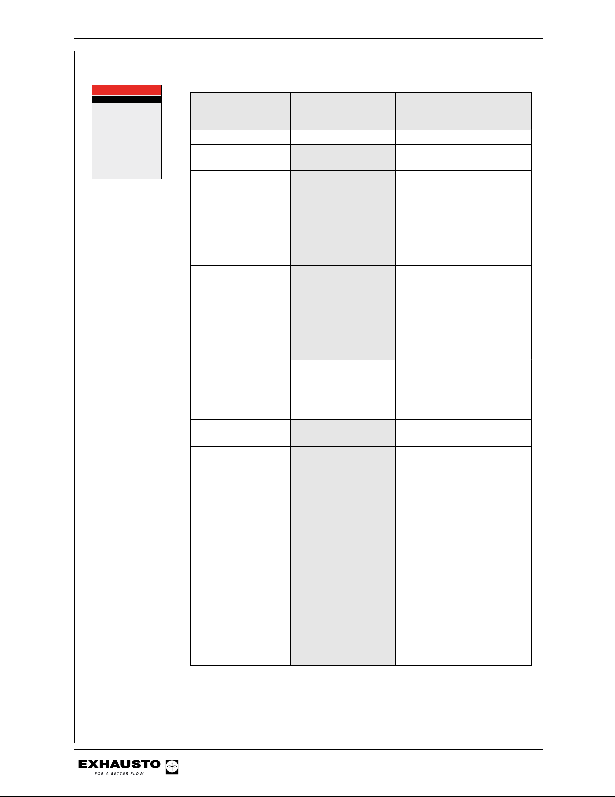
3.3.1 Auxiliary service panel
If the HMI panel is located far from the VEX, it is recommended that an auxiliary HMI
panel be connected to the VEX in the connection box.
RD12627-02
Auxiliary service panel which
overrides the fixed HMI panel
Fixed HMI-panel
Service panel connector - Exact
3003246-2014-05-21
Operation, access codes and selecting
language
12/100
Menu 3.2 - Selecting language
Unit >
General >
VEX configuration >
Accessories >
BMS >
Web server >
Backup/restore >
3 Settings
3.2 General
Date and time >
Language >
Reset settings >
Reload database >
English
Main menu
Operating mode >
Operating readings >
Settings >
Alarm and info >
Time and weekly plan >
Versions >
Safety functions >
Service >
Exit technician menu >
Save settings >
Step Action
1 Select "Settings"
2 Select "General"
3 Select the required language in line 2 "Language"
4 Return to the main menu and select yes in "Save settings"
Menu 3.2.1 - Setting date and time
Unit >
General >
VEX configuration >
Accessories >
BMS >
Web server >
Backup/restore >
3 Settings
3.2 General
Date and time >
Language >
Reset settings >
Reload database >
English
3.2.1 Date and time
Date > 22-02-2009
Day >
Time >
Wednesday
13:11
Step Action
1 Select "Date and time" to set these parameters in Menu 3.2.1
Menu 3.2 - Reset settings
Selecting "Reset settings" resets the user settings. See the menu guide for details of
which menus are affected.
NB This cannot be reversed and the VEX will restart.
3.2 General
Date and time >
Language >
Reset settings >
Reload database >
English
3003246-2014-05-21
Operation, access codes and selecting
language
13/100
Menu 3.2 - Reload database
Selecting "Reset settings" resets the user settings. See the menu guide for details of
which menus are affected.
Database reloads
Initialising
Loading DB names
Menu 3.6 - Web server
Contact the network administrator for information on the correct IP address, etc. If the
admin password is lost, it can be reset to the factory setting. But note that this cannot
be reversed. See Exact Web server Instructions.
No
> 192.168.001.180
> 255.255.255.000
> 192.168.001.001
80
00:1F:79:00:00:D0
No
3.6 Web server
DHCP >
IP address
Subnet mask
Standard gateway
Port number >
MAC address
Reset password >
3003246-2014-05-21
Operation, access codes and selecting
language
14/100

Menu 3.7 - Backup/restore
It is recommended that a backup copy of the VEX settings is made and saved on a
secure media. See the individual backup guidelines in the diagram:
+
Backup via the HMI panel
● Insert the USB plug in one of the web
server sockets
● Select menu Backup/restore
● It can take up to 20 seconds to establish
the connection to the USB
The backup file can only be saved on a USB
plug. Once the file has been saved it is not
possible to change the file name or type.
The file is named automatically as in this example: backup_20110918.file
Backup via web server
Follow the backup/restore instructions in the
web server guide. The backup file may be
saved on any medium (USB, PC etc.).
A backup file saved via the web server may
be renamed, but the file type cannot be
changed.
NB
If a backup file has been saved from the web
server and then renamed, it cannot be retrieved (restored) via HMI until the name has
been changed back to the standard form, see
"Via HMI panel".
If it is necessary to make backup files for several VEX, it is recommended that each file is
saved on a separate USB flash drive or that
a folder is created for each VEX on which the
backup files can be saved.
3003246-2014-05-21
Operation, access codes and selecting
language
15/100
4. Starting unit operation
The Modbus connectors must not be connected or removed while the
units are powered up. Both Modbus units must be switched off before
making changes, otherwise the units may be damaged.
During commissioning, it may be necessary to work with the control
system boxes open. Components in these boxes must only be touched
with electrically-insulated tools.
Before doing any work on motor controls or motor cables and terminal
boxes, the power supply must be switched off for at least five minutes
to allow the capacitors to discharge.
Before commissioning begins
● Check that the supply voltage is connected
● Set the HMI panel to specialist mode. See section 2.2
4.1 Getting started
From the main menu, follow the steps below to start the commissioning process.
Commissioning
Step Action Menu
1 Configure any external accessories or units (heating or
cooling coils (CCW, MXCU), chiller, sensors, etc.)
3.4
2 Select operating mode - Manual operation is the recom-
mended setting during commissioning
1
3 Set/activate operation settings 3.1
4 Program weekly plan 5.2
5 Set safety function settings 7
6 Select operating mode - change to timer operation if re-
quired
1
The various menu items are explained later in this section.
REMEMBER - Save
settings
After changing menu settings it is always important to return to the main menu to
save your settings by selecting "Save settings" in menu 10 (select yes). If power is
disrupted before the settings are saved, the changes must be re-entered.
Main menu
Operating mode >
Operating readings >
Settings >
Alarm and info >
Time and weekly plan >
Versions >
Safety functions >
Service >
Exit technician menu >
Save settings >
10 Save settings
Save settings >
Last saved:
Date
Time
No
15.02.2011
15:30.22
3003246-2014-05-21
Starting unit operation
16/100
Start configuration
Step Action
1 Check that the correct configuration for the VEX has been selected
at the factory via menu 3.3.
2 Check that all accessories have been configured in menu 3.4
3 If a CO2sensor is installed, check in Menu 3.1.2.1 "CO2compensa-
tion" whether CO2compensation has been activated.
4 If the humidity sensor (RH sensor) has been installed, check that
humidity compensation has been activated in Menu 3.1.2.2 Humidity
compensation.
5 Go to Menu 4.5. Current list, and check whether any units from the
configuration menu are reporting errors. Alarm icon is shown in the
menu bar
6 If a unit is reporting an error but has been correctly configured, check
the installation
3.3 VEX configuration
VEX-type >
VEX-size >
Fan positioning >
Direction >
Rotor type >
Cleaning zone >
Heating coil >
Cooling unit >
200
1
Right
Cond.
None
HCE
Power step HCE >
TS >
BMS >
1
TS Room
None
x40
CCW
PIR > Active
Line in Menu 3.3 Factory-set and
should not be
changed.
Comments
VEX type x
VEX size x
Fan placement x
Direction Adjustable. See section select-
ing Left/Right
Rotor type x
Cleaning zone x
3003246-2014-05-21
Starting unit operation
17/100
Menu 3.4 - Accessories
Ice-detect. >
De-icing method >
Heating coil >
Cooling unit >
Power step HCE >
Filter detect. >
PIR >
TS >
CO2 >
RH >
Dining solution
3.4 Accessories
Pressure
0
MHCE
None
4
Timer
PIR1
TS Room
MIOCO2
None
No
Line in Menu 3.4 Factory-set and
should not be
changed.
Comments
Ice detection method x ● None
De-icing method De-icing not available
● 0
Heating unit Options:
● IHCW (cannot be used for
VEX200)
● MHCE (Electric heating
coil)
● MHCW (Water heating
coil),
● None
Cooling unit Options:
● CH
● MXCU (external cooling
unit)
● CCW (cold water coil)
● CU (EXHAUSTO cooling
unit)
● None
Filter detection x Should only be changed when
sensors for detecting filter soiling are retrofitted. Options:
● Pressure
● Timer
Power step HCE This menu item is only active if
MHCE is selected
PIR Activating PIR sensor. Op-
tions:
● Both (Both MIOPIR and
PIRB connected)
● PIR2 (PIRB connected)
● PIR1 (MIOPIR connected)
● None
When the sensor(s) is/are activated by movement in the
room, the VEX will be overridden and set to comfort level.
Comfort level will be maintained for the time set on the
rear of the sensor (PIRB), after
which the VEX will return to the
previous indoor climate level.
NB: The time interval for MIOPIR is a fixed 10 minutes and
cannot be changed).
3003246-2014-05-21
Starting unit operation
18/100
Line in Menu 3.4 Factory-set and
should not be
changed.
Comments
TS Activation of external tempera-
ture sensor and selection of
type. Options:
● TS DUCT
● TS ROOM
● None
CO2 Activation of CO2 sensor Op-
tions:
● None
● MIOCO2
● CO2B (sensor connected
to AI SPARE)
● BMS
RH Activation of RH sensor. Op-
tions:
● BMS
● RHB (sensor connected to
AI SPARE)
● MIORH
● None
Dining solution
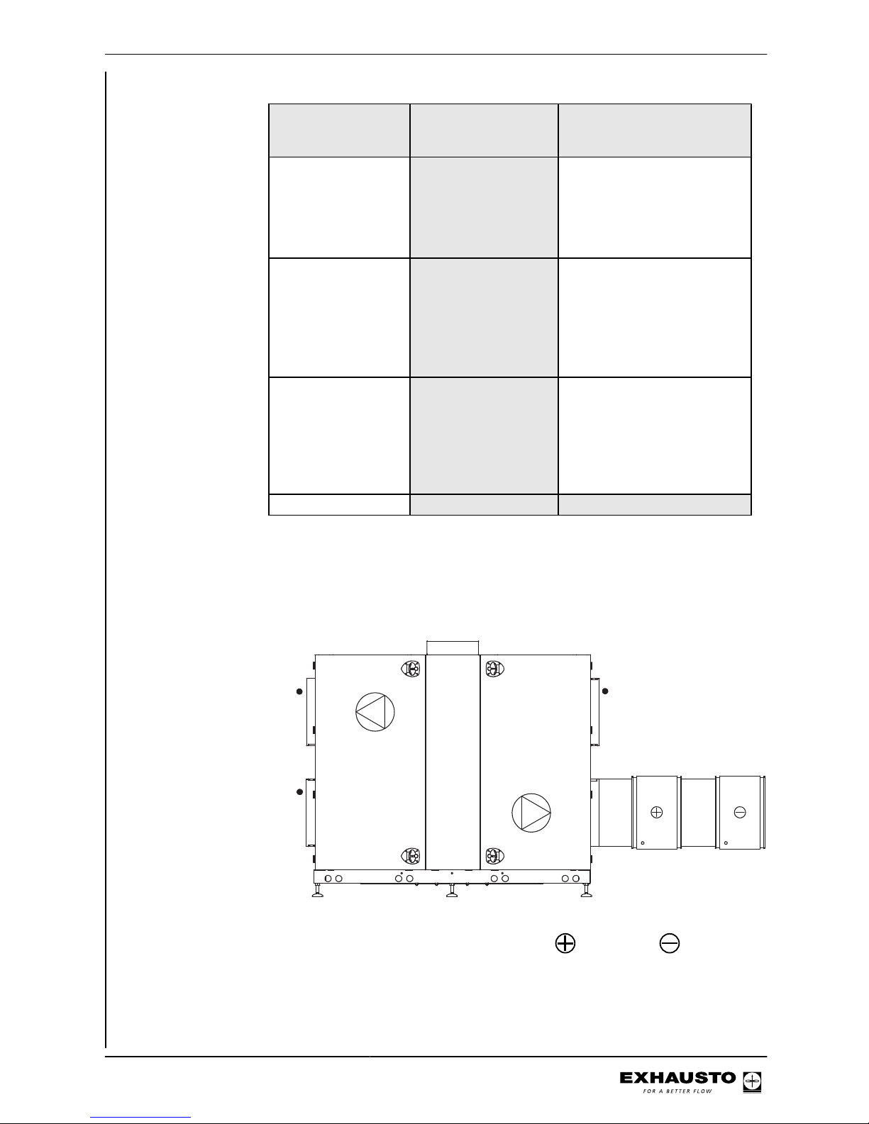
Menu 3.4 Connecting heating and cooling units
Location A heating coil and a cooling unit can be connected to the VEX. The example below
(VEX200) shows the position of the coils in relation to the VEX unit.
RD12313-02
Heating coil - Cooling unit
3003246-2014-05-21
Starting unit operation
19/100
Menu 3.5 BMS
Menu 3.5 - BMS
BMS >
Configuration >
3.5 BMS
None
Line in Menu 3.5 Comments
BMS Activating override control system BMS Op-
tions:
● None
● LON
● Modbus
● MTCP
● BACnet MSTP
● BACnetIP
Configuration Configuration of Modbus and BACnet MSTP.
BMS configuration See detailed description in the instructions for the protocols.
4.3 What is an indoor air quality level?
Example
3.1.1.1.1 Comfort
Air setpoint >
Air setpoint,cool >
Temp. setpoint >
Abs. /Rel. >
Cool rel. start >
Cool abs. start >
Heat rel. start >
Heat abs. start >
60
80
21,0
Relativ
1,0
---
-1,0
---
%
%
°c
K
K
Indoor air quality
level definition
The four indoor air quality levels - Comfort, Standby, Economy and Manual - are
defined in menus 3.1.1.1.1 to 3.1.1.1.4. Parameters such as ventilation and temperature set points and control method for a given indoor air quality level are grouped in a menu, as shown in the example above. The table below shows suggested
settings for each mode:
Indoor climate levels Energy saving People in the
room
Air replacement* Deviation from de-
sired room temperature*
(Ventilation stopped) - No No ventilation No control of room
temperature
Economy Menu
3.1.1.1.3
Large No Low Greatest tempera-
ture deviation permitted*)
Standby Menu 3.1.1.1.2 Small No Low Least temperature
deviation permitted*
Comfort Menu 3.1.1.1.1 None Yes High Precise tempera-
ture
Manual Menu 3.1.1.1.4 Dependent on set-
ting
Yes/No Adjustable Adjustable
3003246-2014-05-21
Starting unit operation
20/100

* Air replacement and temperature deviation set via the HMI panel.
The current indoor air quality level can be controlled in five ways:
● Via a weekly plan, based on the given operating requirements. Set via HMI panel.
● via an HMI panel in the room.
● via sensor(s) placed in the room or in the extract air duct (e.g. MIO-PIR, MIO-CO2,
MIO-RH, MIO-TS)
● via a PC connected to the integral web server
● via a high-level control system (e.g. BMS unit)
NB The Comfort indoor air quality level is the overriding level. The comfort level
is also activated if a mounted PIR sensor gives a signal (the unit changes from
an energy-saving indoor climate level/OFF).
Menu 1 - Selecting operating mode
1 Operating mode
Operation >
Manual
Select If
Manual The unit is intended to always operate at the same indoor air quality
level (set in Menu 3.1.1.1.4) and operation is controlled manually via
the HMI panel or the Web server
Timer The unit is controlled automatically via a fixed weekly plan
Note during commissioning
EXHAUSTO recommends that the operating mode be set to Manual during commissioning and changed to Timer operation when complete.
NB: for manual When the unit is operating in Manual air quality level, the temperature set point
(Temp. set point) and Air set point values are shown immediately in the user menu.
3.1.1.1.4 Manual
Air setpoint >
Air setpoint,cool >
Temp. setpoint >
Abs. / Rel. >
Cool rel. start >
Cool abs. start >
Heat rel. start >
Heat abs. start >
60
80
21,0
Relativ
1,0
---
-1,0
---
%
%
°c
K
K
2160°C
%
29-05-2009 14:32
Menu 3.1.1 - Operating settings - Air regulation
3.1.1 Operating settings
IAQ. levels >
Air reg. >
Temp. reg. >
Balance >
Regulators >
Supply air
1
1,0
The control method can be selected from the methods shown in the table. Note that
some of these methods require that an optional pressure sensor is fitted in one or
more ducts (MPTDUCT).
3003246-2014-05-21
Starting unit operation
21/100
Method Meth-
od no.
(1-8)
Description Following parameters are
set
Menu
Manual control
1 Constant speed
Manual control of fan speed
● Balance
3.1.1 Operating settings
IAQ. levels >
Air reg. >
Temp. reg. >
Balance >
Regulators >
Supply air
1
1,0
Airflow control
2 Constant airflow
Maintains the airflow, compensating for changes in the
ducting system, filter soiling,
etc.
● Extract airflow values
for maximum and minimum ventilation (see
capacity diagram in
VEX instructions)
● Supply air balance relative to extract air
3.1.1.4 Constant airflow
Setp. maks. >
Setp. min. >
Balance > 1,00
10000l/s
0l/s
Constant
pressure regulation of extract air
3 Constant pressure-regulated
extract air with fixed supply air
setting
Requirements:
● MPT-DUCT negative
pressure sensor in the
extract air duct. Available
as an accessory
● Extract airflow values
for maximum and minimum ventilation
● Fixed setting for supply
airflow
3.1.1.4 Constant pressure
Extract air:
Setp. max. >
Setp. min. >
Setp. >
Supply air:
1000Pa
0Pa
0l/s
5 Constant pressure-regulated
extract air with slave-controlled supply air
Requirements:
● MPT-DUCT negative
pressure sensor in the
extract air duct. Available
as an accessory
● Extract airflow values
for maximum and minimum ventilation
● Supply air balance relative to extract air
3.1.1.4 Constant pressure
Extract air:
Setp. max. >
Setp. min. >
Balance >
Supply air:
1000Pa
0Pa
1.00
Constant
pressure regulation of supply air
4 Constant pressure-regulated
supply air with fixed extract air
setting
Requirements:
● MPT-DUCT overpressure sensor in the supply
air duct. Available as an
accessory
● Supply airflow values
for maximum and minimum ventilation
● Fixed setting for extract
airflow
3.1.1.4 Constant pressure
Supply air:
Setp. max. >
Setp. min. >
Setp. >
Extract air:
1000Pa
0Pa
0l/s
3003246-2014-05-21
Starting unit operation
22/100
Method Meth-
od no.
(1-8)
Description Following parameters are
set
Menu
6 Constant pressure regulated
supply air with slave-controlled extract air
Requirements:
● MPT-DUCT overpressure sensor in the supply
air duct. Available as an
accessory
● Supply airflow values
for maximum and minimum ventilation
● Extract air balance relative to supply air
3.1.1.4 Constant pressure
Supply air:
Setp. max. >
Setp. min. >
Balance >
Extract air:
1000Pa
0Pa
1.00
Constant
pressure regulation of both
extract air and
supply air
7 Constant pressure regulation
of both extract air and supply
air
Requirements:
● MPT-DUCT negative
pressure sensor in the
extract air duct. Available
as an accessory
● MPT-DUCT overpressure sensor in the supply
air duct. Available as an
accessory
● Extract airflow values
for maximum and minimum ventilation
● Supply airflow values
for maximum and minimum ventilation
3.1.1.4 Constant pressure
Extract air:
Setp. max. >
Setp. min. >
Setp. max. >
Setp. min. >
Supply air:
1000Pa
0Pa
1000Pa
0Pa
External control of fan
speeds
8 External control of both ex-
tract air and supply air
Requirements:
● Two MIO modules to convert 0–10 V to Modbus
● FC max/FC min: Control signal range for external control (e.g. 2-10
V signal)
● Control signal to override external damper* in
the event of, e.g. nighttime cooling or fire
*or other third-party accessory, which is controlled by
external control
3.1.1.4 AUX
Type >
BFO
BMS
101None
Menu 3.1.1 - Operating settings Balance
Definition Balance is the required ratio between the supply and extract airflows. The balance
can only be maintained within certain operating ranges, limited by factors such as:
● Duct characteristics
● Minimum fan rpm
● Minimum airflow required
● Maximum airflow required
3003246-2014-05-21
Starting unit operation
23/100

Example of balance The examples show a unit with manual fan control and balances of 0.80 and 1.20
respectively.
Range The required airflow is
A outside the unit’s normal operating range
B balanced
C unbalanced
NB Less than 1 = less supply air - Greater than 1 = less extract air
Note for methods 3,
4, 7 and 8
Balance is not active for air regulation methods 3, 4, 7 and 8.
Menu 3.1.1.5 Regulators
3.1.1.5 Regulators
Room temperature >
Supply air temp. >
Supply airflow >
Extract airflow >
Supply pressure >
Extract pressure >
Heat retention >
3003246-2014-05-21
Starting unit operation
24/100
Kp and Ti settings should only be changed by persons trained in commissioning ventilation systems.
If the following is selected Permitted operations
Technician mode (code 1111) Read the settings for the various
regulators
Specialist mode (code 3142) Set Kp and Ti for the various reg-
ulators
Menus 3.1.1.1.1 to 3.1.1.1.4 Configuring the selected indoor air quality levels
The menus for the four indoor air quality levels contain the same menu items:
3.1.1.1.1 Comfort
Air setpoint >
Air setpoint,cool >
Temp. setpoint >
Abs. /Rel. >
Cool rel. start >
Cool abs. start >
Heat rel. start >
Heat abs. start >
60
80
21,0
Relativ
1,0
---
-1,0
---
%
%
°c
K
K
3.1.1.1.2 Standby
Air setpoint >
Air setpoint,cool >
Temp. setpoint >
Abs. /Rel. >
Cool rel. start >
Cool abs. start >
Heat rel. start >
Heat abs. start >
60
80
21,0
Relativ
1,0
---
-1,0
---
%
%
°c
K
K
3.1.1.1.3 Economy
Air setpoint >
Air setpoint,cool >
Temp. setpoint >
Abs. / Rel. >
Cool rel. start >
Cool abs. start >
Heat rel. start >
Heat abs. start >
60
80
21,0
Relativ
1,0
---
-1,0
---
%
%
°c
K
K
3.1.1.1.4 Manual
Air setpoint >
Air setpoint,cool >
Temp. setpoint >
Abs. / Rel. >
Cool rel. start >
Cool abs. start >
Heat rel. start >
Heat abs. start >
60
80
21,0
Relativ
1,0
---
-1,0
---
%
%
°c
K
K
Menu 3.1.1.1.x - Air set point
Definition Used to set the desired ventilation level for the given indoor air quality level, from 0
to 100%. Press "OK" to end.
Menu 3.1.7 - limits
menu
See the range limits for fan output in Menu 3.1.7 in the HMI panel.
Menu 3.1.1.1.x - Temperature set point
Definition The required supply air or room temperature is set here. If "Absolute" indoor air
quality level is selected (see next section), then the temperature set point can be
selected (with 0.5 degree difference) within the configured "Cooling absolute start"
and "Heating absolute start" ranges (for more details see relevant section).
Menu 3.1.8 - limits
menu
See the range limits for supply air temperature and room temperature in Menu 3.1.8
in the HMI panel.
Menu 3.1.1.1.x - Absolute / Relative temperature
Definition Used to select supply air or room temperature in relation to either absolute or relative
temperature.
Absolute - Specify start temperature for heating coil or cooling unit.
Relative - Permitted temperature changes relative to the heating coil or cooling unit
start temperature. See how the temperature variation follows when the set point is
altered (diagram below, dotted lines).
3003246-2014-05-21
Starting unit operation
25/100
Menu 3.1.1.1.x - Cooling relative start
Definition This value determines when cooling must start in relation to the relative tempera-
ture. Low value = narrow temperature regulation range, leading to a comfortable
indoor climate. High value = wider temperature regulation range, which provides
cooling energy savings. Lower and upper limits are shown in the display.
Example If the required room temperature is 21°C, and Cooling Rel. start in the indoor air
quality level menu is set to 3K, the cooling unit will begin to operate on a warm day
when the temperature exceeds 21°C + 3K = 24°C.
Menu 3.1.1.1.x - Heating relative start
Definition This value determines when the heating coil must start in relation to the relative
temperature. Low value = narrow temperature regulation range, leading to a comfortable indoor climate. High value = wider temperature regulation range, which
saves energy because of lower heating requirements. Lower and upper limits are
shown in the display.
Example If the required room temperature is 21°C, and Heating Rel. start in the indoor air
quality level menu is set to -3K, the heating coil will begin to operate on a cold day
when the temperature falls below 18°C (21°C - 3K).
Menu 3.1.1.1.x - Cooling absolute start
Definition This value determines when cooling must start in relation to the absolute tempera-
ture. Lower and upper limits are shown in the display.
3003246-2014-05-21
Starting unit operation
26/100
Example If Cooling abs. start is set to 24°C, the cooling unit will first start to operate when
the temperature exceeds 24°C, even though the daily user has set the required
room temperature to 21°C.
Menu 3.1.1.1.x - Heating absolute start
Definition This value determines when heating must start in relation to the absolute temper-
ature. Lower and upper limits are shown in the display.
Example If Heating abs. start is set to 18°C, the heating coil will not start to operate until the
temperature falls below 18°C, even though the daily user has set the required room
temperature to 21°C.
Generally on temperature regulation
● Start by setting the max. and min. limits
● Set the temperature setpoint
● For other regulators, first set the max./min. and then the setpoint
3.1.1 Operating settings
IAQ. levels >
Air reg. >
Temp. reg. >
Balance >
Regulators >
Supply air
1
1,0
If temperature regulation is changed from Supply Air to Room, the functions on the
next pages will be enabled, and invalid values will be adjusted to valid values. If
temperature regulation is changed from Room to Supply Air, nothing will happen,
as the limits for Room are always within the limits for Supply Air.
Menu 3.1.8 - Temperature limits
Grænser tillufttemp.
Minimum >
Maksimum >
Grænser rumtemp.
Minimum >
Maksimum >
Maksimum ∆T >
10.0
35.0
10.0
35.0
10.0
°C
°C
°C
°C
K
3.1.8 Temperaturgrænser
Limits, supply air
temperature
3003246-2014-05-21
Starting unit operation
27/100
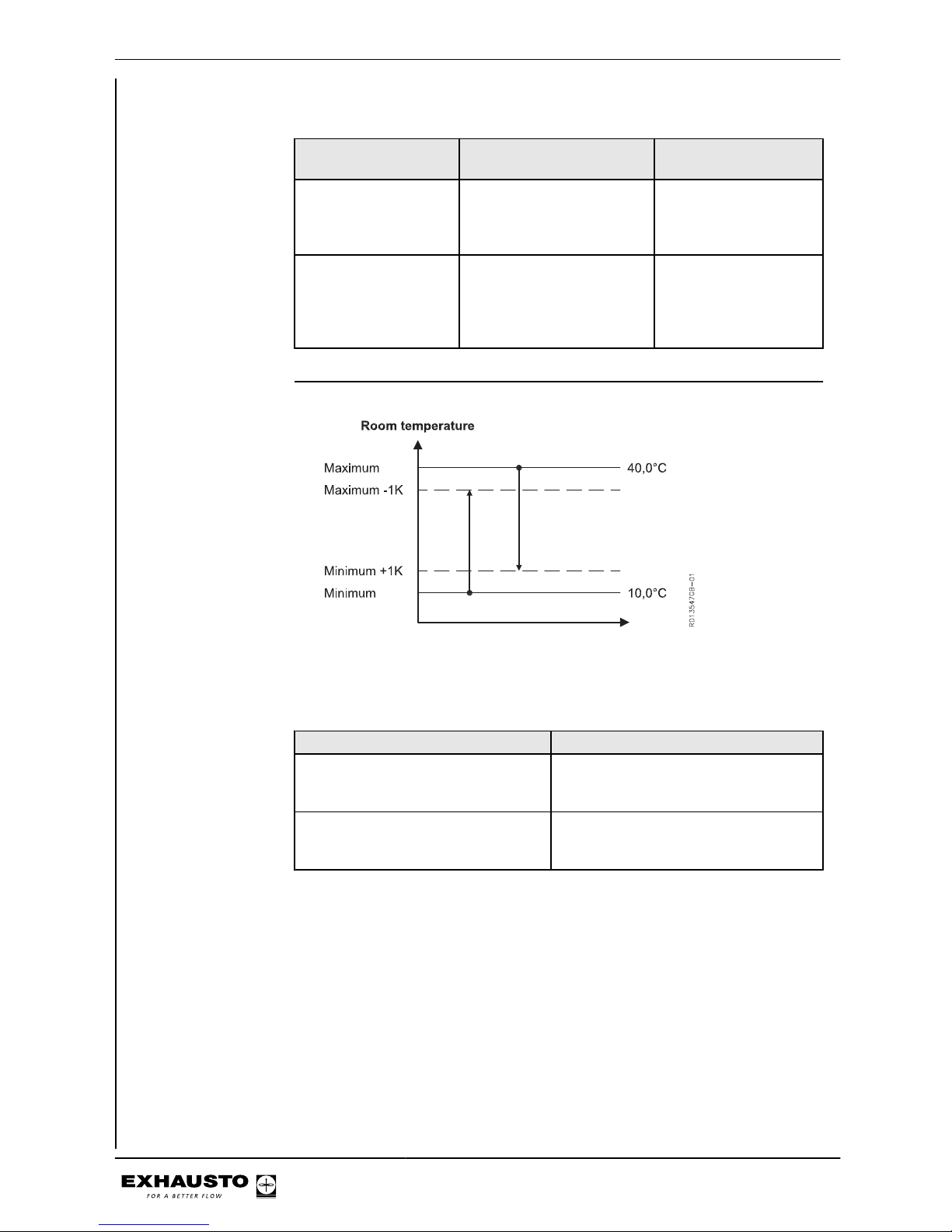
NB Max. and Min. may never be set closer to each other than 1K.
If the following is selected
temperature will be controlled by...
NB
supply air regulation supply air temperature Supply air temperature
will never be higher than
"Maximum" or lower
than "Minimum".
room temperature regulation
extract air temperature or
TSROOM
However, supply air
temperature will never
be higher than "Maximum" or lower than
"Minimum".
Limits, room temperature
NB Max. and Min. may never be set closer to each other than 1K.
If the following will be adjusted....
Supply air temp. maximum is set lower
than the room temp. maximum.
The room temp. maximum is automatically reduced to the same value as the
supply air temp. maximum.
The supply air temp. minimum is set
higher than the room temp. minimum.
The room temp. minimum is automatically increased to the same value as the
supply air temp. minimum.
3003246-2014-05-21
Starting unit operation
28/100
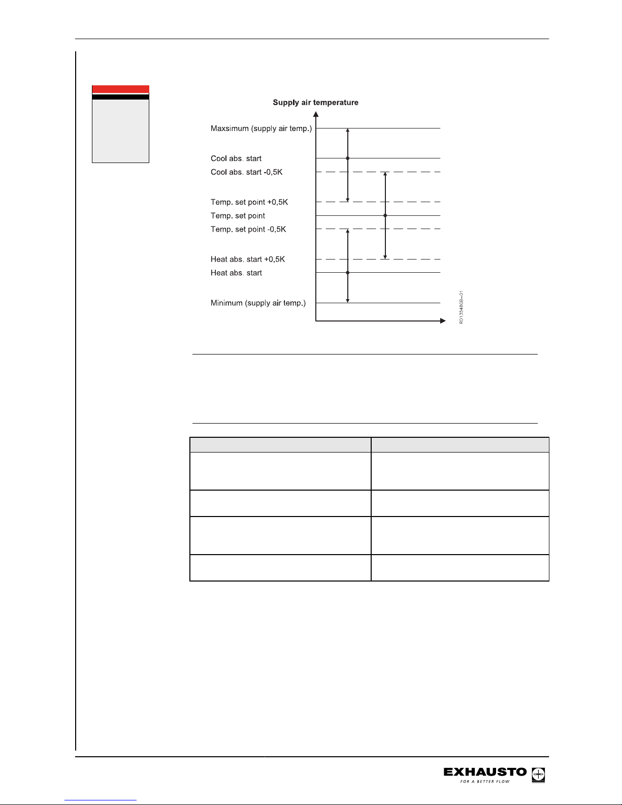
Menu 3.1.1.1.x - Supply air regulation, absolute
Air setpoint >
Air setpoint,cool
Temp. setpoint >
Abs. / Rel. >
Cool rel. start >
Cool abs. start >
Heat rel. start >
Heat abs. start >
3.1.1.1.x xxxxxxx
60
80
21,0
Absolute
---
26,0
---
21,0
%
°c
°c
°c
NB Temp. setpoint can never be set closer to Heating abs. start or Cooling abs. start
than 0.5K.
Heating abs. start and Cooling abs. start can never be set closer to each other than
1K.
If the following will be adjusted....
Maximum supply air temp. is set to a value lower than Cooling abs. start
Cooling abs. start will automatically reduce to the same value as Maximum
supply air temp.
Cooling abs. start is set to a value lower
than (Temp. setpoint + 0.5K)
Temp. setpoint will automatically reduce
to (Cooling abs. start - 0.5K).
Minimum supply air temp. is set to a value
higher than Heating abs. start
Heating abs. start will automatically rise
to the same value as Minimum supply air
temp.
Heating abs. start is set to a value higher
than (Temp. setpoint - 0.5K)
Temp. setpoint will automatically rise to
(Heating abs. start + 0.5K).
3003246-2014-05-21
Starting unit operation
29/100
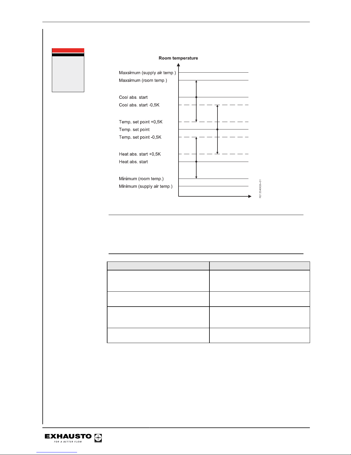
Menu 3.1.1.1.x - Room temperature regulation, absolute
Air setpoint >
Air setpoint,cool
Temp. setpoint >
Abs. / Rel. >
Cool rel. start >
Cool abs. start >
Heat rel. start >
Heat abs. start >
3.1.1.1.x xxxxxxx
60
80
21,0
Absolute
---
26,0
---
21,0
%
°c
°c
°c
NB Temp. setpoint can never be set closer to Heating abs. start or Cooling abs. start
than 0.5K.
Heating abs. start and Cooling abs. start can never be set closer to each other than
1K.
If the following will be adjusted....
Maximum room temp. is set to a value
lower than Cooling abs. start
Cooling abs. start will automatically reduce to the same value as Maximum
room temp.
Cooling abs. start is set to a value lower
than (Temp. setpoint + 0.5K)
Temp. setpoint will automatically reduce
to (Cooling abs. start - 0.5K).
Minimum room temp. is set to a value
higher than Heating abs. start
Heating abs. start will automatically rise
to the same value as Minimum room
temp.
Heating abs. start is set to a value higher
than (Temp. setpoint - 0.5K)
Temp. setpoint will automatically rise to
(Heating abs. start + 0.5K).
3003246-2014-05-21
Starting unit operation
30/100
 Loading...