

Exhausto EFC 25 Installation & Operating Instructions Manual
EXHAUSTO 3001736-2004-01-21.fm Installation & operating instructions
GB
EFC 25
Odensevej 76 · DK-5550 Langeskov
EXHAUSTO A/S
Tlf. +45 65 66 12 34 · Fax +45 65 66 11 10
exhausto@exhausto.dk · www.exhausto.com
EXHAUSTO 3001736-2004-01-21.fm 2/12
1. Product information
1.1 EFC 25 Control System for EXHAUSTO Chimney Fans................................... 3
1.2 Description...........................................................................................................4
2. Installation
2.1 Installation of control panel and external IR-sensor........................................ 5
2.2 Power supply ....................................................................................................... 5
2.3 Standard installation ........................................................................................... 6
2.4 Installation with external start............................................................................ 7
3. Commissioning
3.1 Service mode ....................................................................................................... 8
3.2 Setting of potentiometer .....................................................................................9
3.3 Adjustment of pressure differential switch (PDS) ............................................9
3.4 Test of commissioning........................................................................................ 9
3.5 Complete the commissioning card....................................................................9
4. Daily use
5. Fault finding
6. Technical data
Symbol legend The following terms are used throughout this manual to bring attention to the presence
of potential hazards or important information concerning the product:
DANGER: Indicates an imminently hazardous situation which, if not avoided, will result in death, serious injury or substantial property damage.
CAUTION: Indicates an imminently hazardous situation which, if not avoided, may result in personal injury or property damage.
How to use this
The manual concerns EXHAUSTO fireplace control EFC 25 and a remote control.
manual
Safety for personnel and property as well as correct operation of the chimney fan are
obtained by following the directions of this manual.
EXHAUSTO disclaims all responsibility for damages caused by misapplication of this
product in contravention of directions and instructions in this manual.

EXHAUSTO 3001736-2004-01-21.fm 3/12
1. Product information
1.1 EFC 25 Control System for EXHAUSTO Chimney Fans
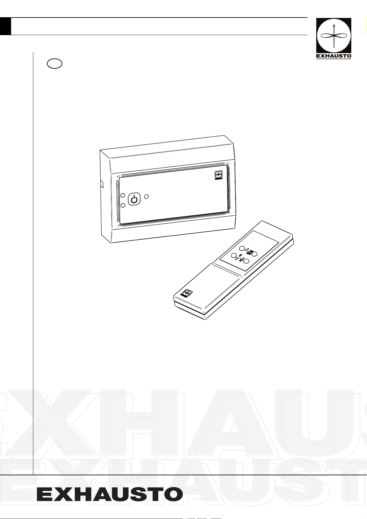
Applications The EXHAUSTO fireplace control EFC 25 (Fig. 1) has been developed for use with gas
fire control units which have flame detection and automatic ignition, and in connection
with the installation of EXHAUSTO chimney fans.
The control system supervises the fail-safe function. In case of insufficient chimney
draught, the EFC 25 will shut down the fireplace.
The control system is developed to meet BS 5440: Part 1(2000), BS 6644(1991), Gas
Appliance Directive 90/396/EEC, EN 298(1993) and other relevant European standards.
Functions By activating the EFC 25, the chimney fan will immediately start up on full speed. When
the fail-safe supervision confirms sufficient chimney draught, the fireplace will be lit and
the fan speed will adjust to the pre-set value corresponding to the appliance operating
normally, (Fig. 1-J).
The control has a step-up function and a 15-second built-in delay function to avoid
nuisance cut-outs.
By using the remote control (Fig. 2) it is possible to switch between high and low fire.
When EFC 25 is turned off, the chimney fan stops. It is possible to pre-set a run-on time
period of 3 minutes, (Fig. 1-I).
The EFC 25 and RSVG can also be used for venting purposes.
Fail-safe settings. The fail-safe settings can be set by dipswitches (Fig. 1-I) according to local laws and
standards.
• RESET after fail-safe lock-out (manual/automatic).
EXHAUSTO 3001736-2004-01-21.fm 4/12
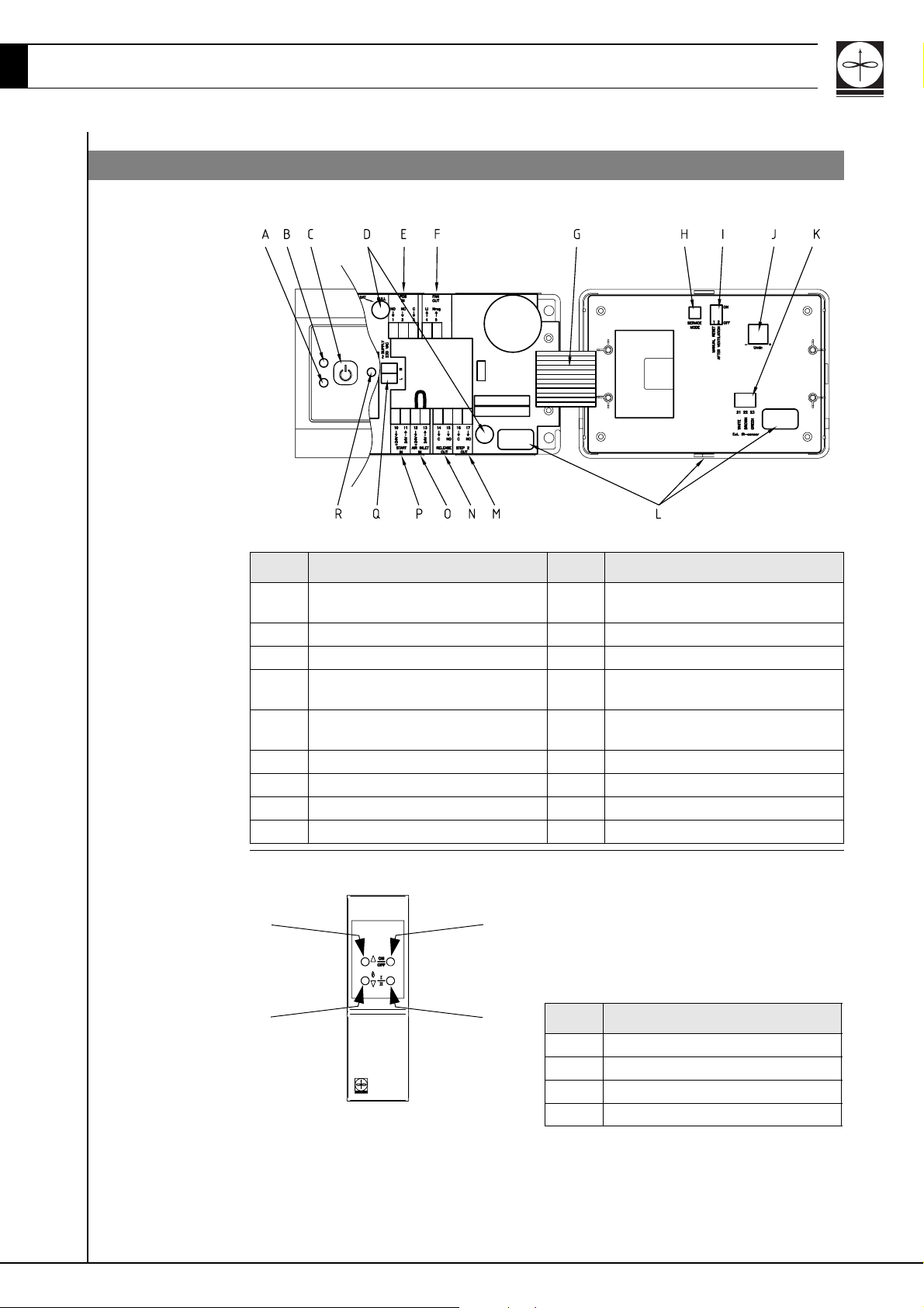
1.2 Description
EFC 25 control
Fig. 1
Remote control
Pos. Description Pos. Description
A Alarm LED J Potentiometer for adjusting the fan
speed
B Operating LED K Socket for external IR-receiver
C ON/OFF button L Product ID
D Fuses T3,15A 230V(spare fuse
included in control box)
E PDS pressure differential switch
terminals
F Terminals for chimney fan O Terminals for fresh air inlet
G Connection cable P Terminals for external start
H Service mode button Q Terminals for power supply
I Dipswitches R Internal IR-receiver
A
B
M Terminals for Step 2
N Terminals for start signal to fireplace
control
D
Fig. 2
C
Pos. Description
A Fan speed up.
B ON/OFF button
CStep I/II button
D Fan speed down or Burner start
 Loading...