

Exhausto BESF Series, BESF 146, BESF 160, BESF 180 Installation & Operating Manual

Installation & Operating Manual
USA
CAN
3001806 03.02
BESF
Box Ventilator
READ AND SAVE
THESE INSTRUCTIONS
1200 Northmeadow Parkway, STE 180 • Roswell, GA 30076
(770) 587-3238 (800) 255-2923 Fax (770) 587-4731
info@exhausto.com us.exhausto.com
1. Product Information
1.1 Function........................................................................................................................... 3
1.2 Components .................................................................................................................... 3
1.3 Shipping........................................................................................................................... 4
2. Specications
2.1 Dimensions & Capacities................................................................................................. 5
3. Installation
3.1 Positioning ....................................................................................................................... 6
3.2 Floor or Roof Mounting.................................................................................................... 6
3.3 Ceiling Mounting.............................................................................................................. 7
4. Wiring
4.1 Electrical Requirements................................................................................................... 8
4.2 Wiring Diagram — BESF 146-180................................................................................... 8
5. Duct Connection
5.1 Connection to Duct .......................................................................................................... 9
6. Service & Maintenance
6.1 Cleaning Intervals.......................................................................................................... 10
6.2 Cleaning ........................................................................................................................ 10
6.3 Service........................................................................................................................... 10
7. Troubleshooting
.............................................................................................................................................11
8. Spare Parts
8.1 Parts Ordering ............................................................................................................... 12
9. Warranty
9.1 Warranty ........................................................................................................................ 13
9.2 Warranty Disclaimer ...................................................................................................... 13
Symbol Legend:
The following terms are used throughout this manual to bring attention
to the presence of potential hazards or to important information
concerning the product.
Danger: Indicates an imminent hazardous situation which,
if not avoided, will result in death, serious injury or
substantial property damage.
Caution: Indicates an imminent hazardous situation
which, if not avoided, may result in personal injury or
property damage.
TO REDUCE THE RISK OF FIRE, ELECTRICAL SHOCK OR INJURY TO PERSONS,
OBSERVE THE FOLLOWING:
1. Use this unit in the manner intended by the manufacturer. If
you have questions, contact the manufacturer at the address or
telephone number listed on the front of the manual.
2. Before servicing or cleaning the unit, switch off at service panel
and lock service panel to prevent power from being switched on
accidentally.
3. Installation work and electrical wiring must be done by a qualied
person(s) in accordance with applicable codes and standards.
4. Follow the appliance manufacturer’s guidelines and safety
standards such as those published by the National Fire Protection
Associations (NFPA), and the American Society for Heating,
Refrigeration and Air Conditioning Engineers (ASHRAE), and the
local code authorities.
5. This unit must be grounded.
How to use this manual
This installation manual does not contain any system design
documentation. System design documentation is available from any
authorized EXHAUSTO representative.
Accessories, fans and variable frequency drives are not covered by
this manual. Please refer to these component’s individual manuals.
2/16
1. Product Information
1.1 Function
Use EXHAUSTO Model BESF is a box ventilator that can be used for the movement of air in exhaust and air
supply systems where no explosive gases are present. The ventilator cannot be used for transport of
large particles. It is designed to provide a high capacity at a high static pressure.
The ventilator can be installed indoors as well as outdoors. No special treatment or preparation is
required for weather proong.
Suitable uses include, but are not limited to: comfort ventilation, residential kitchen ventilation,
exhaust and air supply.
The exhaust temperature must be above 10°F(-12°C) but should not exceed 175°F(80°C). The ambient
temperature must be within -20°F(-30°C) and 105°F(40°C).
Construction The ventilator housing is made of galvanized steel and insulated with ber insulation. The
collars are tted with silicone seals to assure a tight assembly. The motor is a direct drive, variable
speed class B insulated type. It has permanently lubricated, sealed ball bearings and is maintenance
free.
Listings EXHAUSTO Model BESF is tested and listed to UL 705, Standard for Power Ventilators.
The BESF can be used as a component in a MCAS, Modulating Combustion Air System. The listings of
this system incorporates the BESF Box Ventilator.
Do not use with explosive gases. Do not use for transport of large particles.
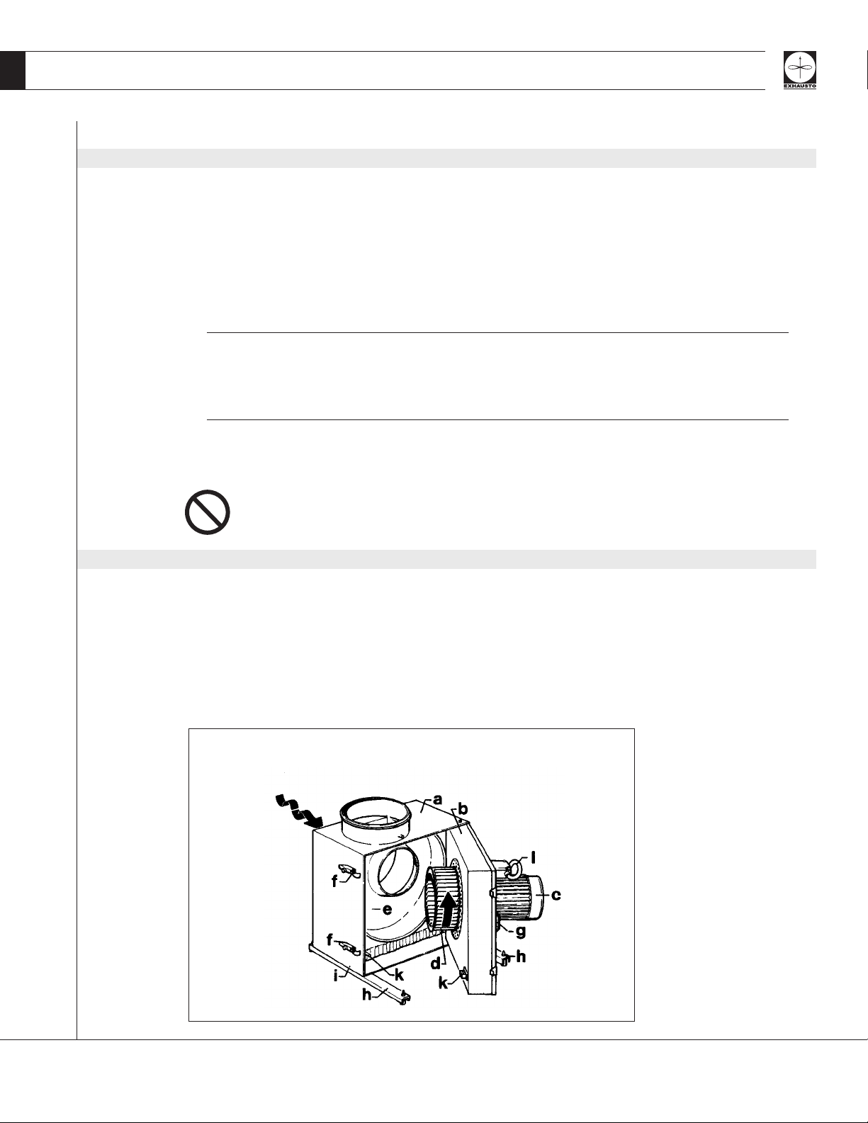
1.2 Components
The box ventilator consists of the following components:
a. Housing f. Locking hinge
b. Access door g. Door handle
c. Motor h. Support legs with vibration dampers (2)
d. Centrifugal impeller i. Sheet metal screws (4)
e. Ventilator housing k. Door switch (optional)
Fig. 1
+10°F - +175°F
(-120°C - +80°C)
-20°F - +105°F
(-30°C - +40°C)
3/16

1.3 Shipping
Protection The ventilator is protected by a corrugated box. Do not place other products or items on top of the box.
After unpacking, the product must be handled in a way to prevent damaging the collars and the
ventilator housing.
Fig. 2
Never operate the ventilator with the access door open!
To open access door loosen screws on latch handles and raise handles.
Standard The ventilator is shipped with motor installed on the access door. If other components are shipped,
Packing these will appear on the shipment packing list.
4/16
2. Specications
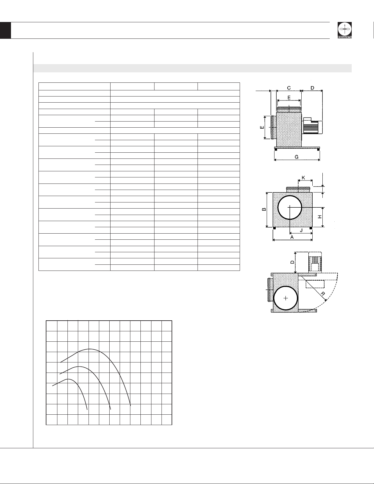
2.1 Dimensions & Capacities
Model BESF 146 BESF 160 BESF 180
Fan Type Centrifugal Impeller (F-Wheel)
Motor Type TEFC
Voltage V AC 1x120
Amperage Amps 1.2 2.9 5.8
Motor Output HP 0.1 0.2 0.5
kW 0.08 0.16 0.35
RPM 1600
Weight lbs 28 38 60
kg 13 17 27
Duct Connection E in 7 8 8
mm 177 200 200
Dimensions A in 13.60 14.57 16.15
mm 345 370 410
B in 11.62 12.60 13.98
mm 295 320 355
C in 7.88 9.26 9.26
mm 200 235 235
D in 4.33 5.52 7.68
mm 110 140 195
G in 13.78 15.75 15.75
mm 350 400 400
H in 6.50 7.10 7.88
mm 165 180 200
J in 7.88 8.27 9.26
mm 200 210 235
K in 4.33 5.12 5.12
mm 110 130 130
R in 13.60 14.57 16.15
mm 345 370 410
Capacity Chart
5/16
 Loading...