

Exhausto BESF, BESF/7 Series, BESF180-4-1EC, BESF146-4-1, BESF200-4-1EC Series Manual
...
3004349_2017_08_03.fm
BESF
BESF/7
1/64
3004349_2017_08_03.fm
GB - BESF – Product information
1.1 Design.......................................................................................................... 4
1.2 Fitting.......................................................................................................... 6
1.2.1 Fitting indoors ...............................................................................................6
1.2.2 Fitting outdoors (OD)..................................................................................... 7
1.2.3 Fitting the mounting bars............................................................................... 7
1.3 Wiring........................................................................................................... 8
1.3.1 Ventilator without EC control.........................................................................8
1.3.2 Ventilator with EC control..............................................................................9
1.3.3 Fault finding: phase-one EC controls ..........................................................12
1.4 Connecting to duct system........................................................................ 13
1.5 Service and cleaning .................................................................................. 14
1.6 Environmental declaration......................................................................... 14
DK - BESF - Produktvejledning
1.1 Opbygning................................................................................................... 16
1.2 Montage ...................................................................................................... 18
1.2.1 Indendørs placering ....................................................................................18
1.2.2 Udendørs placering (OD) ............................................................................19
1.2.3 Montage af bæreskinner ............................................................................. 19
1.3 El-tilslutning ................................................................................................ 20
1.3.1 Ventilatorer uden EC-styring .......................................................................20
1.3.2 Ventilatorer med EC-styring ........................................................................21
1.3.3 Fejlfinding for 1-fasede EC-styringer...........................................................24
1.4 Kanaltilslutning........................................................................................... 25
1.5 Service og rengøring.................................................................................. 26
1.6 Miljødeklaration........................................................................................... 26
DE - BESF - Betriebsanleitung
1.1 Aufbau.......................................................................................................... 28
1.2 Montage ...................................................................................................... 30
1.2.1 Aufstellung in Innenräumen ........................................................................30
1.2.2 Aufstellung im Freien (OD).......................................................................... 31
1.2.3 Montage von Tragschienen.........................................................................31
1.3 Elektrischer Anschluss .............................................................................. 32
1.3.1 Ventilatoren ohne EC-Automatik .................................................................32
1.3.2 Ventilatoren mit EC-Automatik ....................................................................33
1.3.3 Fehlersuche bei einphasigen EC-Automatik ............................................... 36
1.4 Kanalanschluss........................................................................................... 37
1.5 Wartung und Reinigung ............................................................................. 38
1.6 Umweltdeklaration...................................................................................... 39
NO - BESF - Produktveiledning
1.1 Oppbygning................................................................................................. 40
1.2 Montering.................................................................................................... 42
1.2.1 Innendørs plassering ..................................................................................42
1.2.2 Utendørs plassering (OD) ........................................................................... 43
1.2.3 Montering av bæreskinner...........................................................................43
1.3 Elektrisk tilkobling...................................................................................... 44
1.3.1 Vifter uten EC-styring .................................................................................. 44
1.3.2 Vifter med EC-styring .................................................................................. 45
1.3.3 Feilsøking for enfasede EC-styringer ..........................................................48
1.4 Kanaltilkobling ............................................................................................ 49
1.5 Service og rengjøring................................................................................. 50
1.6 Miljødeklarasjon.......................................................................................... 50
2/64
3004349_2017_08_03.fm
SE – BESF – Produkthandbok
1.1 Konstruktion................................................................................................ 52
1.2 Montering.................................................................................................... 54
1.2.1 Inomhusmontering ......................................................................................54
1.2.2 Placering utomhus (OD)..............................................................................55
1.2.3 Montering av bärskenor...............................................................................55
1.3 Elanslutning ................................................................................................ 56
1.3.1 Fläktar utan EC-styrning..............................................................................56
1.3.2 Fläktar med EC-styrning..............................................................................57
1.3.3 Felsökning för 1-fas EC-styrningar..............................................................60
1.4 Kanalanslutning.......................................................................................... 61
1.5 Service och rengöring................................................................................ 62
1.6 Miljödeklaration..................................................................................................62
3/64

3004349_2017_08_03.fm GB - BESF – Product information
Fig. 1
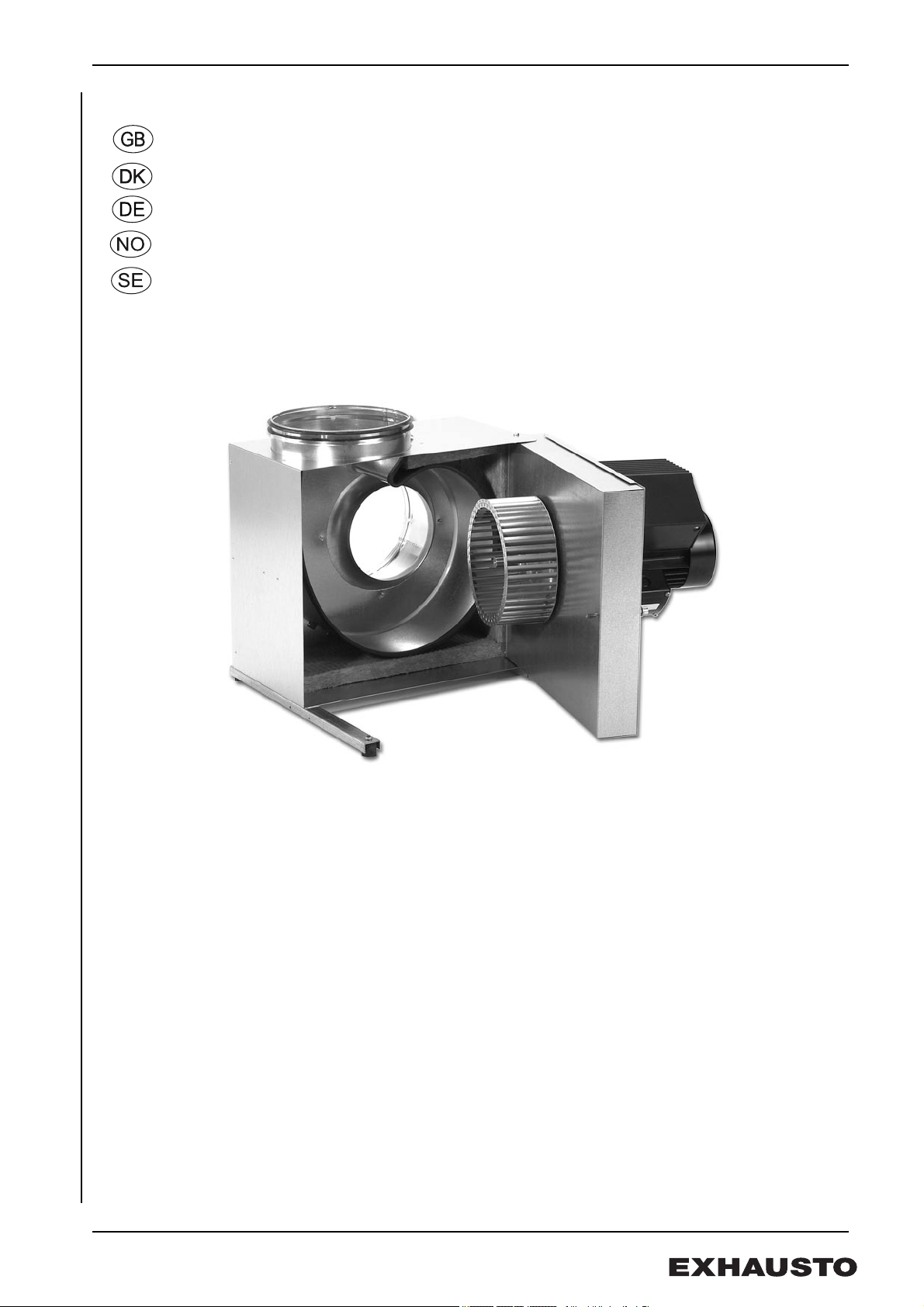
1. GB - BESF – Product information
EXHAUSTO BESF box ventilators are used in air supply and extraction systems.
The ventilator is not to be used for the transportation of solid particles,
nor in areas where there is a risk of explosive gases.
The ventilator must not be started with the service door open.
1.1 Design
Description BESF is a low-noise centrifugal ventilator with complete insulation and an F-impeller:
• BESF146-4-1
• BESF160-4-1
• BESF160-2-1EC
• BESF180-4-1EC
• BESF200-4-1EC
• BESF225-4-1EC
• BESF250-4-1EC
• BESF280-4-3EC
The ventilator has an internal insulated laminar housing and an external cabinet made
of sheet aluminium.
Temperature
limits
Type
BESF –12ºC 60ºC –30ºC 40ºC
Spigot size The ventilator’s connection size conforms to Eurovent.
BESF 146 160/180 200/225 250/280
D (mm)
Transport The ventilator is delivered packaged and can be
transported on a hand trolley. Care must be
taken to avoid any damage to the cabinet and
spigots when the ventilator has been removed
from its packaging.
Temperature - medium
Min. Max. Min. Max.
Ø 160 Ø 200 Ø 250 Ø 315
Temperature – ambient,
running
Size and weight.
BESF 146 160 180 200 225 250 280
Weight kg
13 17 22 (EC) 23 27 32 41 49
4/64
3004349_2017_08_03.fm GB - BESF – Product information
RD13285-01
i
b
a
c
d
e
f
g
h
M
a
x
.
6
0
°
C
M
a
x
.
4
0
°
C
j
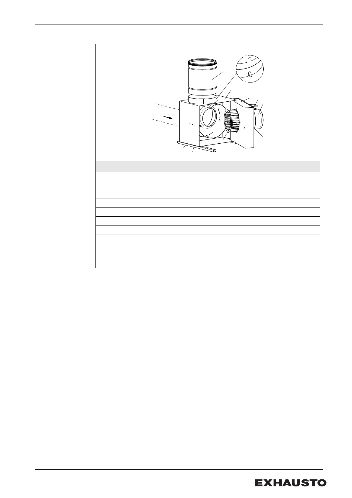
Fig. 2
Main parts
Pos. Part
a Cabinet
b Service door
c Motor
d Centrifugal impeller
e Ventilator housing
f Locking screws (supplied with screwdriver)
g Mounting bars with vibration dampers
h Self-tapping screws
i OSGR coupling (accessory). When fitting the OGSR, the slit must always be
opposite the rivet, so that the guide plates are turned correctly.
j EC control/terminal box
5/64

3004349_2017_08_03.fm GB - BESF – Product information
Fig. 3
RD13307-01
D
D
Fig. 4
1.2 Fitting
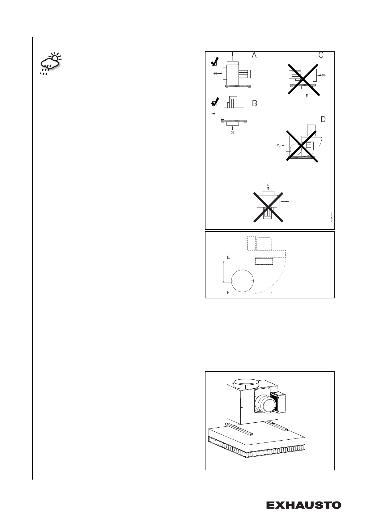
1.2.1 Fitting indoors
There are various ways of fitting the
ventilator indoors (Fig. 3).
If the ventilator is to run intermittently,
there is a risk of condensation in the
motor. Therefore, use mounting
method A or B only.
Service access Wherever the ventilator is fitted, there
should be space enough to be able to
open the service door to an angle of
approx. 90°.
Warning! The motor must never be placed vertically under the cabinet, and the
motor and EC-controls must never be covered or they will overheat.
6/64
3004349_2017_08_03.fm GB - BESF – Product information
Fig. 5
Fig. 6
RD13307-01
D
D
RD13309-01
Fig. 7
1.2.2 Fitting outdoors (OD)
Outdoor fitting requires special
attention as water must be
prevented from penetrating the
construction. This must be done
through extra jointing and
screening.
Motor and EC motor control, if any,
are prepared for outdoor fitting for
pos. A or B. (Fig. 5)
Service access Wherever the ventilator is fitted, there
should be enough space to be able to
open the service door to an angle of
approx. 90° and to access the locking
screws.(Fig. 6)
1.2.3 Fitting the mounting bars
• Mounting should be done on a stable vibration-resistant base, to minimise any
vibration that might be caused by the ventilator. A cement slab placed on a
wooden base construction is recommended.
• Fit the mounting bars on the cabinet with the supplied fitting screws. The cabinet
has holes already bored for fitting method A.
• Place the ventilator on the supporting base. Do not fasten the ventilator to the
base.(Fig. 7)
7/64
3004349_2017_08_03.fm GB - BESF – Product information
RD12102-01
Fig. 8
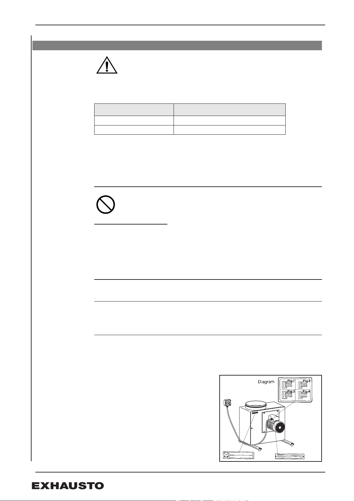
1.3 Wiring
General
The wiring must only be done by a qualified electrician.
The fan and motor specifications are listed on the type-plates.
Max. fuse rating = 13 Amp.
If the fuse is a ...it must have the characteristic
melting fuse gG or gM.
control fuse B or C, and comply with IEC 90947-2. -
Max. short circuit current is 10 kA
At start-up and during the initial adjustment of the fan, it is important to control the
direction of rotation of the motor and to check the motor current does not exceed the
manufacturer’s recommended operating current for the motor (to avoid damaging the
motor).
Isolation switch EXHAUSTO A/S would like to draw attention to the fact that, in
accordance with the EU's Machine Directive (appendix 1)
all fan
systems shall include a isolation switch.
The isolation switch must ...
• be lockable or positioned in plain sight in the immediate vicinity of the fan
• be able to disconnect all poles from the supply voltage
— contact distance of at least 3 mm in each pole
• Set up as isolation switch in accordance with standard IEC 60947-1 or
IEC 60947-3.
The isolation switch is not supplied by EXHAUSTO.
Lightning
conductor
Any lightning conductor connected to the fan must be in accordance with applicable
regulations and legislation.
1.3.1 Ventilator without EC control
Wiring Wiring should be done as stipulated in the electrical drawing in the door of the motor’s
terminal box (Fig. 8).
BESF146-4-1
BESF160-4-1
All one-phase ventilators are voltage regulated.
The motor is fitted with a thermal cut-out. The thermal cut-out is factory-fitted, wired in
series to the motor’s power circuit (please see wiring diagram in the terminal box, Fig. 1).
Use the wiring diagram (Fig. 2) if a manual reset is required after a thermal cut-out,
where the thermal cut-out is used as a contact in the control circuit.
The motor has overload protection.
8/64
3004349_2017_08_03.fm GB - BESF – Product information
Fig. 9
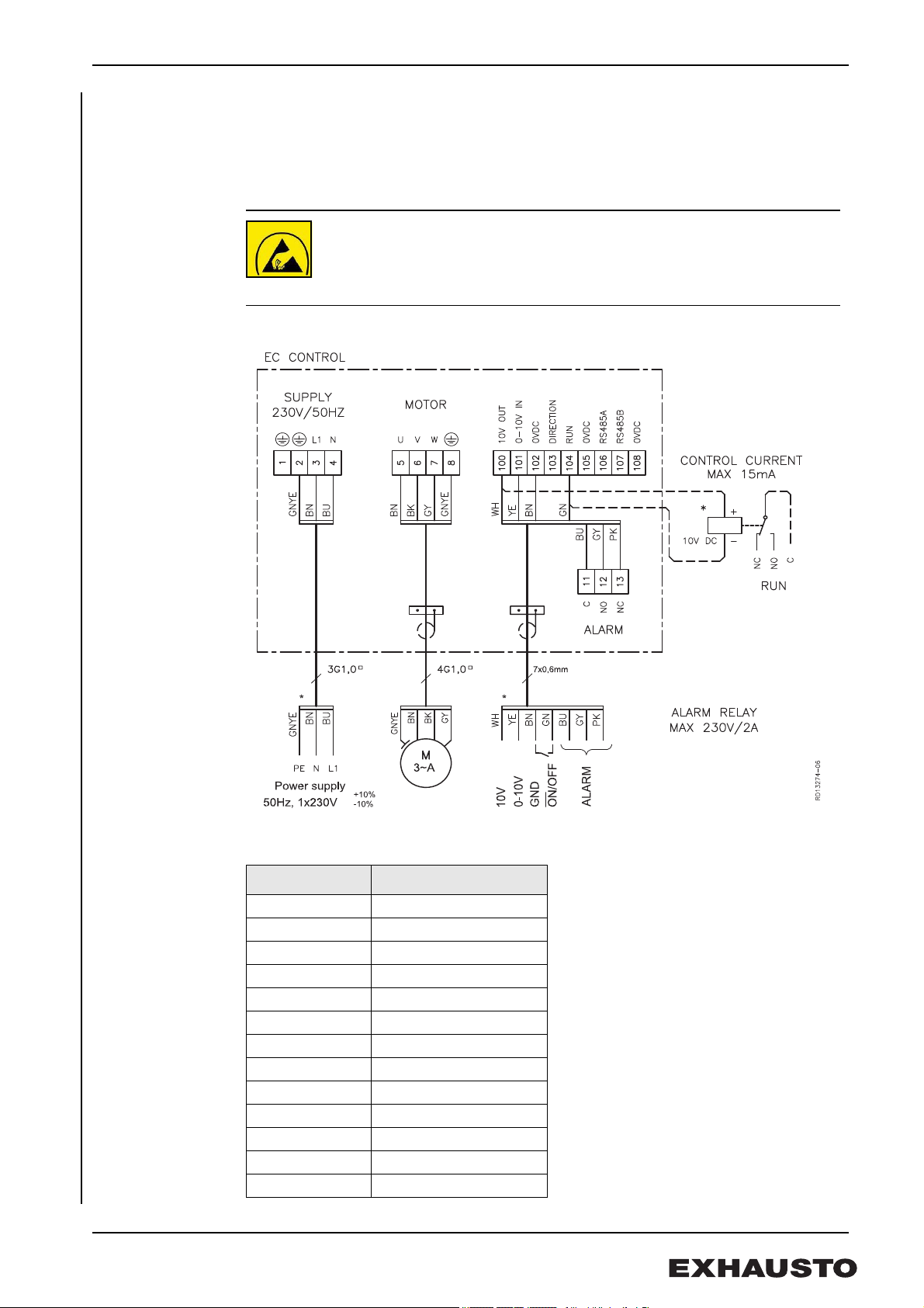
1.3.2 Ventilator with EC control
General Ventilators marked “EC” have built-in EC control system.
Cables Cables for control signals must be screened. The wiring for control signal inputs must
be completely insulated from the supply wirings.
ESD
The electrician must be ESD protected when
• detaching the cover on the EC control
• working with the EC control
BESF160-2-1EC, BESF180-4-1EC, BESF200-4-1EC, BESF225-4-1EC, BESF250-4-1EC
Diagram
Key to diagram
* Not supplied by EXHAUSTO.
Terminal Signal description
100 10 V DC
101 0-10 VDC
102 0 V DC (chassis)
103 Direction of rotation
104 Start/stop
105 0 V DC (chassis)
106 RS485 + (A)
107 RS485 - (B)
108 0 V DC (chassis)
11 Alarm C
12 Alarm NO
13 Alarm NC
9/64
3004349_2017_08_03.fm GB - BESF – Product information
Fig. 10
Leakage current During operation EC control have a leakage current of less than 3.5 mA. The leakage
current must be earthed, as there is a risk of the motor becoming live.
Earth leak circuit
breakers
If current earth leak circuit breakers are fitted in the installation, they must be of
a type that meets the following requirements:
• PFI type A breaker that breaks the circuit when a vagrant current with DC
content (pulsating DC) in accordance with EN 61008.
• The circuit breakers must be marked with the following symbol:
Requirements • Disconnection time of max 0.3 seconds
Dimensioning of
the neutral
conductor
Multiple one-phase BESF with EC installations in a shared network with a common
neutral require special dimensioning of the neutral, as the current is not a pure sine
wave.
Example Three EC motors are installed sharing 3 phases; thus, the neutral current is the sum of
the three motors’ current.
Existing
installations
If you are fitting motors to an existing installation, ensure the neutral conductor can
handle the resultant load.
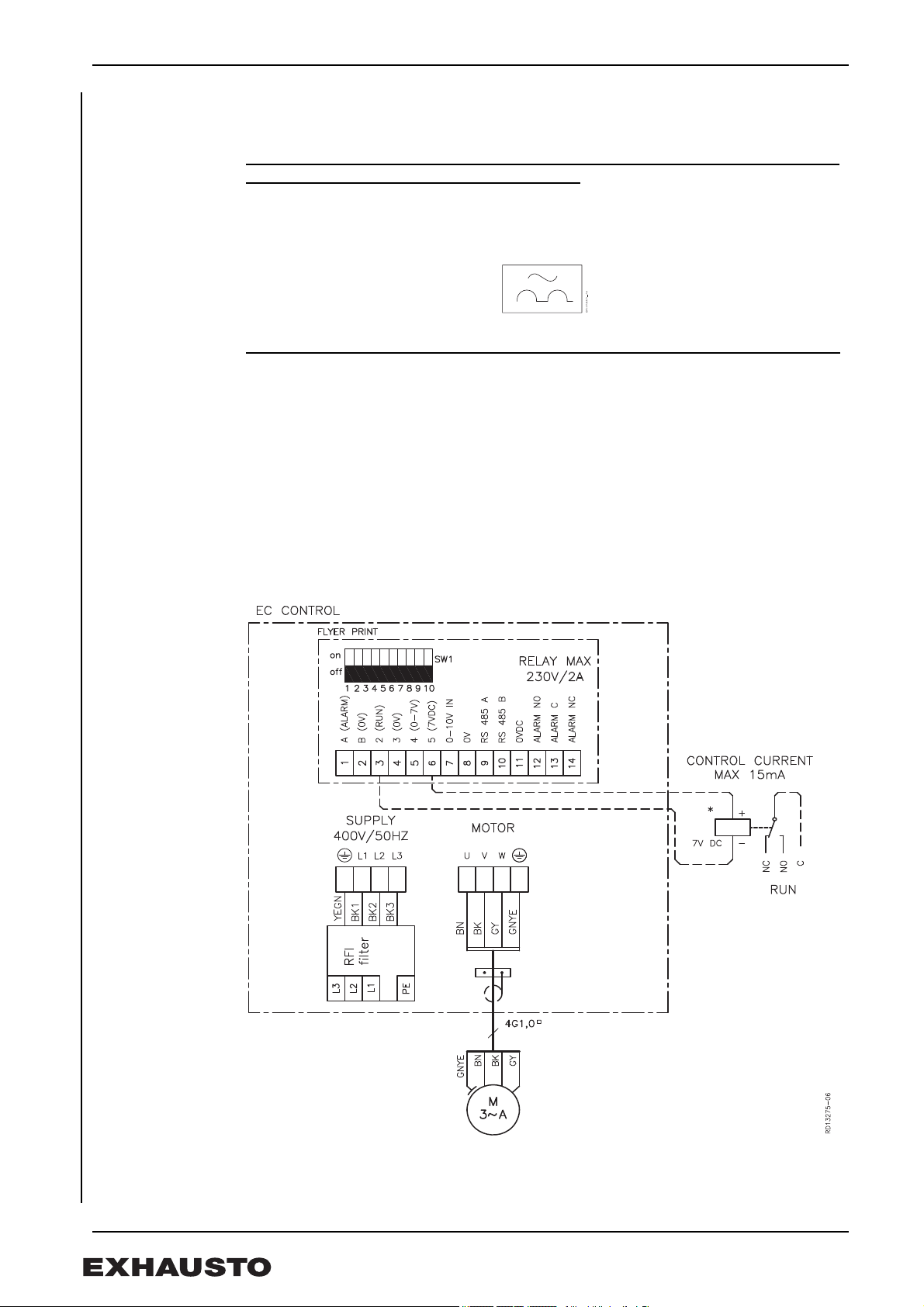
BESF280-4-3EC
Diagram
* Not supplied by EXHAUSTO.
10/64
3004349_2017_08_03.fm GB - BESF – Product information
Key to diagram
Terminal Signal description Comments
1 Alarm in EFC1P panel A
2 0 V DC (chassis) EFC1P panel B
3 Start/stop EFC1P panel 2
4 0 V DC (chassis) EFC1P panel 3
5 0-7 V DC EFC1P panel 4
6 7 V DC EFC1P panel 5
7 0-10 V DC
8 0 V DC (chassis)
9 RS485 + (A)
10 RS485 - (B)
11 0 V DC (chassis)
12 Alarm NO
13 Alarm C
14 Alarm NC
Dipswitch 1 • Dip 1-6: Modbus address
• Dip 7-8 Always OFF
• Dip 9: Analog source(0-10V) or EFC1P
• Dip 10: Always OFF
Dip 9
0-10 Volt OFF
EFC1P panel ON
Leakage current The EC-control system produces a leakage current when running. The leakage current
must be earthed, as there is a risk of the motor becominglive.
A leak current of up to 150 mA can be generated.
The ventilator must be properly earthed to comply with EN50178.
Earth leak circuit
breakers
If current earth leak circuit breakers are fitted in the installation, they must be of
a type that meets the following requirements:
• PFI type B breaker according to EN 61008, that breaks the circuit when a
vagrant current with DC content (pulsating DC) or smooth vagrant current
is registered.
• The circuit breakers must be marked with the following symbols:
11/64

3004349_2017_08_03.fm GB - BESF – Product information
1.3.3 Fault finding: phase-one EC controls
Diodes • Diode 1: Red
• Diode 2: Yellow
• Diode 3: Green
Troubleshooting
chart
Error code Green Red Yellow Error Relay
None + - 1Reserved
2 - + Blinks twice/pauses 4 seconds Below voltage 170 v +
3 - + Blinks three times/pauses 4
4 + - Blinks four times/pauses 4 seconds Overcurrent: Reduced
5Reserved
6 + - Blinks six times/pauses 4 seconds Overheating: Reduced
7 - + Blinks seven times/pauses 4
8 - + Blinks eight times/pauses 4
9 - + Blinks nine times/pauses 4 seconds MCE Fault (IRF Chip
10 - + Blinks 10 times/pauses 4 seconds Motor blocked +
11 - + Blinks 11 times/pauses 4 seconds Motor phase missing +
12 Reserved
13 - + Reserved
14 Reserved
15 Reserved
16 - + Blinks 16 times/pauses 4 seconds Communication error +
• Green diode lights up: no errors
• Red diode lights up: there is an error. Alarm relay has been tripped.
• Yellow diode: blinks for error type
Above voltage 255 v +
seconds
-
rpm
-
rpm
Overheating: Stop +
seconds
Hardware error +
seconds
+
general fault)
NB When the error has been remedied, the LED indicator (LED blink) on the EC control can be reset
by temporarily cutting the power until the LED goes out.
EXHAUSTO provides a two-year manufacturer's warranty on the fan.
12/64

3004349_2017_08_03.fm GB - BESF – Product information
Fig. 11
Fig. 12
Fig. 13
Fig. 14
1.4 Connecting to duct system
Ducts To achieve maximum performance with minimal energy consumption the ventilator
should be connected to the duct system with the specified lengths of duct before and
after the ventilator. The ventilator must always be connected to the duct system using
FLF to avoid any chance of vibrations being transmitted. The spigots on the ventilator
and the OGSR are fitted with rubber seals.
BESF with fitted OGSR BESF without OGSR
Sound The ventilator is fitted with mufflers in accordance with the requirements of the operating
area. The sound pressure for all types of BESF is less than 70 dB (A).
The duct system must be insulated against sound propagation, heat loss and
condensation.
Protective net A protective net (accessory) with a mesh size of 12 mm must be fitted if the ventilator is
not fitted to a duct.
13/64

3004349_2017_08_03.fm GB - BESF – Product information
Fig. 15
1.5 Service and cleaning
Cleaning The ventilator must be cleaned at least twice a year. To clean the ventilator:
Step Action
1 Switch off the power supply to the
unit using the isolation switch
2 Open the service door.
3 Wash the ventilator housing and
the centrifugal impeller thoroughly
with soap and water. The parts
must be dry and the service door
closed before the ventilator is
restarted.
4 The centrifugal impeller can be
removed and cleaned.
Measure the exact position of the
impeller on the axle before
removing it. Make sure that any
weights on the centrifugal impeller
are not removed.
Make sure that cooling air can
move freely through the motor
cover.
Warning! If, once reassembled, the ventilator vibrates violently this might be due to an
imbalance caused by dirt on the centrifugal impeller.
Warranty EXHAUSTO provides a two-year factory warranty on the ventilator, valid from invoice
date.
1.6 Environmental declaration
Product
description
Materials used Cabinet, screw, fan housing and support rails are made of recycleable hot-dip
EXHAUSTO BESF is a an easily serviced radial fan with forward curved blades. The fan
is insulated against fire, noise and heat with 30 mm of mineral wool. The fan impeller is
directly mounted on the motor shaft, thus reducing losses and wear and resulting in
lower repair costs.
Service and cleaning is done by opening the hinged cover. This provides access to all
parts in contact with the air. The motor is mounted outside the airstream.
The fan is supplied with mounting rails with vibration dampers. The fan is CE approved
and EMC tested in accordance with the applicable directives.
galvanised steel sheet. The insulation consists of mineral wool which can be recycled
after dismantling the fan. The gaskets consist of CFC and HCFC free cellular rubber.
The motor consists of aluminium, steel and copper, and in some cases a plastic cooling
jacket. The packaging consists of corrugated cardboard.
14/64

3004349_2017_08_03.fm GB - BESF – Product information
Materials in %
BESF
146
Aluminium 10% 10% 13% 10% 8% 11% 10% 9%
Fe 75% 76% 70% 74% 75% 75% 78% 77%
Copper 4% 4% 2% 2% 2% 3% 4% 4%
Mineral wool 6% 6% 4% 5% 6% 5% 5% 5%
PCB;
electronic
components
Plastic, cellular
rubber
Other 2% 2% 3% 2% 2% 2% 1% 1%
1% 1% 7% 7% 6% 4% 2% 3%
1% 1% 1% < 1% 1% < 1% 1% < 1%
BESF160
Ej EC
BESF
160
BESF
180
BESF
200
BESF
225
BESF
250
BESF
280
15/64
3004349_2017_08_03.fm DK - BESF - Produktvejledning
Fig. 1
1. DK - BESF - Produktvejledning
EXHAUSTO boxventilator BESF anvendes til transport af luft i indblæsnings- og
udsugningsanlæg.
Ventilatoren må ikke anvendes til transport af faste partikler, eller hvor
der er risiko for eksplosive gasarter.
Ventilatoren må ikke startes med åben servicelåge.
1.1 Opbygning
Beskrivelse BESF er en totalisoleret og lydsvag centrifugalventilator med F-hjul:
• BESF146-4-1
• BESF160-4-1
• BESF160-2-1EC
• BESF180-4-1EC
• BESF200-4-1EC
• BESF225-4-1EC
• BESF250-4-1EC
• BESF280-4-3EC
Ventilatoren består indvendigt af et pladeformet ventilatorhus, som er isoleret, og
udvendigt af et kabinet af galvaniseret plade
Temperaturgrænser
Variant
BESF -12ºC 60ºC -30ºC 40ºC
Studsmål Ventilatorens studsmål er i overensstemmelse med Eurovent.
BESF 146 160/180 200/225 250/280
D (mm)
Transport Ventilatoren leveres emballeret og kan
transporteres på sækkevogn. Efter udpakning skal
ventilatoren transporteres og behandles, således at
kabinet og studse ikke deformeres.
Temperatur - medie Temperatur - omivelser, drift
Min. Max. Min. Max.
Ø 160 Ø 200 Ø 250 Ø 315
Størrelse og vægt
BESF 146 160 180 200 225 250 280
Vægt - kg
13 17 22(EC) 23 27 32 41 49
16/64

3004349_2017_08_03.fm DK - BESF - Produktvejledning
RD13285-01
i
b
a
c
d
e
f
g
h
M
a
x
.
6
0
°
C
M
a
x
.
4
0
°
C
j
Fig. 2
Hovedkomponenter
Pos. Part
aKabinet
bServicelåge
c Motor
d Centrifugalhjul
e Ventilatorhus
f Låseskrue (værktøj medleveres)
g Bæreskinner med svingningsdæmpere
h Selvskærende skruer
i Overgangsstykke OSGR (tilbehør). (Ved montage af OGSR skal slidsen altid
være ud for tappen, således at ledepladerne vender korrekt).
j EC-styring/klemkasse
17/64
3004349_2017_08_03.fm DK - BESF - Produktvejledning
Fig. 3
Fig. 3
RD13307-01
D
D
Fig. 4
1.2 Montage
1.2.1 Indendørs placering
Ventilatoren kan indendørs monteres
på forskellige måder (fig. 3).
Ved intermitterende drift, hvor der er
risiko for kondensvand i motoren, må
kun monteringsmetode A og B
benyttes.
Serviceadgang Ved udvælgelse af den nøjagtige
placering skal der være plads til, at
servicelågen kan åbnes 90º.
Advarsel Motoren må aldrig placeres lodret under kabinettet og desuden skal
det sikres, at motor og EC-styring ikke tildækkes, da det vil kunne
forårsage overophedning.
18/64

3004349_2017_08_03.fm DK - BESF - Produktvejledning
Fig. 5
Fig. 6
RD13307-01
D
D
RD13309-01
Fig. 7
1.2.2 Udendørs placering (OD)
Udendørs montering kræver særlig
opmærksomhed, idet det gennem
ekstra fugning og afskærmning
skal sikres, at der ikke trænger
vand ind i konstruktionen.
Motor og eventuel EC-motorstyring er
forberedt for udendørs montering for
pos. A eller B, jf. fig. 5.
Serviceadgang Ved udvælgelse af den nøjagtige
placering skal der være plads til, at
servicelågen kan åbnes ca. 90° og der
skal være adgang til låseskruerne.
1.2.3 Montage af bæreskinner
• Underlaget skal være plant, stabilt og svingningsdødt for at minimere overførslen
af eventuelle svingninger fra ventilatoren. Anvend f.eks. en cementflise oven på
en solid trækonstruktion.
• Monter bæreskinnerne på kabinettet med de medleverede skruer. I
monteringsmetode A er kabinettet forboret.
• Stil ventilatoren løst oven på underlaget. Den skal ikke fastspændes.
19/64

3004349_2017_08_03.fm DK - BESF - Produktvejledning
RD12102-01
Fig. 8
1.3 El-tilslutning
Generelt
El-installationen skal foretages af autoriseret el-installatør.
Ventilator- og motorspecifikationer fremgår af de monterede typeskilte.
Max. forsikring = 13 Amp.
Hvis forsikringen er en ...skal den være med karakteristik
smeltesikring gG eller gM.
automatsikring B ellerC, og opfylde IEC 90947-2.
Max. kortslutningsstrøm er 10 kA
Ved opstart og indregulering af ventilationsanlægget er det vigtigt at kontrollere
motorens omløbsretning, og at strømforbruget ikke overstiger mærkestrømmen på
typeskiltet, da det vil medføre overbelastning af motoren.
Forsyningsadskiller EXHAUSTO A/S gør opmærksom på, at der i henhold til
Maskindirektivet (bilag 1) skal
opsættes en forsyningsadskiller i den
faste installation af ventilatoren.
Forsyningsadskilleren skal...
• være aflåselig, eller placeres synligt i nærheden af ventilatoren.
• kunne afbryde alle poler fra forsyningsspændingen
- kontaktafstand min. 3 mm i hver pol.
• udføres som forsyningsadskiller i hht. IEC 60947-1 eller IEC 60947-3
Forsyningsadskilleren er ikke en del af EXHAUSTO’s leverance.
Lynafledning... ...skal ske i henhold til gældende love og bestemmelser.
1.3.1 Ventilatorer uden EC-styring
El-tilslutning El-tilslutningen foretages iht. el-diagrammet, der findes i låget på motorens klemkasse
(fig. 8).
BESF146-4-1
BESF160-4-1
Alle 1-fasede ventilatorer er spændingsregulerbare.
Motoren er forsynet med termosikring. Termosikringen er fra fabrikken koblet i serie
med motorens strømkreds (eldiagram i klemkassen fig. 1). Hvis der ønskes manuelt
reset ved termisk udfald, anvendes el-diagram fig. 2, hvor termosikringen anvendes i
styrekredsen for en kontaktor.
Motoren er overbelastningsbeskyttet.
20/64
 Loading...