

Exhausto BESB, BESB 500, BESB 250, BESB 315, BESB 400 Series Manual
EXHAUSTO A/S
Odensevej 76
DK-5550 Langeskov
Tel. +45 65 66 12 34
Fax +45 65 66 11 10
exhausto@exhausto.dk
www.exhausto.dk
3004355-2012-07-23.fm
11
BESB

3004355-2012-07-23.fm
GB - BESB – Product information
1.1 Main parts.............................................................................................................4
1.2 Transport ..............................................................................................................5
1.3 Fitting....................................................................................................................5
1.3.1 Fitting indoors ...............................................................................................5
1.3.2 Fitting outdoors (OD)..................................................................................... 6
1.3.3 Fitting the mounting bars............................................................................... 6
1.4 Wiring....................................................................................................................7
1.4.1 Ventilator without frequency converter..........................................................7
1.4.2 Ventilator with frequency converter FC .........................................................8
1.4.3 Fault finding one-phase FC motors...............................................................9
1.5 Connecting to duct system:..............................................................................11
1.6 Airflow measurement ........................................................................................12
1.7 Service and cleaning ......................................................................................... 13
DK - BESB - Produktvejledning
1.1 Opbygning..........................................................................................................14
1.2 Transport ............................................................................................................15
1.3 Montage ..............................................................................................................15
1.3.1 Indendørs placering ....................................................................................15
1.3.2 Udendørs placering (OD) ............................................................................16
1.3.3 Montage af bæreskinner .............................................................................16
1.4 El-tilslutning .......................................................................................................17
1.4.1 Ventilatorer uden frekvensomfomer ............................................................17
1.4.2 Ventilatorer med frekvensomformer FC ......................................................18
1.4.3 Fejlfinding for 1-fasede FC-motorer ............................................................ 19
1.5 Kanaltilslutning..................................................................................................21
1.6 Luftmængdemåling............................................................................................ 22
1.7 Service og rengøring.........................................................................................23
D - BESB - Betriebsanleitung
1.1 Aufbau.................................................................................................................24
1.2 Transport ............................................................................................................25
1.3 Montage ..............................................................................................................25
1.3.1 Aufstellung in Innenräumen ........................................................................25
1.3.2 Aufstellung im Freien (OD).......................................................................... 26
1.3.3 Montage von Tragschienen.........................................................................26
1.4 Elektrischer Anschluss ..................................................................................... 27
1.4.1 Ventilatoren ohne Frequenzwandler ........................................................... 27
1.4.2 Ventilatoren mit Frequenzwandler FC......................................................... 28
1.4.3 Fehlersuche bei einphasigen FC-Motoren ..................................................29
1.5 Kanalanschluss..................................................................................................31
1.6 Luftmengenmessung.........................................................................................32
1.7 Wartung und Reinigung ....................................................................................33
N - BESB - Produktveiledning
1.1 Oppbygning........................................................................................................34
1.2 Transport ............................................................................................................35
1.3 Montering............................................................................................................35
1.3.1 Innendørs plassering ..................................................................................35
1.3.2 Utendørs plassering (OD) ........................................................................... 36
1.3.3 Montering av bæreskinner...........................................................................36
1.4 Elektrisk tilkobling.............................................................................................37
1.4.1 Vifter uten frekvensomfomer .......................................................................37
1.4.2 Vifter med frekvensomformer FC ................................................................38
1.4.3 Feilsøking for enfasede FC-motorer............................................................39
1.5 Kanaltilkobling ...................................................................................................41
1.6 Luftmengdemåling.............................................................................................42
1.7 Service og rengjøring........................................................................................43
2/56

3004355-2012-07-23.fm
S – BESB – Produkthandbok
1.1 Konstruktion.......................................................................................................44
1.2 Transport ............................................................................................................45
1.3 Montering............................................................................................................45
1.3.1 Inomhusmontering ......................................................................................45
1.3.2 Placering utomhus (OD)..............................................................................46
1.3.3 Montering av bärskenor...............................................................................46
1.4 Elanslutning ....................................................................................................... 47
1.4.1 Fläktar utan frekvensomvandlare................................................................47
1.4.2 Fläktar med frekvensomvandlare FC ..........................................................48
1.4.3 Felsökning för 1-fas FC-motorer .................................................................49
1.5 Kanalanslutning.................................................................................................51
1.6 Mätning av luftmängd........................................................................................52
1.7 Service och rengöring.......................................................................................53
3/56

3004355-2012-07-23.fm GB - BESB – Product information
- +
m
RD11279-01
Fig. 1
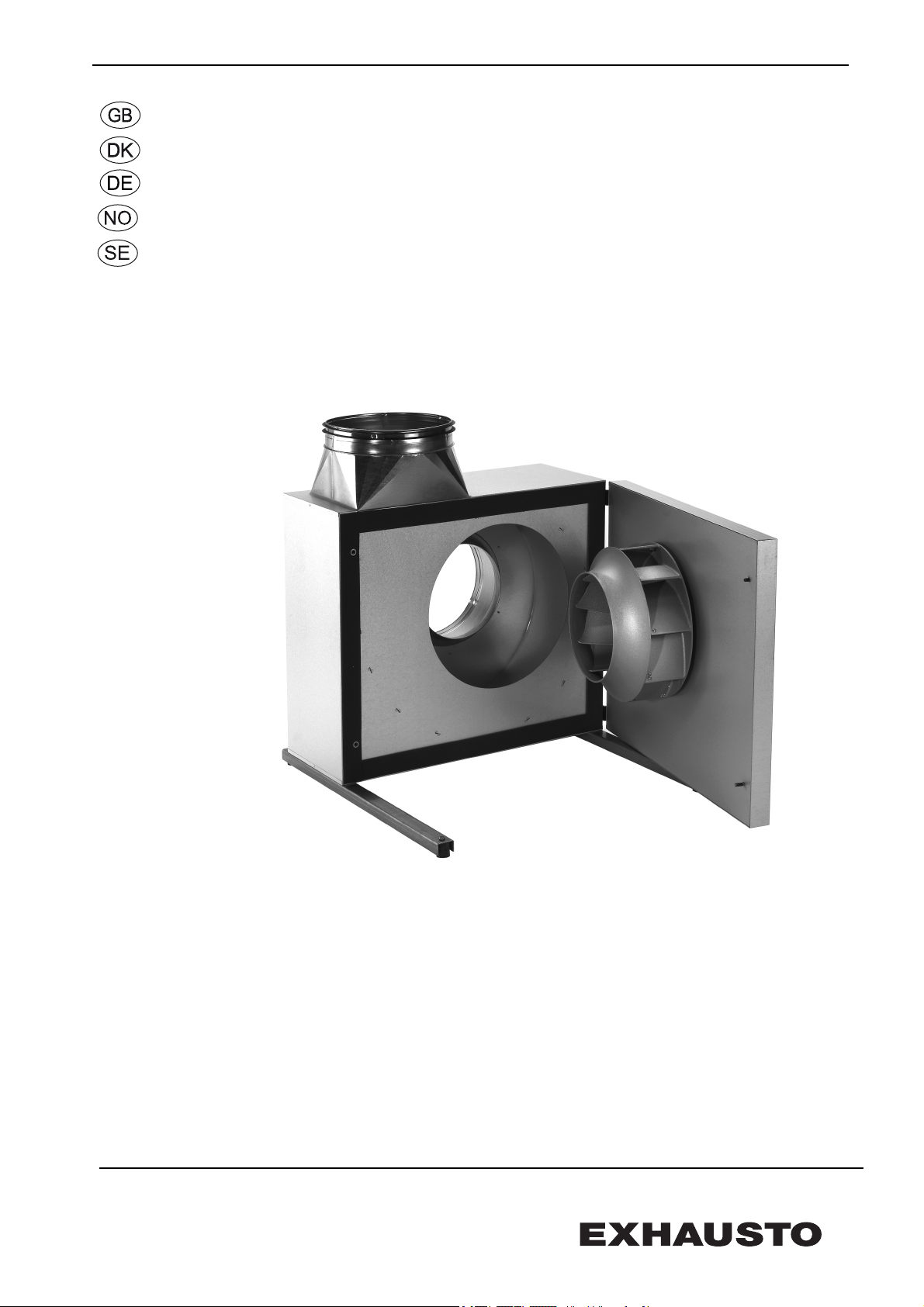
1. GB - BESB – Product information
EXHAUSTO BESB box ventilators are used in air supply and extraction systems.
The ventilator is not to be used to transport solid particles, nor in areas
where there is a risk of explosive gases.
The ventilator must not be started with the service door open.
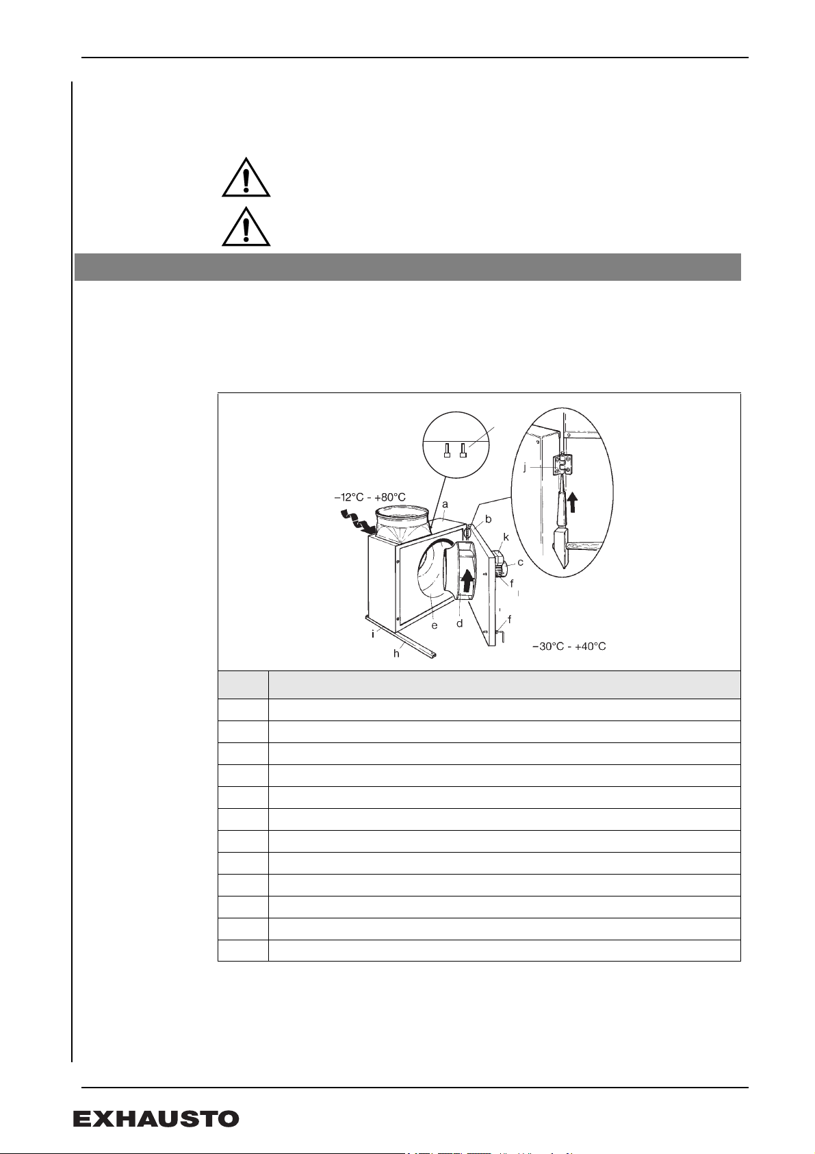
1.1 Main parts
BESB is available in four different sizes, is completely insulated, and has a low-noise
centrifugal fan with cast aluminium backward-bent blades (B-impeller). The ventilator
has an internal insulated housing and an external cabinet, both made of sheet
aluminium.
Main components
Pos. Part
a Cabinet
b Service door
c Motor
d B-impeller
e Fan housing
f Locking screws (supplied with screwdriver)
g Handle
h Mounting bars with vibration damper
i Self-tapping screws
j Hinges
k Frequency converter / terminal box
m Air flow measuring probes (not included with BESB250)
Min. operating temperature: -12°C max. operating temperature +80°C
Ambient temperature when running: min. -30°C max. +40°C
4/56
3004355-2012-07-23.fm GB - BESB – Product information
Fig. 2
RD11358-01
Fig. 3
1.2 Transport
The ventilator is delivered packaged and can be transported on a pallet. Once unpacked
the ventilator should be handled carefully, especially the spigots etc. Deformation could
result in internal damage to the moving parts.
If there is not a lot of space to move the ventilator, the service door can be dismounted
as shown in section 1.1.
NB The ventilator must not be lifted using the service door handle.
Weight
BESB 250 315 400 500
kg 50 54 (FC) 59 61 (FC) 92 105 97 (-3FC)
1.3 Fitting
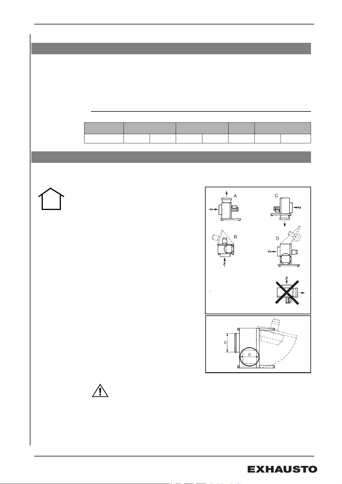
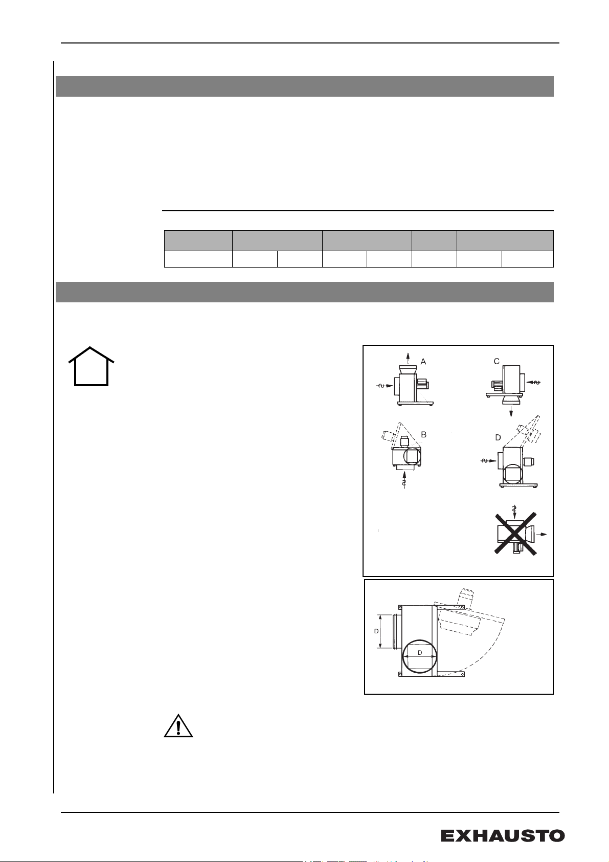
1.3.1 Fitting indoors
There are various ways of fitting the
ventilator indoors (Fig. 2).
With methods B and D the service door
must be kept in the open position during
service. A safety fitting for this purpose can
be supplied (including an assembly kit).
If the ventilator is to run intermittently, there
is a risk of condensation in the motor.
Therefore, use mounting method A or B
only.
Service access Wherever the ventilator is fitted, there
should be space enough to be able to open
the service door to an angle of approx. 80°
and to access the locking screws.
Warning The motor must never be placed vertically under the cabinet and the
motor and frequency converter must never be covered or they will
overheat.
5/56
3004355-2012-07-23.fm GB - BESB – Product information
A
B
C
D
Fig. 4
Fig. 5
RD11358-01
RD12105-01
Fig. 6
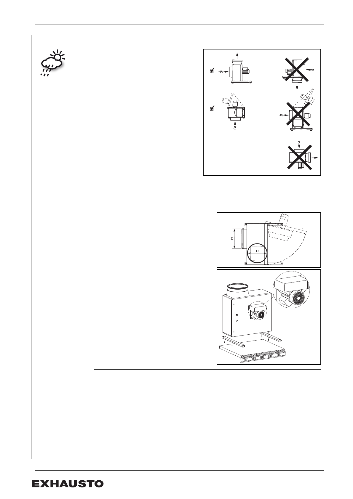
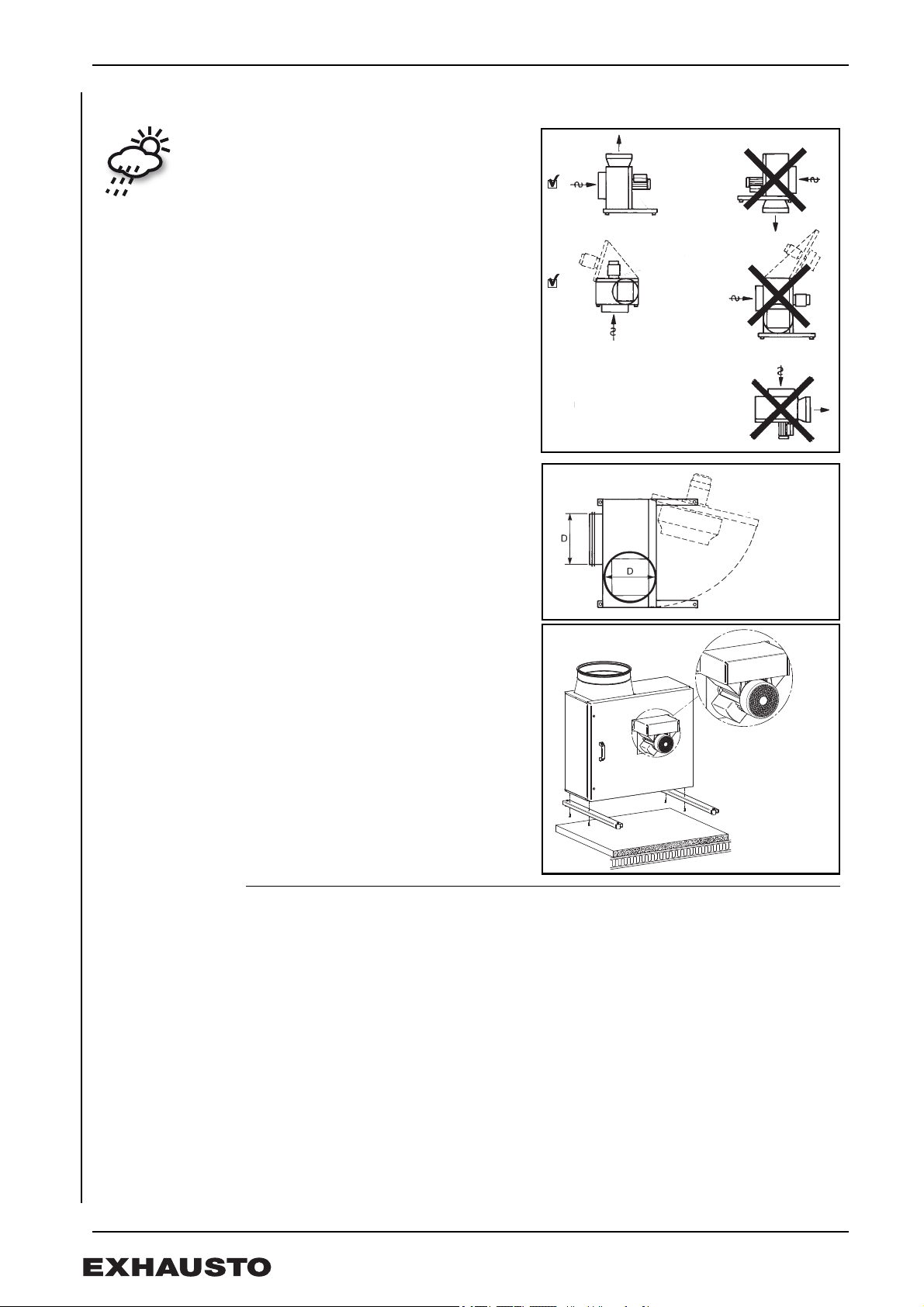
1.3.2 Fitting outdoors (OD)
OD type ventilators are designed for
outdoor use.
A and B fitting methods should be
used for outdoor fitting. Fitting
methods C and D require a specially
designed ventilator (Fig. 4) — contact
EXHAUSTO.
All exterior seams, including spigots
have been jointed to prevent water from
getting inside.
The cabinet is class C4 DS/EN ISO12
944.2 certified and designed for
outdoors.
Service access Wherever the ventilator is fitted, there should
be space enough to be able to open the
service door to an angle of approx. 80° and to
access the locking screws.
Ventilator and
frequency
converter
1.3.3 Fitting the mounting bars
The motor of the FCOD-type BESB ventilator
is covered to prevent outdoor condensation
damaging the electronics (Fig. 6).
• Mounting should be done on a stable vibration-resistant base, to minimise any
vibration that might be caused by the ventilator. A cement slab placed on a
wooden base construction is recommended.
• Fit the mounting bars on the cabinet with the supplied fitting screws. The cabinet
has holes already bored for fitting method A.
• BESB 400 and 500: When using fitting method B (Fig. 2/4) for BESB 400 and
500, holes (Ø16 - Ø20) are bored in the cabinet for the fitting of the mounting
bars.
• Fit the mounting bars while the ventilator is on the pallet.
• Sit the ventilator on the supporting base. Do not fasten the ventilator to the base.
6/56
3004355-2012-07-23.fm GB - BESB – Product information
Fig. 7
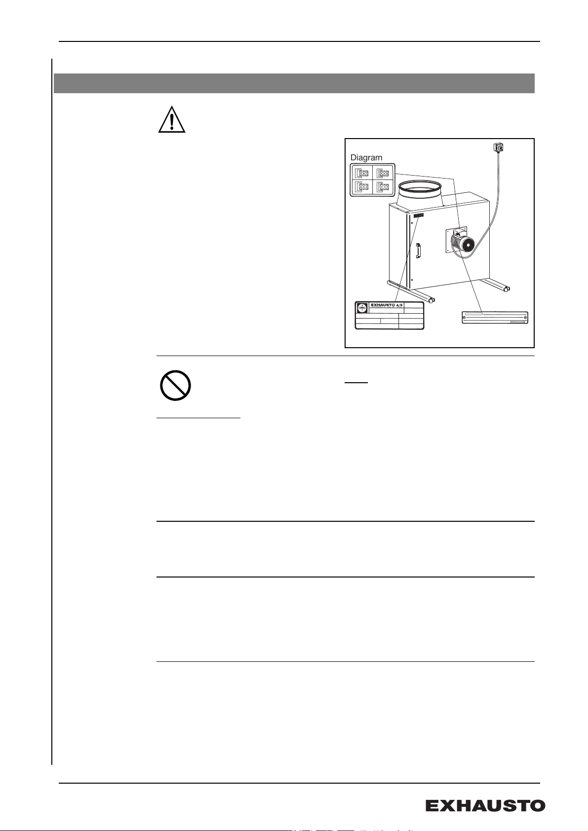
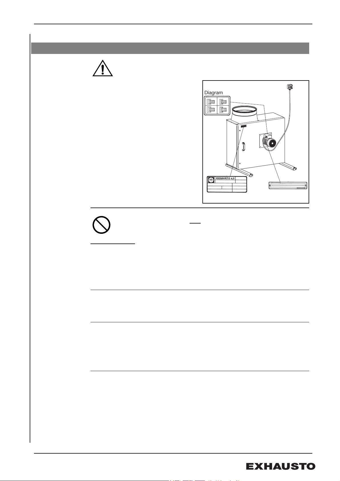
1.4 Wiring
General
Wiring of the ventilator should only be performed by a qualified electrician.
The ventilator and motor specifications
are listed on the ventilator’s type plate.
Max. fuse rating = 13 Amp.
At start-up and during the initial
adjustment of the ventilator, it is important
to control the direction of rotation of the
motor and to check the motor current does
not exceed the manufacturer’s
recommended rated current for the motor
(to avoid damaging the motor).
Repair
switch
The switch must …
EXHAUSTO A/S stresses that according to the Machine Directive
(Appendix 1), a repair switch must
the ventilator.
• be lockable or positioned in plain sight in the immediate vicinity of the
ventilator.
• be able to disconnect all poles from the electrical supply.
– contact distance of at least 3 mm in each pole.
• set up as a power supply isolator in accordance with standard EN 60
204-1.
The repair switch is not supplied by EXHAUSTO.
be fitted in the fixed installation of
1.4.1 Ventilator without frequency converter
Wiring Wiring should be done as stipulated in the electrical drawing in the door of the motor's
terminal box (Fig. 7).
BESB250-4-1,
BESB315-4-1
All one-phase ventilators are voltage regulated.
The motor is fitted with a thermal cut-out. The thermal-cut out is factory installed and
wired in series to the motor's power circuit (electrical diagram in the terminal box fig. 1).
Use the circuit diagram (Fig. 2) if a manual reset is required after a thermal cut-out,
where the thermal cut-out is used as a contact in the control circuit.
The motor has overload protection.
BESB500-4-3 The ventilator has a three-phase motor, which cannot be voltage regulated.
NB The motor does not have a thermal cut-out and should have a correctly rated
circuit breaker installed.
The motor can be regulated using an installed external frequency converter max. 50 Hz.
7/56
3004355-2012-07-23.fm GB - BESB – Product information
Fig. 8
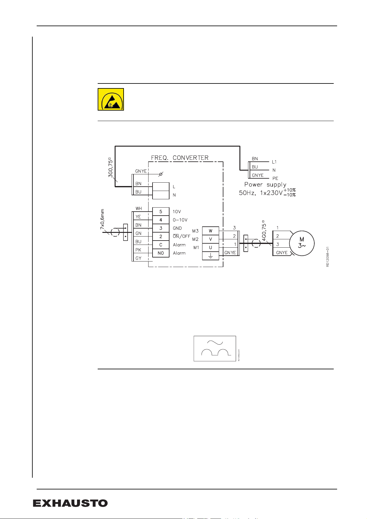
1.4.2 Ventilator with frequency converter FC
General Ventilators marked FC have a built-in frequency converter.
Cables Cables for control signals must be screened. The wiring for control signal inputs must
be completely insulated from the supply wirings.
ESD
The electrician must be ESD protected when
• detaching the cover on the frequency converter
• working with the frequency converter
BESB250-4-1FC, BESB315-4-1FC, BESB400-4-1FC, BESB500-4-1FC
Diagram
Leakage current When operating the FC-motor frequency converters have a leakage current of less than
3.5 mA. The leakage current must be earthed, as there is a risk of the motor becoming
live.
Earth leak circuit
breakers
Dimensioning of
the neutral
conductor.
Example For example if three FC motors are installed, sharing 3-phases, the neutral current is the
Existing
installations
Only Type-A earth leak circuit breakers can be used with one-phase FC motors, as
required by IEC755 (Amendment 2). The circuit breaker activates when faulty current is
registered with DC component. These circuit breakers are marked with:
Multiple one-phase BESB with FC installations in a shared network with a common
neutral, require special dimensioning of the neutral, as the current is not a pure sine
wave.
sum of the three motors’ current.
If you are fitting motors to an existing installation, check that the neutral conductor can
cope with the resultant load.
8/56
3004355-2012-07-23.fm GB - BESB – Product information
RD12119-01
Fig. 9
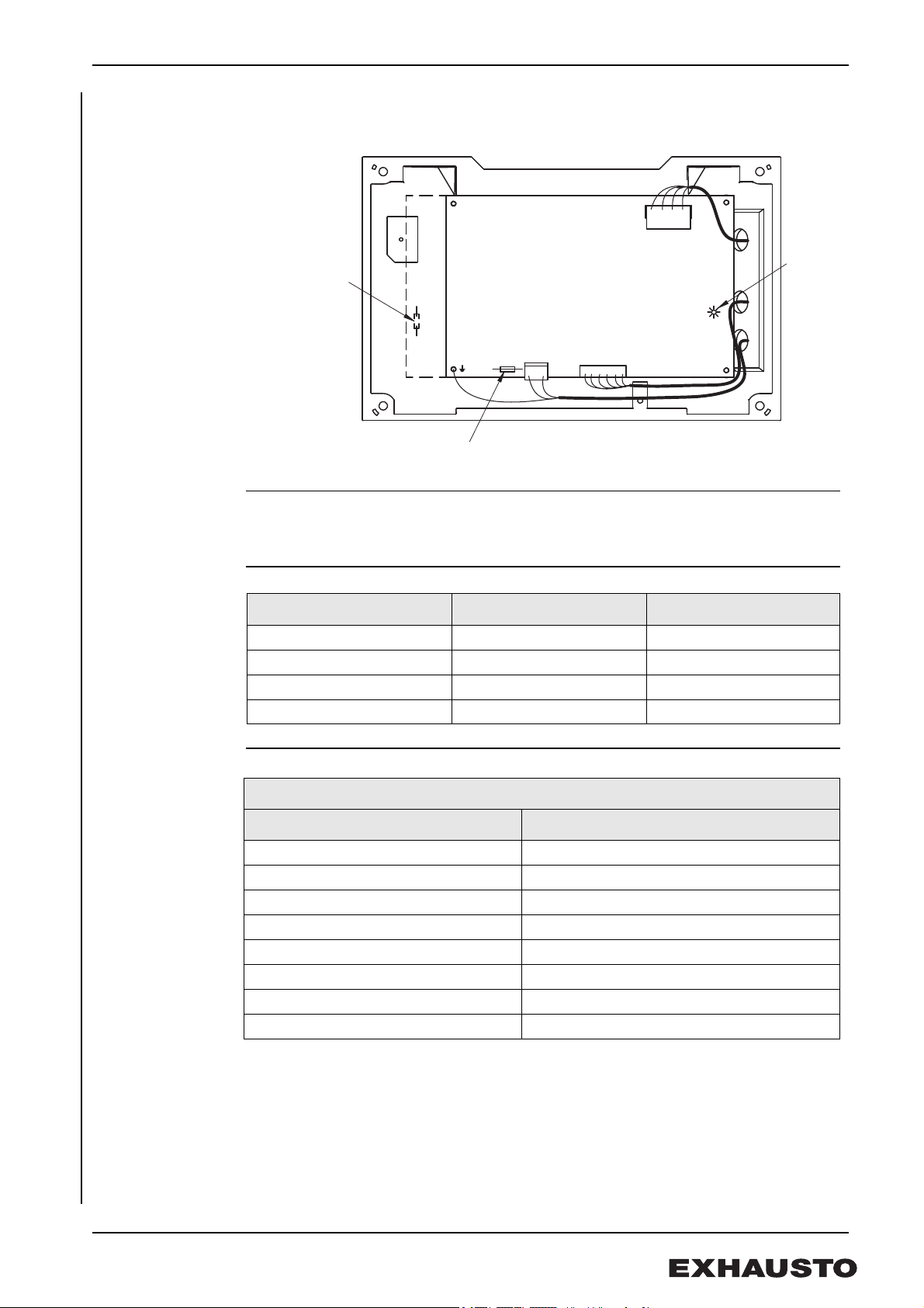
LED
Fitting fuses for the
BESB250 and BESB315
Fitting fuses
for the
BESB400 and
BESB500
1.4.3 Fault finding one-phase FC motors.
Frequency
converter fuses
LED does not light Check:
• The mains is 1 X 230 V
• fuses
Fuse table
BESB400-4-1FC 2 10A T10AH
BESB500-4-1FC 2 10A T10AH
Fault finding chart
Once every second Normal operation.
Once every four seconds Fault: High temperature
Blinks twice every four seconds Fault: Low voltage
Blinks three times every four seconds Fault: Overvoltage (generator)
Blinks four times every four seconds Fault: Overload (motor current )
Blinks five times every four seconds Fault: Output module fault
Blinks six times every four seconds Fault: Communication time-out
Blinks seven times every four seconds Fault: Phase error
Ventilator type Fuse rating Typ e
BESB250-4-1FC 4A T4AH
BESB315-4-1FC 4A T4AH
The green LED indicates:
LED blinking: Description
When the error has been remedied, the LED indicator of the frequency converter can be
reset by temporarily cutting the power until the LED goes out.
9/56
3004355-2012-07-23.fm GB - BESB – Product information
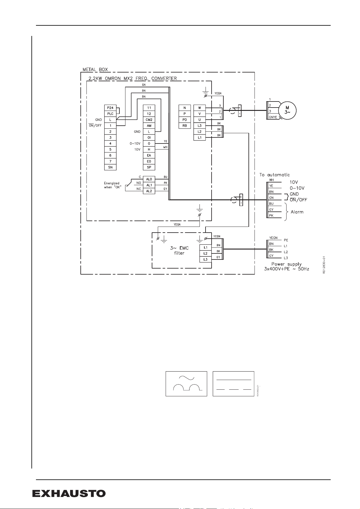
Fig. 10
BESB500-4-3FC
Diagram
Leakage current The FC- motor’s frequency converter produces a leakage current when running. The
leakage current must be earthed, as there is a risk of the motor becoming live.
A leakage current of up to 150 mA can be generated.
To comply with EN50178 the unit must be suitably earthed.
Earth leak circuit
breakers
Only type-B circuit breakers must be used with model BESB500-4-3FC in compliance
with IEC755 Amend. 2, for faulty current with DC component (pulsating DC) and for
smooth vagrant current.
These circuit breakers are marked with:
Fault finding See the instruction manual for the frequency converter (in the electronic housing).
When the error has been remedied, the LED indicator of the frequency converter can be
reset by temporarily cutting the power until the LED goes out.
10/56

3004355-2012-07-23.fm GB - BESB – Product information
RD11360-01
Fig. 11
RD11361-01
Fig. 12
Fig. 13
1.5 Connecting to duct system:
Flexible
connections
Sound pressure
level
The ventilator must always be connected to the duct system with FLF, to avoid any
chance of vibrations being transmitted. The spigots on the ventilator are standard-sized
and fitted with rubber seals.
To achieve maximum performance with minimal energy consumption the ventilator
should be connected to the duct system with the specified lengths of duct before and
after the ventilator. The FLF connections must always be fitted as shown.
The ventilator is fitted with sound dampers suited to the requirements of the operating
area. The sound pressure for all types of BESB is less than 70 dB (A). The duct system
is insulated against sound propagation, heat loss, fire and condensation.
No Duct A protective net (accessory) with mesh size of 12 mm must be fitted if the ventilator is
not fitted to a duct. It should be noted that:
• such fittings result in a pressure drop in the system
• Air volume measurements cannot be measured correctly when there is no duct
fitted on the suction side
11/56
3004355-2012-07-23.fm GB - BESB – Product information
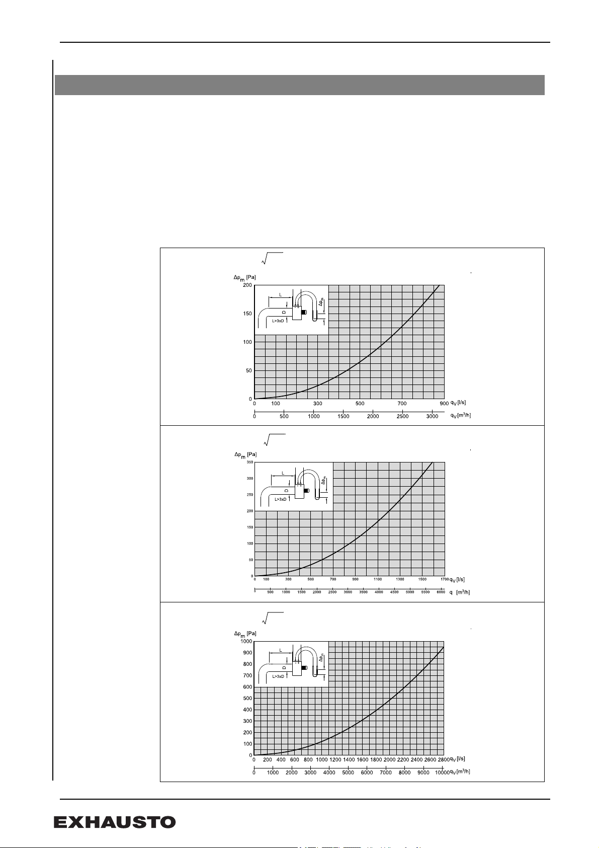
qv62 Δp
m
× ls⁄[]=
qv85 Δp
m
× ls⁄[]=
qv91 Δp
m
× ls⁄[]=
1.6 Airflow measurement
The box ventilators, apart from model BESB250, have measuring points for determining
air flow. A manometer is connected to the test points and the air flow (qv) can be
calculated by using the formula and diagrams.
Margin of error < ± 8% of actual air flow with the duct system on the suction side is as
shown on the diagrams.
Calculations are based on the following conditions:
Temperature: 20°C
Density: 1.2 kg/m3
Pressure measurement, Δpm [Pa], at 20°C
1 m3/s = 1000 l/s = 3600 m3/h
BESB315:
BESB400:
BESB500:
12/56

3004355-2012-07-23.fm GB - BESB – Product information
Fig. 14
02
01
03
13
04
07
06
11
12
08
09
10
05
RD12107-01
Fig. 15
1.7 Service and cleaning
EXHAUSTO provides a two-year factory warranty on the box ventilator, valid from
invoice date. The motor in an EXHAUSTO box ventilator is fitted with special ball
bearings that are lubricated and sealed, and maintenance-free. Any replacement of
these bearings should be carried out by technicians from EXHAUSTO SERVICE or
similarly qualified professionals.
The ventilator must be cleaned at least once a year. To clean the ventilator:
• Switch off the power supply to the
ventilator using the repair circuit
breaker. Open the service door when
the fan has stopped running.
• Wash the ventilator housing and the
centrifugal impeller thoroughly with
soap and water. The parts must be
dry and the service door closed
before the ventilator is restarted.
• The centrifugal impeller can be
dismounted and cleaned. Measure
the exact position of the impeller on
the axle before removing it. The
factory position of the impeller is
shown on the cabinet behind the
service door. If there are weights on
the centrifugal impeller do not remove
them.
• Check that cooling air can move
freely through the motor cover.
Spare parts Ventilator components that can be ordered as spare parts are marked with position
numbers. When ordering spare parts supply the ventilator type and the production order
number (PO); both can be read on the information plate.
Spare parts
1. B-impeller
2. Motor plate
3. Axle extender
4. Frequency converters
(for BESB250-4-1FC, BESB315-4-1FC, BESB400-4-1FC,
BESB500-4-1FC, BESB500-4-3FC)
5. Covering
6. Condensator (for BESB250-4-1, BESB315-4-1)
7. Motor
8. Ball bearings N-side
9. Ball bearings D-side
10. Service door
11. Handle
12. Locking screws
13. 2 x Mounting rail with vibration damper
EXHAUSTO reserves the right to introduce changes to these guidelines without prior
notice.
13/56
3004355-2012-07-23.fm DK - BESB - Produktvejledning
Fig. 1
- +
m
RD11279-01
1. DK - BESB - Produktvejledning
EXHAUSTO boxventilator BESB anvendes til transport af luft i indblæsnings- og
udsugningsanlæg.
Ventilatoren må ikke anvendes til transport af faste partikler, eller hvor
der er risiko for eksplosive gasarter.
Ventilatoren må ikke startes med åben servicelåge.
1.1 Opbygning
BESB findes i 4 størrelser og er en totalisoleret og lyd-svag centrifugalventilator med
bagudbøjede skovle (B-hjul) i støbt aluminium. Ventilatoren består indvendigt af et
ventilatorhus, som er isoleret, og udvendigt af et kabinet, begge dele af aluzink.
Hovedkomponenter
Pos. Part
a Kabinet
b Servicelåge
c Motor
d Centrifugalhjul (B-hjul)
e Ventilatorhus
f Låseskrue (værktøj medleveres)
gHåndtag
h Bæreskinne med svingningsdæmpere
i Selvskærende skrue
j Hængsel
k Frekvensomformer/klemkasse
m Målestudse til luftmængde måling (ikke BESB250)
Temperatur medie min.: -12°C max.: +80°C
Temperatur omgivelser, drift min.: -30°C max.: +40°C
14/56
3004355-2012-07-23.fm DK - BESB - Produktvejledning
Fig. 2
RD11358-01
Fig. 3
1.2 Transport
Ventilatoren leveres emballeret og kan transporteres på træpalle. Efter udpakning skal
ventilatoren transporteres og behandles således, at kabinet og studse m.v. ikke
deformeres, da dette kan forårsage berøring imellem roterende dele og heraf følgende
behov for efterjustering/reparation.
Ved transport gennem trange passager ind til opstillingsstedet, er der mulighed for
demontering af servicelågen som vist i afsnit 2.1” Opbygning”.
Bemærk Ventilatoren må ikke løftes i håndtaget på servicelågen.
Vægt
BESB 250 315 400 500
(kg) 50 54(FC) 59 61(FC) 92 105 97(-3FC)
1.3 Montage
1.3.1 Indendørs placering
Ventilatoren kan indendørs monteres på
forskellige måder (fig. 2).
Ved monteringsmetode B og D skal
servicelågen kunne fastholdes i åben
position ved servicering. Til dette formål
kan leveres et sikkerhedsbeslag incl.
monteringssæt som tilbehør.
Ved intermitterende drift, hvor der er risiko
for kondensvand i motoren, må kun
monteringsmetode A eller B benyttes.
Serviceadgang Ved udvælgelse af den nøjagtige placering
skal der være plads til, at servicelågen kan
åbnes ca. 80° og der skal være adgang til
låseskruerne.
Advarsel Motoren må aldrig placeres lodret under kabinettet og desuden skal det
sikres, at motor og eventuelt frekvensomformer ikke tildækkes, d a det vil
kunne forårsage overophedning.
15/56
3004355-2012-07-23.fm DK - BESB - Produktvejledning
A
B
C
D
Fig. 4
RD11358-01
Fig. 5
RD12105-01
Fig. 6
1.3.2 Udendørs placering (OD)
Hvis ventilatoren har typebetegnelsen OD
er det en udendørs variant.
Ved udendørs montage skal
monteringsmetode A eller B benyttes.
Monteringsmetode C og D kræver en
specialbygget ventilator - kontakt
EXHAUSTO (fig. 4).
Alle udvendige samlinger samt studse er
fuget for at forhindre vandindtrængning.
Kabinettets materialer opfylder kravene til
klasse C4 iht. DS/EN ISO12 944.2 og er
egnet til udendørs placering.
Serviceadgang Ved udvælgelse af den nøjagtige
placering skal der være plads til, at
servicelågen kan åbnes ca. 80° og der
skal være adgang til låseskruerne.
Ventilatorer med
frekvensomformer
Ved udendørsopstilling af BESB med
typebetegnelsen FCOD er motoren
overdækket for at undgå
kondensdannelse i elektronikdelen (fig.
6).
1.3.3 Montage af bæreskinner
• Underlaget være plant, stabilt og svingningsdødt for at minimere overførslen af
eventuelle svingninger fra ventilatoren. Anvend f.eks. en cementflise oven på en
solid trækonstruktion.
• Monter bæreskinnerne på kabinettet med de medleverede skruer. I
monteringsmetode A er kabinettet forboret.
• BESB 400 og 500: Når monteringsmetode B (fig. 2/4) vælges til BESB 400 og
500, bores frihuller (Ø16 - Ø20) i kabinettet for møtrikkerne på bæreskinnerne.
• Monter bæreskinnerne mens ventilatoren ligger på træpallen af hensyn til
transporten.
• Stil ventilatoren løst oven på underlaget. Den skal ikke fastspændes.
16/56
3004355-2012-07-23.fm DK - BESB - Produktvejledning
Fig. 7
1.4 El-tilslutning
Generelt
El-installationen skal foretages af autoriseret el-installatør.
Ventilator- og motorspecifikationer fremgår
af de monterede typeskilte.
Max. forsikring = 13 Amp.
Ved opstart og indregulering af
ventilationsanlægget er det vigtigt at
kontrollere motorens omløbsretning, og at
strømforbruget ikke overstiger
mærkestrømmen på typeskiltet, da det vil
medføre overbelastning af motoren.
Reparationsafbryder
Afbryderen skal...
EXHAUSTO A/S gør opmærksom på, at der i henhold til
Maskindirektivet (bilag 1) skal
faste installation af ventilatoren.
• være aflåselig, eller placeres synligt i nærheden af ventilatoren.
• kunne afbryde alle poler fra forsyningsspændingen
- kontaktafstand min. 3 mm i hver pol.
• udføres som forsyningsadskiller i hht. EN 60 204-1
Reparationsafbryderen er ikke en del af EXHAUSTO’s leverance.
opsættes en reparationsafbryder i den
1.4.1 Ventilatorer uden frekvensomfomer
El-tilslutning El-tilslutningen foretages iht. el-diagrammet, der findes i låget på motorens klemkasse
(fig. 7).
BESB250-4-1,
BESB315-4-1
Alle 1-fasede ventilatorer er spændingsregulerbare.
Motoren er forsynet med termosikring. Termosikringen er fra fabrikken koblet i serie
med motorens strømkreds (eldiagram i klemkassen fig. 1). Hvis der ønskes manuelt
reset ved termisk udfald, anvendes el-diagram fig. 2, hvor termosikringen anvendes i
styrekredsen for en kontaktor.
Motoren er overbelastningsbeskyttet.
BESB500-4-3 Ventilatoren er forsynet med en 3-faset normmotor, som ikke kan spændingsreguleres.
Bemærk Motoren indeholder ikke termosikring og skal overbelastningsbeskyttes ved
hjælp af et motorværn som indstilles på motorens mærkestrøm.
Motoren kan frekvensreguleres fra en ekstern frekvensomformer indstillet på
max. 50 Hz.
17/56
 Loading...