

Page 1
AXS-200/635i
Copper, VDSL2, ADSL2+ and IP
Triple-Play Test Set
User Guide
Page 2

Copyright © 2010–2011 EXFO Inc. All rights reserved. No part of this
publication may be reproduced, stored in a retrieval system or transmitted
in any form, be it electronically, mechanically, or by any other means such
as photocopying, recording or otherwise, without the prior written
permission of EXFO Inc. (EXFO).
Information provided by EXFO is believed to be accurate and reliable.
However, no responsibility is assumed by EXFO for its use nor for any
infringements of patents or other rights of third parties that may result from
its use. No license is granted by implication or otherwise under any patent
rights of EXFO.
EXFO’s Commerce And Government Entities (CAGE) code under the North
Atlantic Treaty Organization (NATO) is 0L8C3.
The information contained in this publication is subject to change without
notice.
Trademarks
EXFO’s trademarks have been identified as such. However, the presence
or absence of such identification does not affect the legal status of any
trademark.
Units of Measurement
Units of measurement in this publication conform to SI standards and
practices.
Version number: 3.0.0
ii AXS-200/635i
Page 3

Contents
Contents
Certification Information ....................................................................................................... vi
1 Introducing the Copper, VDSL2, ADSL2+ and IP Triple-Play Test Set ........ 1
Main Features .........................................................................................................................1
Cable Connections ..................................................................................................................4
LED Indicators .........................................................................................................................5
Electrical Safety Information ...................................................................................................5
ADSL2+ Basic Principles .........................................................................................................6
VDSL2 .....................................................................................................................................6
Navigating through the AXS-200/635i ....................................................................................7
Conventions ............................................................................................................................8
2 Getting Started with Fault Isolation Tools ................................................. 9
Dialer Function .....................................................................................................................10
Regional Settings ..................................................................................................................15
Saving Results .......................................................................................................................20
Reading Saved Results ..........................................................................................................23
3 Auto Tests ................................................................................................... 25
Configuring CQ Auto Tests ....................................................................................................25
Running CQ Auto Tests and Viewing Results .........................................................................37
Inactive Pair Test ...................................................................................................................45
Configuring Inactive Pair Test ................................................................................................45
Running Inactive Pair Test and Viewing Results .....................................................................49
Final/Active Pair Test ..............................................................................................................54
Configuring Final/Active Pair Test ..........................................................................................54
Running Final/Active Pair Test and Viewing Results ...............................................................59
Video-DSL Rate Prediction ....................................................................................................62
Configuring Video-DSL Rate Prediction .................................................................................62
Running Video-DSL Rate Prediction Tests and Viewing Results .............................................68
4 POTS Auto Test ............................................................................................ 79
5 Multi-meter Tests ....................................................................................... 81
Multi-meter ..........................................................................................................................81
In Service Pair Detection Test .................................................................................................90
Rectified Loop (Corrosion) Detection Test .............................................................................91
Water Detection Test .............................................................................................................91
Resistive Balance ...................................................................................................................92
Copper, VDSL2, ADSL2+ and IP Triple-Play Test Set iii
Page 4

Contents
6 VF Tests ........................................................................................................95
Receive Tone (RX) ..................................................................................................................96
Send Tone (TX) ......................................................................................................................97
Tracing Tone ..........................................................................................................................98
Noise Metallic .......................................................................................................................99
Impulse Noise .....................................................................................................................100
Power Influence ..................................................................................................................102
Longitudinal Balance ..........................................................................................................103
Load Coil Detection ............................................................................................................103
7 Fault Location ...........................................................................................105
TDR Test ..............................................................................................................................106
RFL Single Pair (2 wire) Test .................................................................................................108
RFL Separate Good Pair (4 wire) Test ...................................................................................111
Loop Mapper Test ...............................................................................................................114
8 Wideband Tests .........................................................................................119
Receive Tone (RX) ................................................................................................................120
Send Tone (TX) ....................................................................................................................121
PSD Noise ...........................................................................................................................122
Spectral Detective Test ........................................................................................................125
Impulse Noise Test ..............................................................................................................128
Impulse Noise Histogram ....................................................................................................130
Attenuation Test .................................................................................................................133
Longitudinal Balance ..........................................................................................................135
Data Rate Prediction ...........................................................................................................137
9 Getting Started with DSL and Ethernet Testing ......................................145
DSL/IP Tests .........................................................................................................................145
Saving Results .....................................................................................................................147
Read Saved Results .............................................................................................................149
10 Connection Setup for DSL/IP Triple-Play Verification Tests ....................151
Setup Profile .......................................................................................................................151
Setup Line Connection ........................................................................................................155
11 Configure Tests for DSL/IP Triple-Play Verification .................................167
Configure Profile .................................................................................................................168
Configure DSL/IP Tests .........................................................................................................169
12 Running Manual Tests ...............................................................................181
Reading Results ..................................................................................................................181
iv AXS-200/635i
Page 5

Contents
13 IPTV Analysis ............................................................................................. 195
Reading Results ..................................................................................................................195
14 Data Analysis ............................................................................................ 217
Reading Results ..................................................................................................................217
15 Running a VoIP Test .................................................................................. 231
Reading Results ..................................................................................................................231
16 Maintenance ............................................................................................. 245
General Maintenance ..........................................................................................................245
Battery Charging and Replacing .........................................................................................245
Recycling and Disposal (Applies to European Union Only) ..................................................246
17 Troubleshooting ....................................................................................... 247
Solving Common Problems .................................................................................................247
Contacting the Technical Support Group ............................................................................248
Transportation ....................................................................................................................249
18 Warranty ................................................................................................... 251
General Information ...........................................................................................................251
Liability ...............................................................................................................................252
Exclusions ...........................................................................................................................252
Certification ........................................................................................................................252
Service and Repairs .............................................................................................................253
EXFO Service Centers Worldwide ........................................................................................254
A Technical Specifications ........................................................................... 255
Index .............................................................................................................. 261
Copper, VDSL2, ADSL2+ and IP Triple-Play Test Set v
Page 6

Certification Information
Certification Information
F.C.C. Information
Electronic test equipment is exempt from Part 15 compliance (FCC) in
the United States. However, compliance verification tests are
systematically performed on most EXFO equipment.
Information
Electronic test equipment is subject to the EMC Directive in the European
Union. The EN61326 standard prescribes both emission and immunity
requirements for laboratory, measurement, and control equipment.
This unit has undergone extensive testing according to the European Union
Directive and Standards.
CSA Information
This unit is certified by the CSA (certificate number 162451) and was
evaluated according to applicable CSA and UL standards (as confirmed by
“C-US” mark) as well as applicable IEC standards for use in Canada, the
United States, and other countries.
vi AXS-200/635i
Page 7
Certification Information
Application of Council Directive(s): 2006/95/EC - The Low Voltage Directive
2004/108/EC - The EMC Directive
And their amendments
Manufacturer’s Name: EXFO Electro-Optical Engineering Inc.
Manufacturer’s Address: 400 Godin Avenue
Quebec, Quebec
Canada, G1M 2K2
(418) 683-0211
Equipment Type/Environment: Test & Measurement / Industrial
Trade Name/Model No.: AXS-200/635
Copper, VDSL2, ADSL2+ and IP Triple-Play
Test Set
Standard(s) to which Conformity is Declared:
EN 61010-1:2001 Safety Requirements for Electrical Equipment for Measurement,
Control, and Laboratory Use, Part 1: General Requirements.
EN 61326-1:2006 Electrical Equipment for Measurement, Control and Laboratory
Use - EMC Requirements – Part 1: General requirements
EN 55022: 1998 +A2: 2003 Information technology equipment - Radio disturbance
characteristics - Limits and methods of measurement
I, the undersigned, hereby declare that the equipment specified above conforms to the above Directive and Standards.
Manufacturer
Signature:
Full Name: Stephen Bull, E. Eng
Position: Vice-President Research and
Development
Address: 400 Godin Avenue, Quebec (Quebec),
Canada, G1M 2K2
Date: November 04, 2008
DECLARATION OF CONFORMITY
Copper, VDSL2, ADSL2+ and IP Triple-Play Test Set vii
Page 8

Page 9

1 Introducing the Copper,
VDSL2, ADSL2+ and IP
Triple-Play Test Set
The AXS-200/635i Copper, VDSL2, ADSL2+ and IP Triple-Play Test Set is a
handheld unit that integrates the functionalities of the AXS-200/610 30 MHz
Copper Test Set and the AXS-200/630 VDSL2, ADSL2+ and IP Triple-Play
Test Set. The AXS-200/635i allows you to qualify and troubleshoot the
copper-loop plant and triple-play services from top to bottom by using
pass/fail-driven automated functionalities with one consolidated test set.
In addition to validating connectivity to the DSLAM, the AXS-200/635i
provides upstream and downstream parameters such as actual data rates,
attenuation and noise margin. It delivers advanced IPTV measurements:
packet jitter, packet loss, PCR jitter, MDI, PID viewer, and IGMP zap time;
both in Terminate (stand-alone) and Through mode operation. The
AXS-200/635i also monitors residential VoIP call flow and statistics,
facilitating VoIP QoS assurance.
Main Features
³ Clear Auto Test results with user-definable pass/fail criteria.
³ VDSL2, ADSL2+, AUTO-DSL, Ethernet and HPNA-coax tests in a
single unit.
³ IPTV testing over existing legacy DSLAMs (Lucent Stinger -
VDSL2-STGR) and newer solutions (Alcatel 7330 - VDSL2-ALCL).
³ Key IPTV qualification parameters with features such as set-top box
(STB) emulation, join/leave requests, PCR jitter analysis and MDI
reporting.
³ Superior network testing such as ping and traceroute measurements
as well as HTTP and FTP speed testing.
³ 30MHz spectrum analysis for single-ended VDSL2 pre qualification and
deployments; backward-compatible to ADSL2+.
³ Verification of traditional voiceband circuits
Copper, VDSL2, ADSL2+ and IP Triple-Play Test Set 1
Page 10

Introducing the Copper, VDSL2, ADSL2+ and IP Triple-Play Test Set
Main Features
³ Spectral detective with auto identification of disturbers
³ Single-ended testing – no remote device required
³ LoopMapper – graphical loop depiction
³ Color display with graphical analysis
³ POTS and VF measurements for complete ADSL2+ and VDSL2 loop
qualification
³ Data rate prediction
³ Analog IPTV auto test
³ In-service pair, rectified loop, and water detection tests
2 AXS-200/635i
Page 11

Introducing the Copper, VDSL2, ADSL2+ and IP Triple-Play Test Set
Main Features
Typical Applications
The AXS-200/635i allows you to test outside the customer premises over
VDSL1.5/2, ADSL1/2/2+ or inside over Ethernet. Both modes allow you to
use the Copper, VDSL2, ADSL2+ and IP Triple-Play Test Set for several
applications, such as:
³ IPTV analysis
³ Data analysis
³ VoIP analysis
³ Manual tests
³ Auto tests
In addition, the unit can be configured to run a series of fault isolation tools
to see if the cable is suitable for carrying digital subscriber line (DSL)
technologies such as:
³ POTS auto test
³ Multi-meter tests
³ VF tests
³ Fault location tests
³ Wideband tests
Copper, VDSL2, ADSL2+ and IP Triple-Play Test Set 3
Page 12
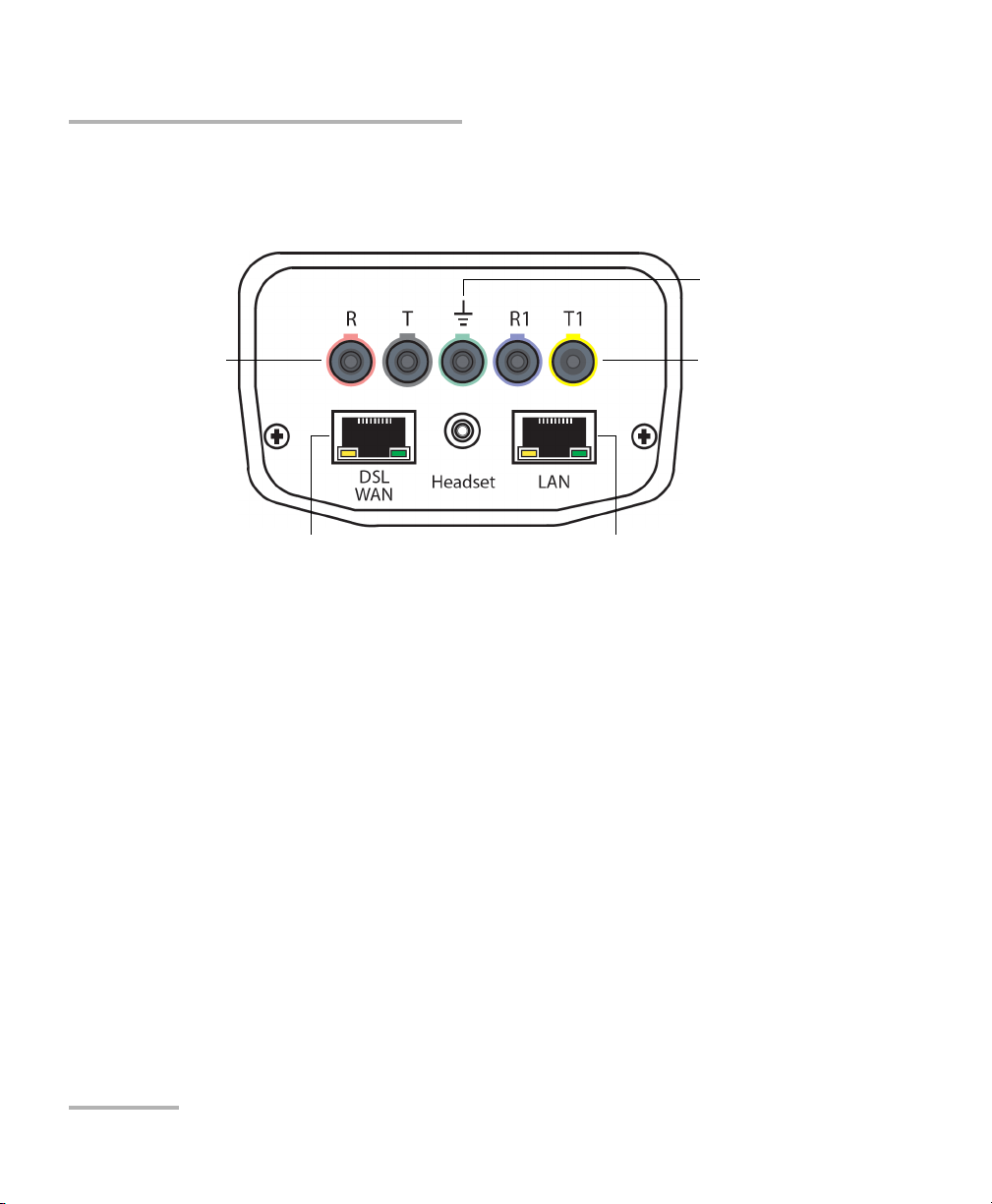
Introducing the Copper, VDSL2, ADSL2+ and IP Triple-Play Test Set
Primary tip/ring
3-pin connectors
Secondary tip/ring
3-pin connectors
LAN port for Ethernet
output
WAN port for Ethernet and
DSL input
Measuring ground
terminal
Cable Connections
Cable Connections
The graphic below shows the connectors on the AXS-200/635i device.
Note: When connecting a DSL cable to the WAN port, use the RJ-45 plug end of
the 26AWG cable provided with the unit. There is a 1500V maximum
transient voltage on telecom ports. Basic is needed for external telecom
circuits.
Note: When connecting to the LAN port, use only shielded Ethernet cables during
DSL testing.
4 AXS-200/635i
Page 13
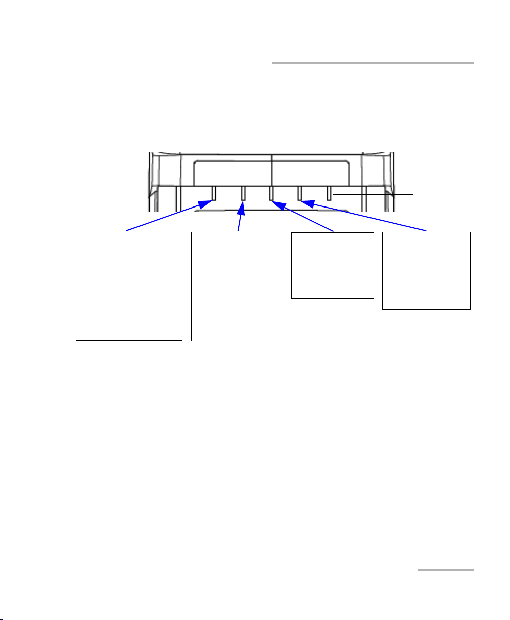
Introducing the Copper, VDSL2, ADSL2+ and IP Triple-Play Test Set
VOLTAGE DETECTED
Red indicates that a voltage
is detected on the line. This is
normal if the voice switch is
connected to the circuit
under test. If the circuit is
open, foreign voltage is
present - either DC (with
battery cross) or AC (induced
from electrical power lines.
PAS S/FAI L
Red indicates that test
results have failed the
thresholds.
Green indicates that test
results were evaluated
against the
customer-defined
thresholds and have
passed.
ERROR
Red indicates that
alarms/errors have
occurred at the DSL
and /or Ethernet
layers.
SYNC
Red indicates that
modems are starting to
negotiate or sync is lost.
Green indicates the link
is established
successfully.
Spare
LED Indicators
LED Indicators
The graphic below illustrates the LED indicators across the top front of the
AXS-200/635i unit.
Copper, VDSL2, ADSL2+ and IP Triple-Play Test Set 5
Electrical Safety Information
Do not use the unit outdoors in wet locations. For information about
equipment rating for temperature, environment, and power supply, refer to
the Safety Information chapter of the AXS-200 User Guide.
Page 14

Introducing the Copper, VDSL2, ADSL2+ and IP Triple-Play Test Set
ADSL2+ Basic Principles
ADSL2+ Basic Principles
ADSL2+ based testing requires an ATU-C (ADSL Transceiver Unit - Central
Office) that resides in a DSLAM (Digital Subscriber Line Access Multiplexer)
in the Central Office/Local Exchange. At the customer premises, there is an
ATU-R (ADSL Transceiver Unit - Remote) that interfaces with a user's PC.
The Copper, VDSL2, ADSL2+ and IP Triple-Play Test Set allows you to
emulate the ATU-R (customer’s ADSL modem). Once a connection is
established with the ATU-C in the DSLAM at the service provider’s central
office or remote DLC, the AXS-200/635i displays the connection rates for
the upstream and downstream directions of the ADSL2+ link.
VDSL2
Very high speed digital subscriber lines (VDSL) is a standard that allows
extremely high speed internet access over existing copper cables. The
VDSL2 standard increases the spectrum allocation up to 30 MHz for even
higher performance than its predecessor VDSL1, and allows speeds up to
100 Mbps symmetrical (both up and downstream). VDSL2 also calls for
support of applications such as multi-channel high definition TV (HDTV),
video on demand, video-conferencing, and VoIP using the existing copper
telephone line infrastructure. Along with that, it also calls for ATM, Ethernet,
and IP compatibility, as well as multimode implementations to permit
interoperability with existing ADSL equipment.
VDSL2 gives carriers the flexibility to start rapidly deploying VDSL2
networks and offer new broadband services including triple-play services HDTV, VoD, high-speed data, VoIP, high-speed Internet access, video
conferencing, virtual private networks (VPNs), PBX Extension, and video
surveillance - to compete with cable companies.
6 AXS-200/635i
Page 15
Introducing the Copper, VDSL2, ADSL2+ and IP Triple-Play Test Set
Navigating through the AXS-200/635i
Navigating through the AXS-200/635i
Use the following general instructions to navigate through the AXS-200/635i
menus and panes:
³ To navigate through the menu
items use the arrow keys or press
the corresponding test number on
the keypad.
³ To confirm a choice or open a
menu item press .
³ Most manual tests
automatically run when they
are selected from the menu.
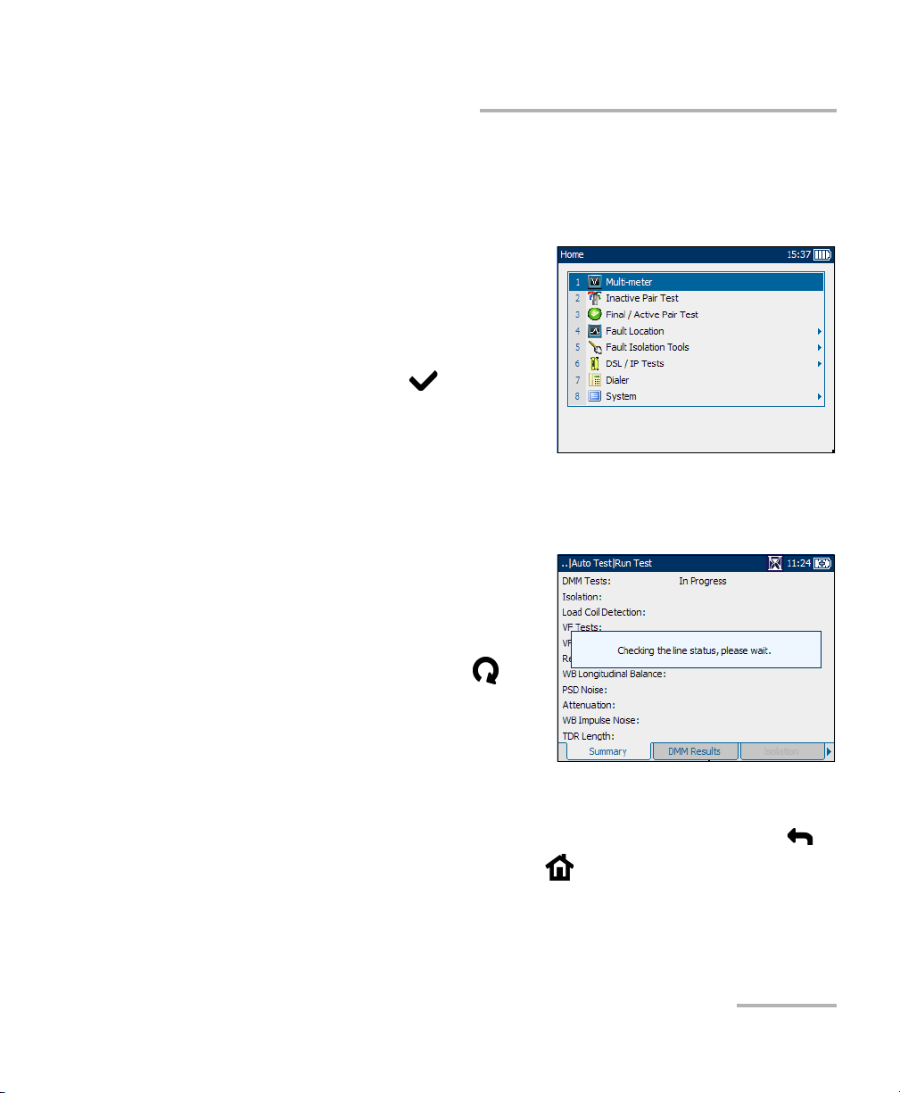
³ The rotating hour glass in the title bar indicates when a test is
running.
Note: For Fault Isolation Tools, the unit
checks for an active circuit at the
beginning of every manual and auto
test.
³ To start/stop a test, press .
³ To view the contents of the panes
or tabs, use the F1, F2, and
F3 keys. To view any available
additional tabs use the function arrow keys on either side of the F1 and
F3 keys.
³ To cancel an action or return to the previous item or pane, press .
³ To return to the home pane, press .
Copper, VDSL2, ADSL2+ and IP Triple-Play Test Set 7
Page 16
Introducing the Copper, VDSL2, ADSL2+ and IP Triple-Play Test Set
Conventions
Conventions
Before using the product described in this manual, you should understand
the following conventions:
WARNING
Indicates a potentially hazardous situation which, if not avoided,
could result in death or serious injury. Do not proceed unless you
understand and meet the required conditions.
CAUTION
Indicates a potentially hazardous situation which, if not avoided,
may result in minor or moderate injury. Do not proceed unless you
understand and meet the required conditions.
CAUTION
Indicates a potentially hazardous situation which, if not avoided,
may result in component damage. Do not proceed unless you
understand and meet the required conditions.
IMPORTANT
Refers to information about this product you should not overlook.
8 AXS-200/635i
Page 17
2 Getting Started with Fault
Isolation Tools
The AXS-200/635i is designed to test basic twisted pair quality, identify and
locate faults, perform advanced single-ended loop tests, and troubleshoot
noise and signal issues all the way up to 30 MHz in support of the VDSL2
standard. These measurements offer a quick and thorough method to
determine if the cable is capable of supporting xDSL technology. In
addition, it utilizes noise measurements, longitudinal balance tests, and
power spectral density tests to assist in the installation, maintenance, and
troubleshooting of copper cables.
Note: Tests can be accessed and run directly from the Home menu.
To access/run fault isolation tools:
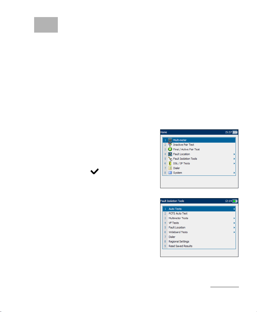
1. On the Home pane use the
up/down arrow keys to highlight
any one of the easy-access fault
isolation tools: Multi-meter,
Inactive Pair Test, Final/Active
Pair Test, or Fault Location, then
press .
OR
2. Select Fault Isolation Tools to
choose from a complete list of
tests.
Copper, VDSL2, ADSL2+ and IP Triple-Play Test Set 9
Page 18
Getting Started with Fault Isolation Tools
Dialer Function
Dialer Function
The Dialer function provides a dial-up path from the AXS-200/635i to
another tester (or quiet termination or silent switchman) through a
switched circuit network. DTMF transmission is enabled via the AXS-200
keypad allowing you to place and receive POTS calls. The dialer can be
accessed from the Home pane and is also integrated into individual test
screens to give you quick access to the manual dialer function, speed dial
and last dialed lists, without exiting the current test application.
Dialer
The Dialer menu item/tab allows you to use the unit as a telephone (with a
headset) and the AXS-200 keypad as a dialer keypad when the Dialer is
invoked, whether in the test results screens or through the separate
dedicated Dialer application. It goes off hook immediately when entered
from the menu or when switched from another tab.This allows you to
quickly check if the circuit under test has dial tone or is a digital service.
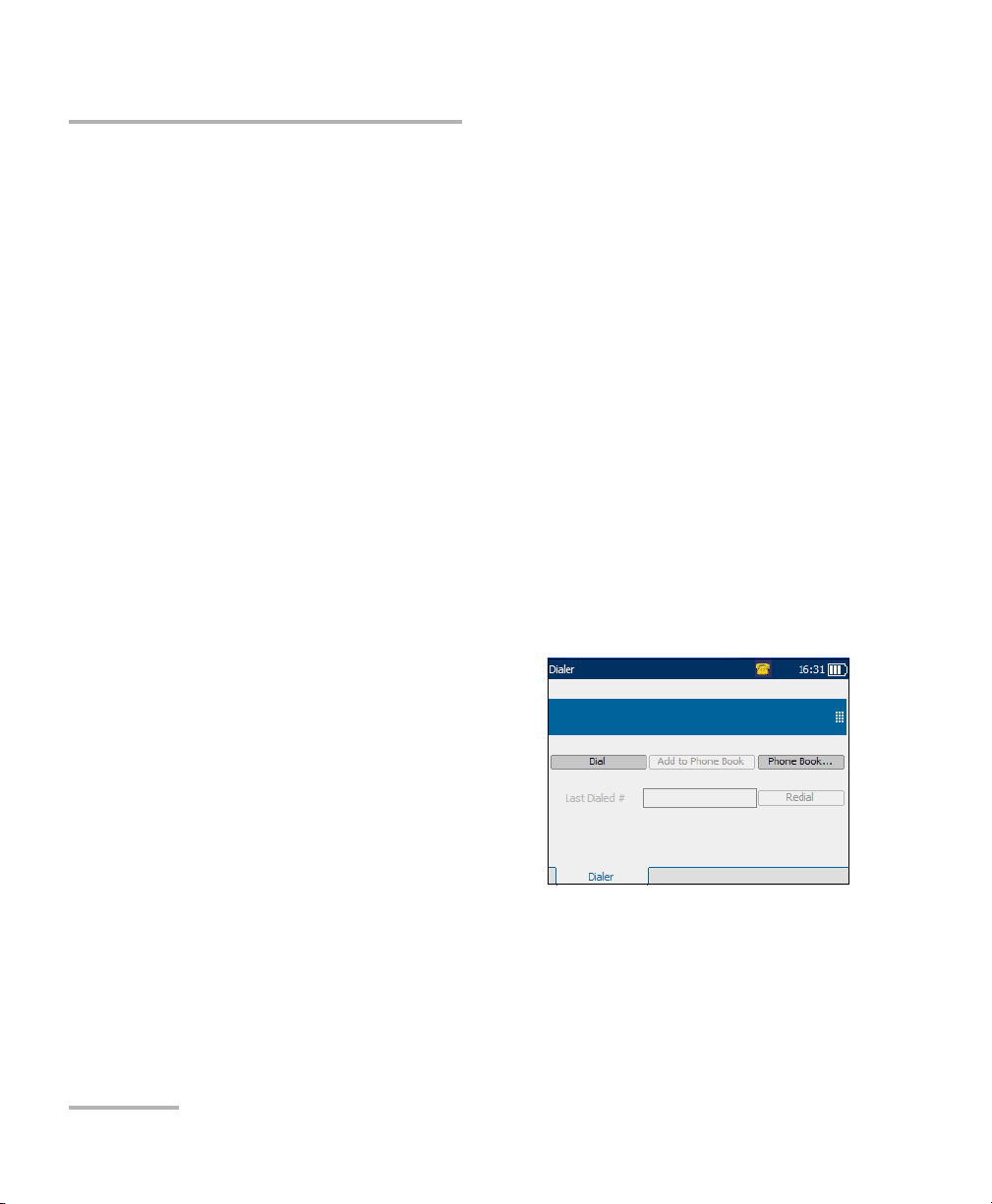
Each parameter and button are described below:
³ The edit box is where you enter
the phone number you wish to
dial. You can add this number to
the Phone Book by pressing the
Add to Phone Book button.
³ Dial button is enabled whether or
not there is a number present in
the edit box. If there is a number, it
will be dialed. If not, pressing the
Dial button will cause the unit to go off hook and a new placing a call
pane appears where you can manually dial a number from the keypad.
10 AXS-200/635i
Page 19
Getting Started with Fault Isolation Tools
Dialer Function
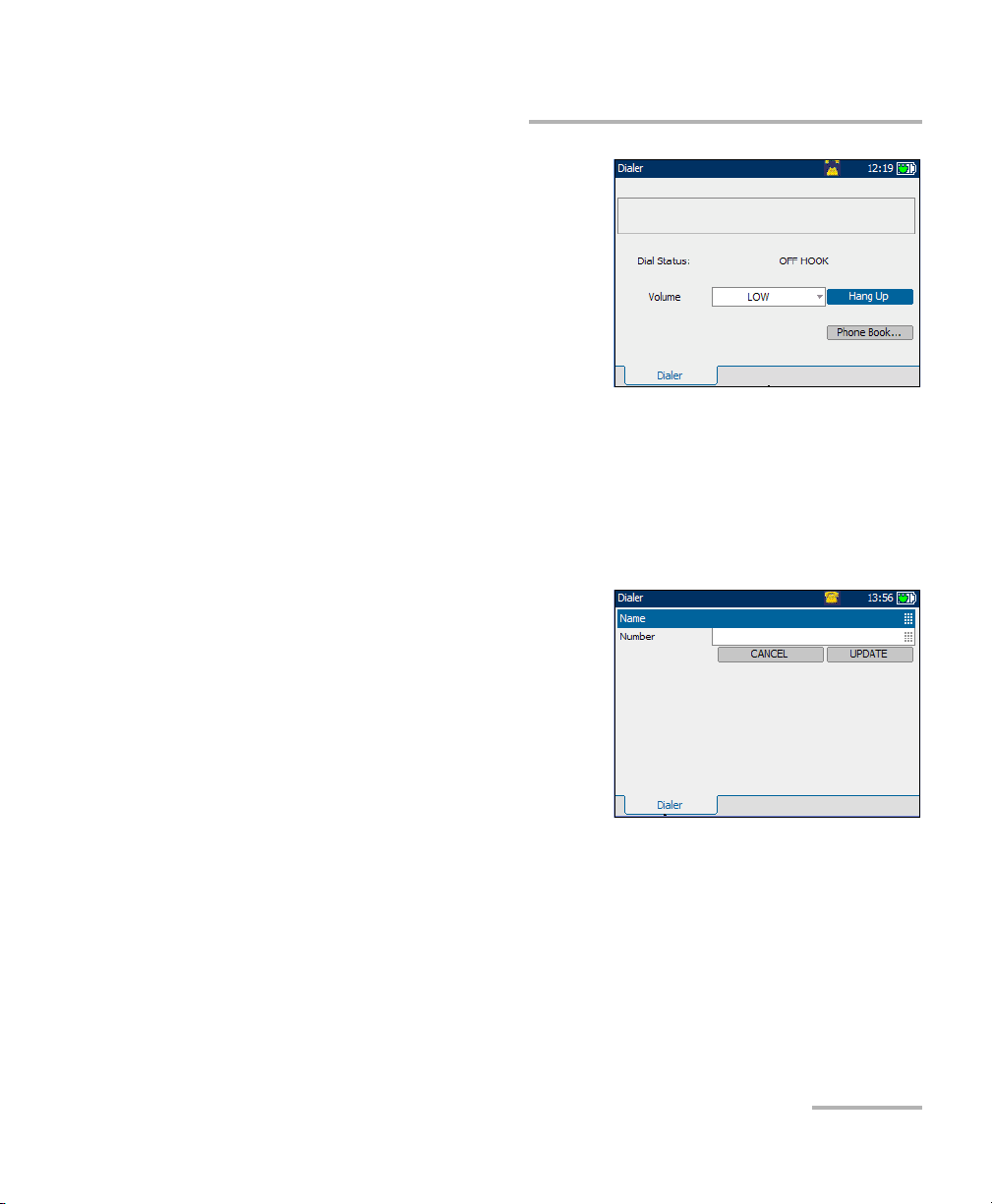
³ Dial Status displays the
progress of dialing such as
Dial Tone Detected,
No Dial Tone, or
Busy Tone Detected.
³ Volu me is used to set the
headset volume to LOW or
HIGH.
³ Hang Up button terminates
the call and you’ll be returned to the on-hook pane.
³ Phone Book... button invokes the list of numbers to dial and supports
30 commonly called names and numbers. Names can be up to 30
characters long and numbers up to 32 digits. When returning from the
Phone Book, the Dialer automatically dials the selected phone
number if it is in the off-hook state.
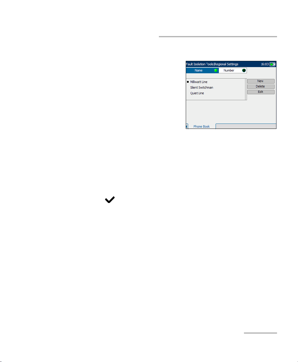
³ Add to Phone Book button enters
the number dialed into the Phone
Book by bringing up the
edit screen where you can add the
Name for the Number dialed and
save it. After pressing either the
CANCEL or UPDATE buttons, you’ll
be returned to the Dialer pane.
³ Last Dialed # lists up to 30 last
dialed numbers.
³ Redial button dials a selected phone number from the
Last Dialed # list.
³ Icon on title bar gives a live on-screen, graphical indication of on-hook
and off-hook status.
Copper, VDSL2, ADSL2+ and IP Triple-Play Test Set 11
Page 20

Getting Started with Fault Isolation Tools
Dialer Function
To select parameter values:
1. Press the up/down arrow keys to highlight the desired parameter.
2. Press to display the list or select the value.
3. Press the up/down arrow keys to highlight the desired value.
OR
4. Press the left arrow key to erase the existing value, and then use the
alphanumeric keypad to enter a value. To cancel the entry, press .
5. Press to accept the value.
12 AXS-200/635i
Page 21
Getting Started with Fault Isolation Tools
Dialer Function
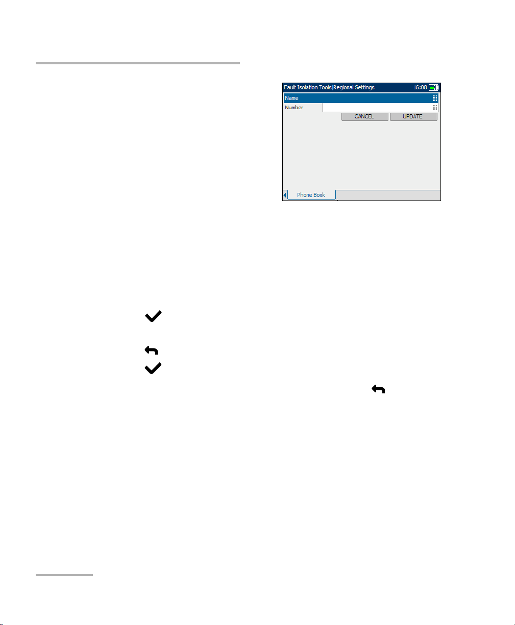
Phone Book
Phone Book provides you with a list of
saved names and numbers that will be
part of the Profile.
Each parameter and button is
described below:
³ Name displays the list box of
names in a Phone Book list.
³ Number displays the list box of
phone numbers in a Phone Book list.
³ List Box can display up to 30 names/numbers. Once the list box
reaches 30 entries the New button will be disabled. The Phone Book
has 3 predefined entries: Milliwatt Line, Silent Switchman, and Quiet
Line. These entries can be edited but not removed.
To select a name/number from the current list:
1. Press the up/down arrow keys to highlight the desired parameter.
2. Press to select the item.
This selection can be edited or removed. Once you leave this screen, the
selected name/number will be used to dial. All changes are automatically
saved into Phone Book.
³ New invokes the edit screen where a new name and number can be
entered then saved to the Phone Book list.
³ Delete removes the selected entry from the Phone Book list.
³ Edit invokes the edit screen where a name and number can be viewed
or changed.
Copper, VDSL2, ADSL2+ and IP Triple-Play Test Set 13
Page 22
Getting Started with Fault Isolation Tools
Dialer Function
On the edit screen, the following
controls are shown:
³ Name is the name, maximum 30
characters, assigned to the phone
number entered in the
Phone Book.
³ Number is the phone number,
maximum 32 digits including #,*
and comma.
³ CANCEL button returns you to the Phone Book screen without saving
any changes.
³ UPDATE button stores the Name and Number entered, in the
Phone Book.
To select and edit the controls:
1. Press the up/down arrow keys to highlight the desired entry and
press .
2. Use the alphanumeric keypad to enter a value. To cancel the entry,
press .
3. Press to accept the value.
4. To return from the Phone Book to the Dialer, press the The Dialer
automatically dials the selected phone number if it is in the off-hook
state.
14 AXS-200/635i
Page 23
Getting Started with Fault Isolation Tools
Regional Settings
Regional Settings
Before executing fault isolation tools, set up the software settings and
values for the cables. The AXS-200/635i allows you to save standard
parameter settings to different profiles and reuse them as needed.
To access Regional Settings:
From the Home pane, select Fault Isolation Tools, then Regional
Settings.
The following parameters are available to configure:
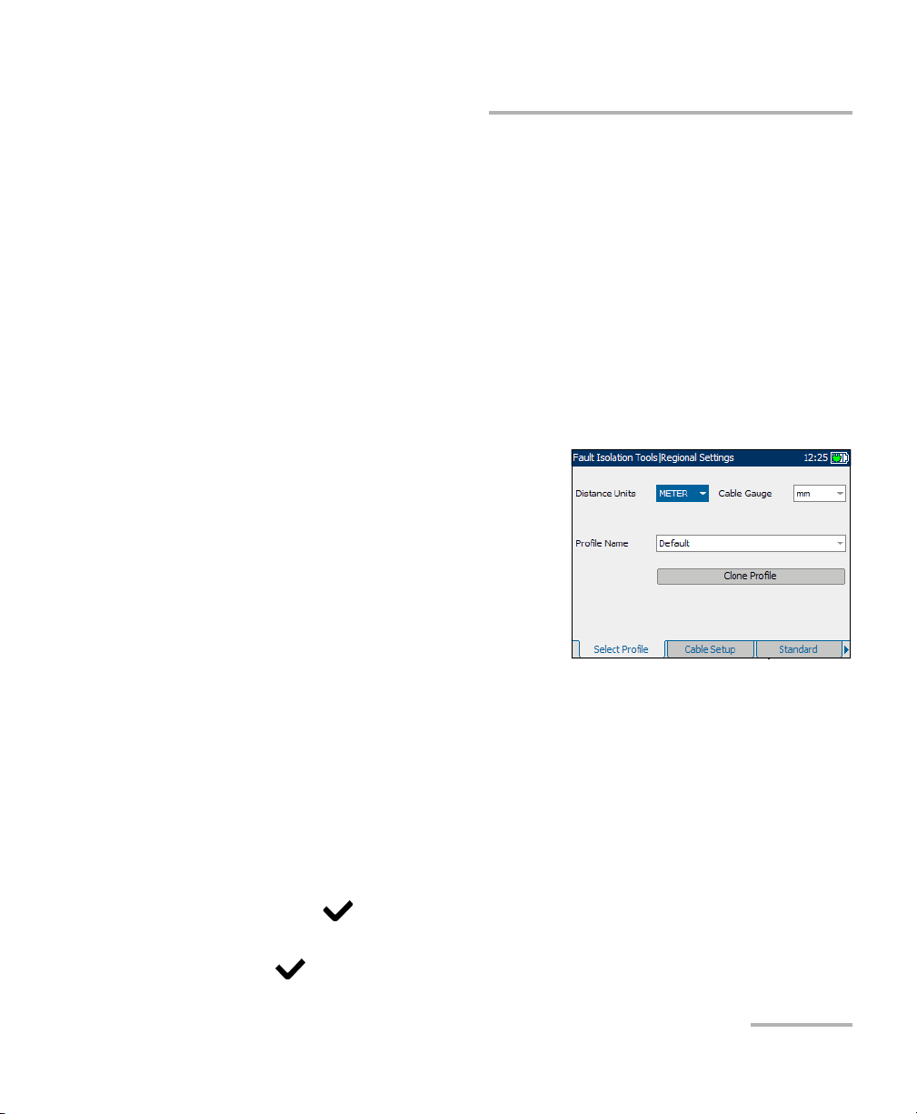
Select Profile
The Select Profile tab allows you to
configure the unit with specific
measurement values.
Each parameter is described below:
³ Distance Units are the units of
measurement for distances in
FEET or METER.
³ Cable Gauge is the gauge system
for measuring wire sizes in AWG (American Wire Gauge) units or mm
(metric wire size).
³ Profile Name is either Default or a list of all available profile file names
stored in the current directory.
³ Clone Profile allows you to copy an existing profile to a new one and
switch to use the new profile.
To select the parameter values:
1. Press the up/down arrow keys to highlight the desired parameter.
2. Press to display the list.
3. Use the up/down arrow keys to highlight the desired value, and press
to accept the value.
Copper, VDSL2, ADSL2+ and IP Triple-Play Test Set 15
Page 24
Getting Started with Fault Isolation Tools
Regional Settings
When you change the selections and press or , the
following actions should be performed:
1. If ProfileName selection is not Default then save modifications (if any)
into the current profile file and proceed with the selected action.
2. If ProfileName selection is Default and modification to the profile has
been made then enter the new name of the profile.
At power up, all settings are read from the last current profile.
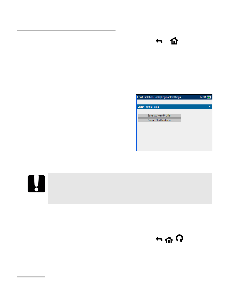
³ Enter Profile Name is the new
name of the profile.
To save modifications made to a
CustomProfile:
1. Select Save as New Profile and
create and save a new
CustomProfile name in the
current directory.
2. If the file with CustomProfile
name already exists in the current directory, you will be prompted to
overwrite it.
IMPORTANT
Changes to test parameters will be lost if the unit is turned off
without first saving them to a default or custom profile. The unit
can also be left in suspend mode to avoid loss of test parameters.
To cancel modifications made to a CustomProfile:
1. Select Cancel Modifications and reload the current profile with the
default profile.
2. Proceed with the previously selected action ( , , ).
16 AXS-200/635i
Page 25
Getting Started with Fault Isolation Tools
Regional Settings
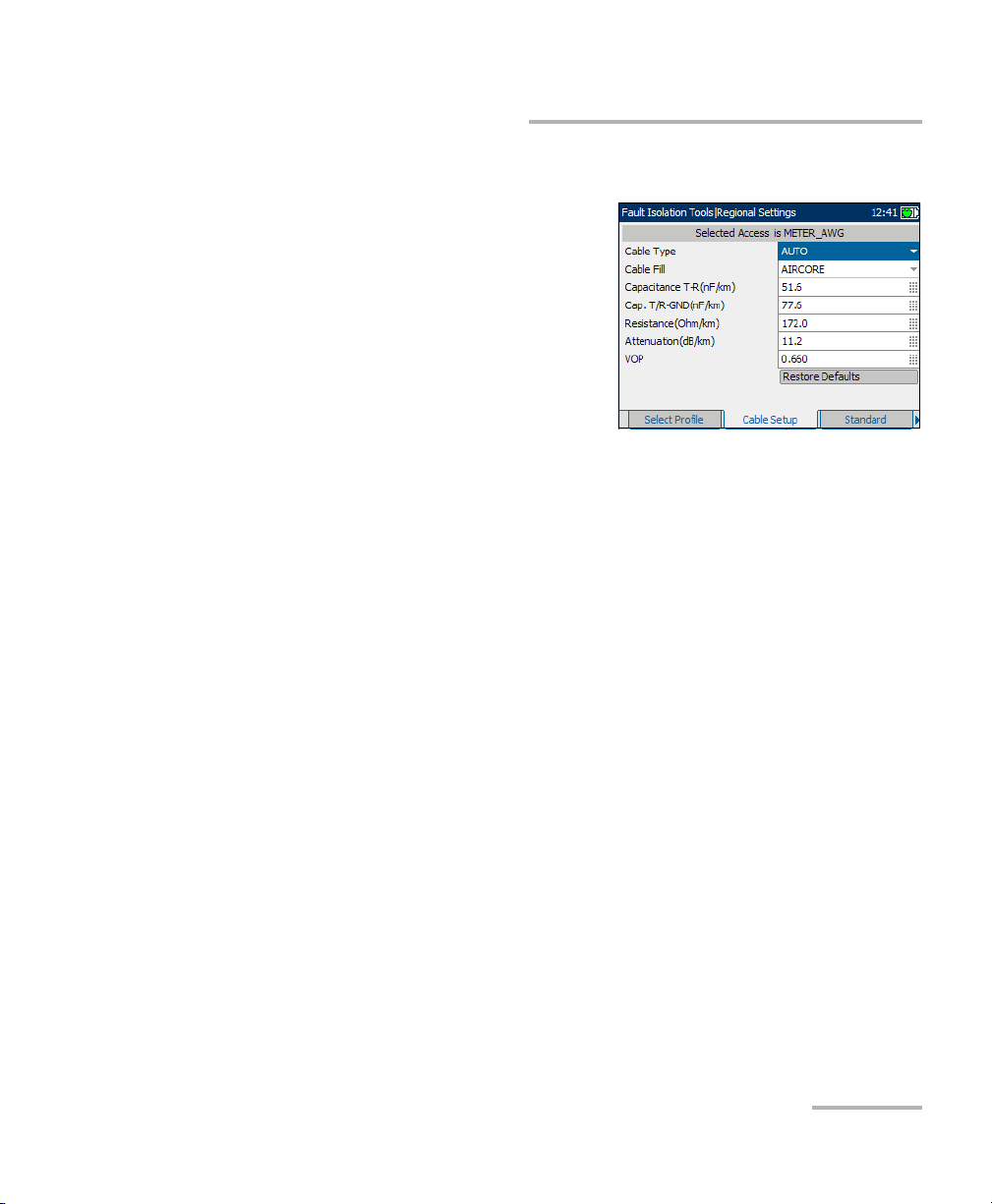
Cable Setup
The Cable Setup tab allows you to
configure parameter values for the
cable.
Each parameter and button is
described below:
³ Cable Type defines the gauge of
the cable in use. If wire gauge is
measured in American Wire
Gauge (AWG) units, the available
choices are: AUTO, 19 AWG, 22 AWG, 24 AWG, or 26 AWG. For mm
gauge wire, the available choices are: AUTO, 0.32 mm, 0.40 mm,
0.50 mm, 0.60 mm, 0.65 mm, 0.80 mm, 0.90 mm, or 1.20 mm.
³ Cable Fill allows you to select the type of material the cable can be
filled with. Changing the selection to AIRCORE, JELLY, PULP, 5PR, or
2PR influences the cable capacitance per length, automatically
updating the Cap. T/R-GND field.
³ Capacitance T-R (nF/km or nF/mi) allows you to specify a value for the
capacitance per length constant.
³ Cap. T/R-GND (nF/km or nF/mi) allows you to specify a value for the
capacitance per length to ground constant.
³ Resistance (Ohm/km or Ohm/mi) allows you specify a value for the
resistance constant of the cable.
³ Attenuation (dB/km or dB/mi) allows you to specify a value for the
reduction in signal strength or insertion loss of the cable.
³ VOP allows you to set the velocity of propagation for the cable as a
ratio of the speed of light. Enter a value between 0.400 and 0.999.
³ Restore Defaults allows you to reset cable parameters for the selected
cable to the standard default values.
Copper, VDSL2, ADSL2+ and IP Triple-Play Test Set 17
Page 26

Getting Started with Fault Isolation Tools
Regional Settings
To select parameter values:
1. Press the up/down arrow keys to highlight the desired parameter.
2. Press to display the list or select the value.
3. Press the up/down arrow keys to highlight the desired value.
OR
4. Press the left arrow key to erase the existing value, and then use the
alphanumeric keypad to enter a value. To cancel the entry, press .
5. Press to accept the value.
To reset default cable values:
1. Press the up/down arrow keys to highlight Cable Type.
2. Press to display the list.
3. Press the up/down arrow keys to highlight the desired cable type, then
press to accept the selection.
4. Use the up/down arrow keys to highlight the Restore Defaults button,
then press . The selected cable’s default values are restored.
18 AXS-200/635i
Page 27
Getting Started with Fault Isolation Tools
Regional Settings
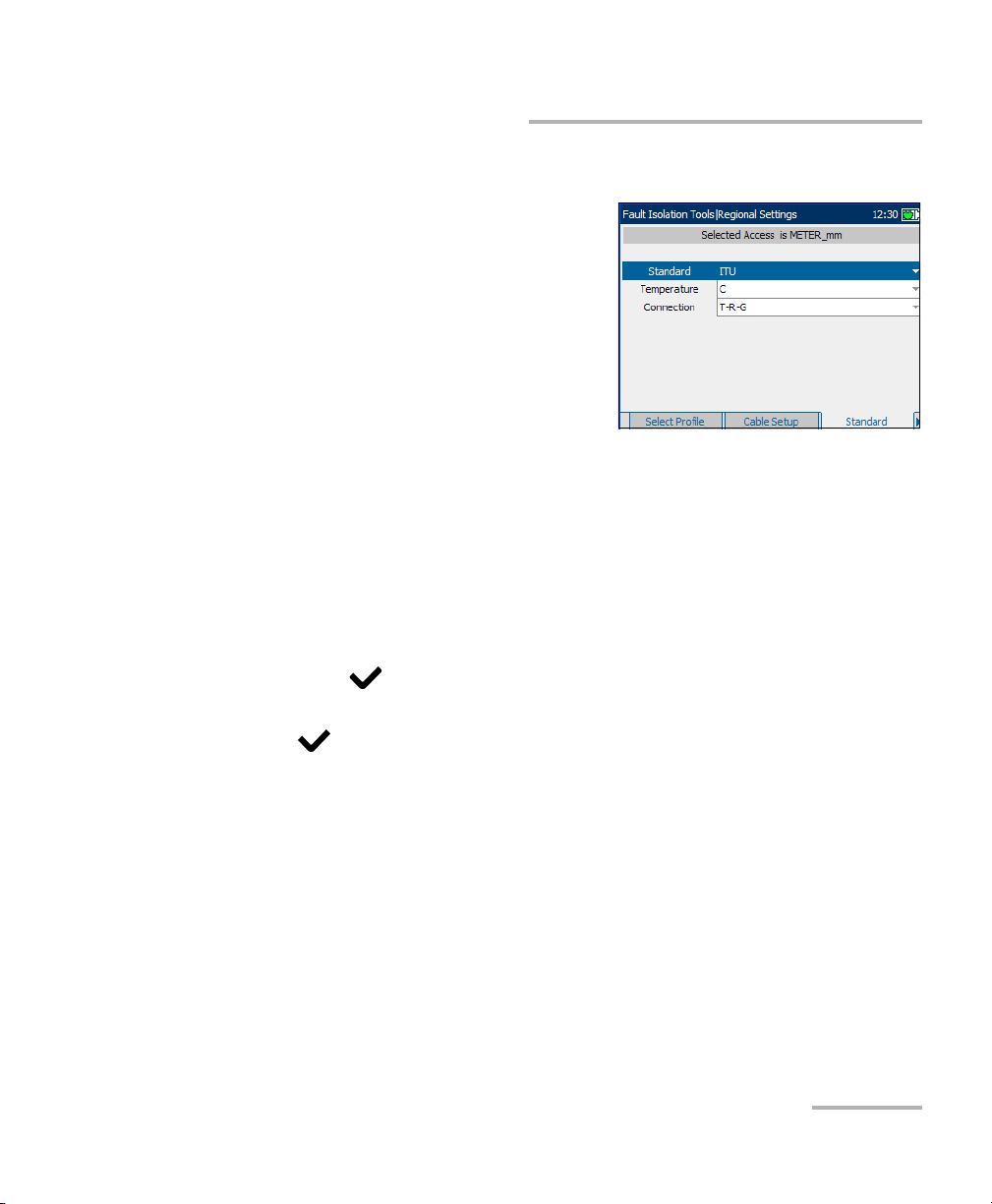
Standard
The Standard tab allows you to set
unit parameter values for the selected
profile composed of current Distance
Units and Cable Gauge.
³ Standard allows you to specify if
the fault isolation tools should
conform to the ITU (International
Telecommunication Union) or
ANSI (American National
Standards Institute) standard.
³ Tem pe ra tu re allows you to specify the units of measurement for
temperature in F (Fahrenheit) or C (Celsius).
³ Connection allows you to specify the default type of cable connections
as T-R-G or A-B-E.
To select the parameter values:
1. Press the up/down arrow keys to highlight the desired parameter.
2. Press to display the list.
3. Use the up/down arrow keys to highlight the desired value, and press
to accept the value.
Copper, VDSL2, ADSL2+ and IP Triple-Play Test Set 19
Page 28
Getting Started with Fault Isolation Tools
Saving Results
Saving Results
You can save any of your results after running and viewing a test performed
with the AXS-200/635i, in either text or graphical format. Each fault isolation
tool includes a Save Results tab to do so.
Press the F1, F2, or F3 key to view this tab, or use the function
arrow keys on either side of the F1 and F3 keys to access it.
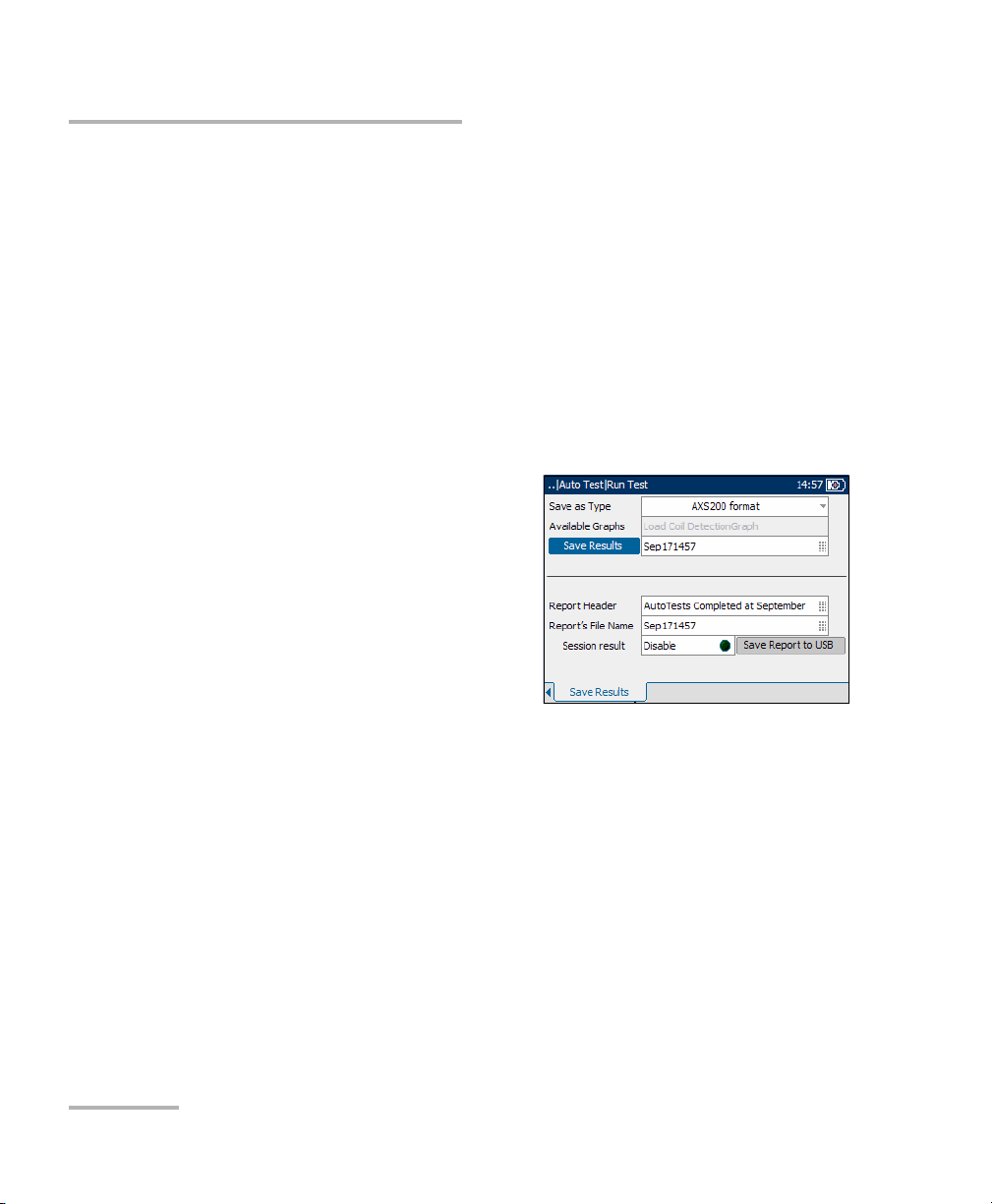
Save Results
The Save Results tab allows you to save your test results to a file or to an
HTML report.
Each entry on the pane is described as
follows:
³ Save as Type lists the following
formats to save your test results:
³ AXS200 format is a binary file
format with ext *.dat. This
format can be opened only on
an AXS200 unit. The Available
Graphs list box will be
unavailable in this case.
³ *.csv saves only graphical results.Textual results must be formatted
as a comma-separated values table for easy importation to Excel.
Results are saved to USB.
³ *.gif stands for graphics interchange format and is one of the most
common file formats for graphic images on the World Wide Web.
Results are saved to USB.
³ *.bmp saves graphical results in a bitmap file format. Results are
saved to USB.
³ *.xml saves your data in a common language format to share on
the Web. Results are saved to USB.
20 AXS-200/635i
Page 29

Getting Started with Fault Isolation Tools
Saving Results
³ Available Graphs is enabled only if the selected format under
Save as Type is *.gif, *.csv, or *.bmp.The selection of graphs available
are: Load Coil Detection, VF Power Influence, PSD Noise,
WB Spectral Detective, WB Impulse Noise Histogram, Attenuation,
WB Long. Balance, Loop Mapper, TDR, and Auto Test. For a test that
does not have a graph, this list box is unavailable.
³ Save Results button saves the test results in internal or external
memory (depending on the Save as Type format).
³ Filename is the current date and time stamp plus you can enter any
name. If it already exists, you will be prompted to overwrite the existing
file.
³ Report Header is where you can enter any comment. The initial value
is the current test followed by the date and time stamp.
³ Report’s File Name is where you can enter any name for the HTML
filename. If the name already exists, you will be prompted to overwrite
the existing file.The default extension is .html.
The default name is generated from the current time.
³ Session result creates and saves the report for single test results when
disabled, or appends multiple results in one report when enabled.
³ Save Report to USB button saves the results to an HTML report. If a
USB memory stick is not inserted, the following warning dialogue box
appears: USB device is not detected.
³ Append to Report button appears only if Session result is Enable,
and creates an HTML report for the current test in internal memory.
Copper, VDSL2, ADSL2+ and IP Triple-Play Test Set 21
Page 30

Getting Started with Fault Isolation Tools
Saving Results
To set parameter values and save results:
1. Press the left/right and up/down arrow keys to highlight the desired
parameter.
2. Press to display the list or select the value.
3. Press the up/down arrow key to highlight the desired value.
OR
4. Press the left arrow key to erase the existing value, and then use the
alphanumeric keypad to enter a value. To cancel the entry, press .
5. Press to accept the value.
22 AXS-200/635i
Page 31
Getting Started with Fault Isolation Tools
Reading Saved Results
Reading Saved Results
You can view any of your saved results with the Copper, VDSL2, ADSL2+
and IP Triple-Play Test Set, by highlighting the Read Saved Results menu
item from the Fault Isolation Tools pane, and pressing .
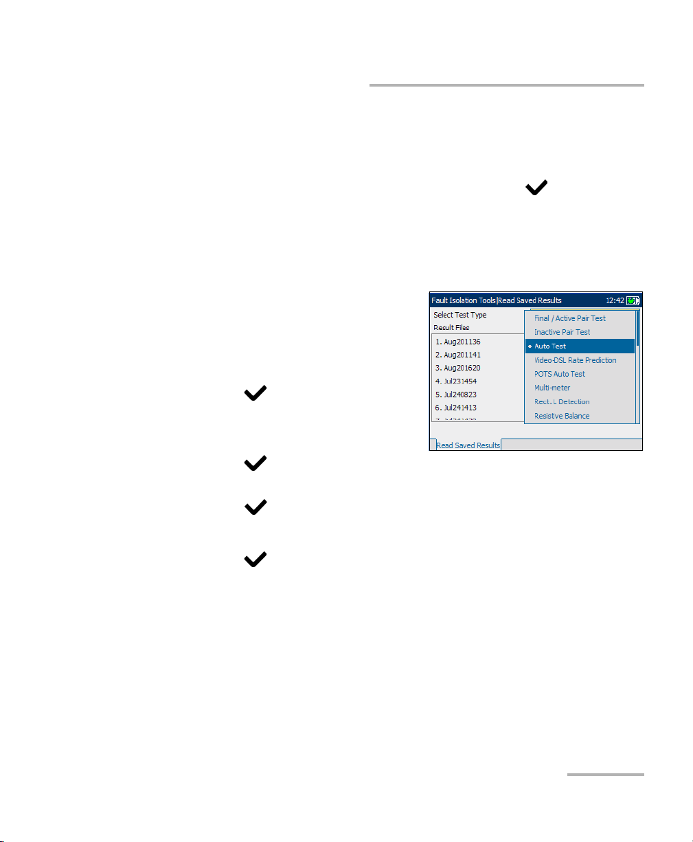
Read Saved Results
The Read Saved Results tab allows you to select a test type and view the
results of all the files previously saved.
Sele ct Test Typ e provides a list of all
the fault isolation tools test types
available for you to select for viewing.
To open previously saved test
results:
1. Press to open the list.
2. In the list, press the up/down
arrows to select the test type.
3. Press to confirm the selection.
4. Press the down arrow to activate the Result Files list box and
press to display the list of available files.
5. Press the up/down arrows to select the desired result file.
6. Press to view the selection.
Copper, VDSL2, ADSL2+ and IP Triple-Play Test Set 23
Page 32

Page 33

3Auto Tests
The auto test function allows you to automatically run tests used in
pre-qualification, installation, and maintenance of different circuit types
from POTS to VDSL2. Auto tests include a range of different tests that
compare measured results against stored threshold values to provide pass
or fail results. The results are displayed in both text and graphical format.
To access Auto Tests:
1. From the Home pane use the up/down arrow keys to highlight Fault
Isolation Tools and press .
2. Highlight Auto Tests and press .
The following tests are included in the auto test function:
³ CQ Auto Test
³ Inactive Pair Test
³ Final/Active Pair Test
³ Video-DSL Rate Prediction
Configuring CQ Auto Tests
Parameters for auto test configuration are on the CQ Auto Test pane tabs.
To view CQ auto test
configuration tabs:
1. From the CQ Auto Test pane use
the up/down arrow keys to
highlight Test Configuration, and
press .
2. Press the F1, F2, or F3 key to view
the various tabs. To view any
available additional tabs, use the
function arrow keys on either side of the F1 and F3 keys.
Copper, VDSL2, ADSL2+ and IP Triple-Play Test Set 25
Page 34

Auto Tests
Configuring CQ Auto Tests
Test List 1
The Test L ist 1 tab allows you to select the types of tests to include in the
auto test function.
The following tests are available:
³ AC/DC Voltage detects AC RMS
and DC voltages in the line. Toggle
between Enable and Disable.
³ AC/Loop Current checks for AC
RMS and loop currents in the line.
Toggle between Enable and
Disable.
³ Shorts Meter measures resistances between the wires and to ground.
It is also used to identify possible faults, and to measure the resistance
of the twisted pair cable for estimating loop length. Toggle between
Enable and Disable.
³ Opens Meter measures the capacitance of the cable for estimating
loop length. Toggle between Enable and Disable.
³ Metallic Insulation measures the quality of insulation or sheathing for
the copper pairs.
³ Load Coil Detection detects the presence of load coils in the line.
Toggle between Enable and Disable.
³ Power Influence measures the effects that 50 Hz and 60 Hz powerline
(AC Mains) interference has on the circuit under test. Toggle between
Enable and Disable.
³ Longitudinal Balance is very useful in identifying loops that will suffer
from crosstalk. Toggle between Enable and Disable.
³ Noise Metallic measures VF noise in the line. Toggle between Enable
and Disable.
26 AXS-200/635i
Page 35

Auto Tests
Configuring CQ Auto Tests
³ VF Impulse Noise measures the random occurrences of energy spikes
in the voice frequency range that have random amplitude and spectral
content.
To select tests:
1. Press the up/down arrow keys to highlight a desired test.
2. Press to toggle between Enable and Disable.
3. Select other tests as required.
Copper, VDSL2, ADSL2+ and IP Triple-Play Test Set 27
Page 36

Auto Tests
Configuring CQ Auto Tests
Test List 2
The Test List 2 tab allows you to select
additional tests to include in the auto
test function.
The following additional tests are
available:
³ VF Receive Tone measures the
level and frequency of the
incoming voice signal.
³ WB Receive Tone measures the level and frequency of the incoming
wideband signal.
Note: The VF and WB Receive Tone tests are mutually exclusive. When one test is
enabled, the other is automatically disabled.
³ WB Longitudinal Balance verifies that the wideband longitudinal
balance ratios comply with applicable standards.
³ PSD Noise measures power spectral density noise.
³ Attenuation measures the amount of reduction in signal strength.
³ WB Impulse Noise measures the irregular occurrences of energy
spikes in the wideband range that have random amplitude and
spectral content.
³ TDR test identifies and locates all types of faults as well as bridge taps
(multiple appearances) and load coils.
To s el e ct te st s :
1. Press the up/down arrow keys to highlight a desired test.
2. Press to toggle between Enable and Disable.
3. Select other tests as required.
28 AXS-200/635i
Page 37

Auto Tests
Configuring CQ Auto Tests
Common Parameters
The Common Param. tab allows you to
set up parameters common to all tests
in the auto test function.
Each parameter is described below:
³ Cable Type defines the gauge of
the cable in use. If wire gauge is
measured in AWG units, the
available choices are: AUTO,
19 AWG, 22 AWG, 24 AWG, or
26 AWG. For mm gauge wire, the available choices are: AUTO,
0.32 mm, 0.40 mm, 0.50 mm, 0.60 mm, 0.80 mm, 0.90 mm, or
1.20 mm.
³ Tem pe ra tu re specifies the temperature of the cable under test in
either F (Fahrenheit) or C (Celsius) units.
³ Isolation Test Time(sec) specifies the duration of the isolation test.
³ Input Impedance displays the input impedance in the loop. The
available choices are: >1 MOhm, 100 KOhm.
To set parameter values:
1. Press the up/down arrow keys to highlight the desired parameter.
2. Press to display the list or select the value.
3. Press the up/down arrow keys to highlight the desired value.
OR
4. Press the left arrow key to erase the existing value, and then use the
alphanumeric keypad to enter a value. To cancel the entry, press .
5. Press to accept the value.
Copper, VDSL2, ADSL2+ and IP Triple-Play Test Set 29
Page 38

Auto Tests
Configuring CQ Auto Tests
VF Test Parameters
The VF Parameters tab allows you to
set up parameters used in the voice
frequency tests.
Each parameter is described below:
³ Noise Metallic Filter defines the
level of voice frequency noise
filtering. If the ANSI standard is
used, the available choices are:
NONE, C-MESSAGE, CNOTCHED,
3kHzFLAT, D-FILTER or 15 kHz. If the ITU standard is used, the
available choices are: NONE, PSOPHOMETRIC, P-NOTCHED,
3kHzFLAT, D-FILTER or 15 kHz.
³ VF Termination defines if the unit uses normal test impedance
termination or high bridging impedance when the cable is active or
terminated by other external equipment. For normal test termination
select TERMINATED, otherwise select BRIDGING.
³ Imp. Noise Filter defines the type of impulse noise filtering to use. If
ANSI standard is used, the available choices are: NONE, C-MESSAGE,
CNOTCHED, 3kHzFLAT, D-FILTER or 15 kHz. For the ITU standard,
the choices are: NONE, PSOPHOMETRIC, P-NOTCHED, 3kHzFLAT,
D-FILTER or 15 kHz.
³ Low Threshold(dBm) defines the low threshold limits for impulse
noise. Specify a value between -40 and 0.
³ Separation(dB) defines the level difference (in dB) between the low,
the mid and high thresholds. Specify a value between 1 and 6 dB.
³ Imp. Noise Measure. Time defines the time duration to measure
impulse noise. The available choices are: 1 minute, 5 minutes,
10 minutes, 15 minutes, 60 minutes, or 24 hours.
30 AXS-200/635i
Page 39

Auto Tests
Configuring CQ Auto Tests
To set parameter values:
1. Press the up/down arrow keys to highlight the desired parameter.
2. Press to display the list or select the value.
3. Press the up/down arrow keys to highlight the desired value.
OR
4. Press the left arrow key to erase the existing value, and then use the
alphanumeric keypad to enter a value. To cancel the entry, press .
5. Press to accept the value.
Copper, VDSL2, ADSL2+ and IP Triple-Play Test Set 31
Page 40
Auto Tests
Configuring CQ Auto Tests
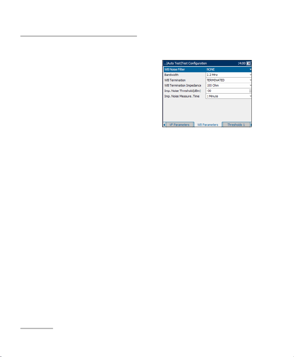
WB Test Parameters
The WB Parameters tab allows you to
set up parameters used in the
wideband tests.
Each parameter is described below:
³ WB Noise Filter defines the level
of wideband noise filtering. The
available choices are: NONE,
50 kbit, ISDN-E, HDSL-F, ADSL-G,
ADSL, ADSL2+, VDSL, VDSL2-8,
VDSL2-12, VDSL2-17, or VDSL2-30.
Note: VDSL2-x filters are only available if VDSL2 is enabled in the software
options.
³ Bandwidth specifies the frequency range for the test: 2.2 MHz,
12 MHz, 17 MHz, or 30 MHz.
Note: Frequency bands in excess of 2.2 MHz are only displayed if VDSL2 is
enabled in the software options.
³ WB Termination defines if the unit uses normal test impedance
termination or high bridging impedance when the cable is active or
terminated by other external equipment. For normal test termination
select TERMINATED, otherwise select BRIDGING.
³ WB Termination Impedance defines the impedance of the dummy
load connected to the line. Select one of the following: 100 Ohm or
135 Ohm.
³ Imp. Noise Threshold(dBm) is the maximum impulse noise level.
Specify a value between -50 and 0 (-40 and 0 if any filter applied).
³ Imp. Noise Measure. Time defines the time duration to measure
impulse noise. The available choices are: 1 minute, 5 minutes,
10 minutes, 15 minutes, 60 minutes, or 24 hours.
32 AXS-200/635i
Page 41

Auto Tests
Configuring CQ Auto Tests
To set parameter values:
1. Press the up/down arrow keys to highlight the desired parameter.
2. Press to display the list or select the value.
3. Press the up/down arrow key to highlight the desired value.
OR
4. Press the left arrow key to erase the existing value, and then use the
alphanumeric keypad to enter a value. To cancel the entry, press .
5. Press to accept the value.
Copper, VDSL2, ADSL2+ and IP Triple-Play Test Set 33
Page 42

Auto Tests
Configuring CQ Auto Tests
Thresholds 1
The Thresholds 1 tab allows you to set
threshold values for the auto tests.
Each parameter is described below:
³ Max. AC Voltage T-R (V) defines
the maximum AC threshold
voltage for the T-R leg of the circuit.
Specify a value between 1 and 30.
³ Max. AC Voltage to GND (V)
defines the maximum AC threshold voltage to ground for the circuit.
Specify a value between 1 and 30.
³ Max. DC Voltage T-R (V) defines the maximum DC threshold voltage
for the T-R leg of the circuit. Specify a value between 1 and 400.
³ Max. DC Voltage to GND (V) defines the maximum DC threshold
voltage to ground for the circuit. Specify a value between 1 and 400.
³ Min. Resistance T-R(MOhm): defines the minimum threshold
resistance for the T-R leg of the circuit. Specify a value between
0 and 999.
³ Min. Resistance T-G(MOhm) defines the minimum threshold
resistance for the T-G leg of the circuit. Specify a value between
0 and 999.
³ Min. Resistance R-G(MOhm) defines the minimum threshold
resistance for the R-G leg of the circuit. Specify a value between
0 and 999.
34 AXS-200/635i
Page 43

Auto Tests
Configuring CQ Auto Tests
To set a threshold value:
1. Press the up/down arrow keys to highlight the desired parameter.
2. Press to select the value.
3. Press the left arrow key to erase the existing value, and then use the
alphanumeric keypad to enter a value. To cancel the entry, press .
4. Press to accept the value.
Copper, VDSL2, ADSL2+ and IP Triple-Play Test Set 35
Page 44
Auto Tests
Configuring CQ Auto Tests
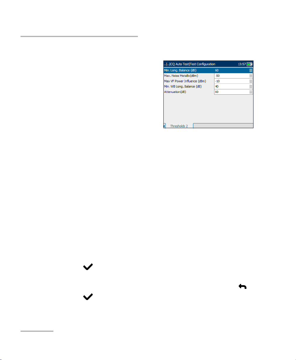
Thresholds 2
The Thresholds 2 tab allows you to set
additional threshold values.
Each parameter is described below:
³ Min. Long. Balance(dB) defines
the minimum voice frequency
threshold longitudinal balance
level. Specify a value between
10 and 80.
³ Max. Noise Metallic (dBm) defines the maximum threshold RMS
noise energy level. Specify a value between -90 and 10 if the ITU
standard is used. Specify a value between 0 and 100 if the ANSI
standard is used.
³ Max. VF Power Influence (dBm) defines the maximum threshold
power influence level on the circuit. Specify a value between
-90 and 20 if the ITU standard is used. Specify a value between
0 and 110 if the ANSI standard is used.
³ Min. WB Long. Balance(dB) defines the minimum threshold
wideband longitudinal balance level. Specify a value between
10 and 80.
³ Attenuation(dB) defines the threshold wideband attenuation level.
Specify a value between 0 and 80.
To set a threshold value:
1. Press the up/down arrow keys to highlight the desired parameter.
2. Press to select the value.
3. Press the left arrow key to erase the existing value, and then use the
alphanumeric keypad to enter a value. To cancel the entry, press .
4. Press to accept the value.
36 AXS-200/635i
Page 45

Auto Tests
Running CQ Auto Tests and Viewing Results
Running CQ Auto Tests and Viewing Results
Auto test results are located on the CQ Auto Test pane tabs.
To run auto tests and view results:
1. From the CQ Auto Test pane use
the up/down arrow keys to
highlight Run Test, and press .
2. Press the F1, F2, or F3 key to view
the various tabs. To view any
available additional tabs, use the
function arrow keys on either side
of the F1 and F3 keys.
Summary
The Summary tab displays the overall
PASS or FAIL status of all tests selected
for auto testing.
Copper, VDSL2, ADSL2+ and IP Triple-Play Test Set 37
Page 46

Auto Tests
Running CQ Auto Tests and Viewing Results
Multi-meter Results
The Multi-meter Results tab displays
the measured values and pass or fail
status of each digital multi-meter test.
Metallic Insulation
The Metallic Insulation tab displays
the measured Resistance values from
the isolation test.
Load Coil
The Load Coil tab displays the number
of load coils in the line, and measured
values from the load coil detection test
in graphical form.
To move the screen pointer:
Press the left/right arrow keys to move
the screen pointer. The pointer value
updates dynamically.
38 AXS-200/635i
Page 47

Running CQ Auto Tests and Viewing Results
VF Tests
The VF Tests tab displays the
measured values and PASS or FAIL
status of the voice frequency tests.
VF Impulse Noise
The VF Impulse Noise tab displays the
measured values from the voice
frequency impulse noise tests.
Auto Tests
Receive Tone
The Receive Tone tab displays the
current received frequency and level
values of the received tone.
Copper, VDSL2, ADSL2+ and IP Triple-Play Test Set 39
Page 48

Auto Tests
Running CQ Auto Tests and Viewing Results
WB Longitudinal Balance
The WB Long. Balance tab displays in
graphical form the measured values
from the wideband longitudinal
balance tests.
The list and buttons on the tab are
described below:
³ (Zoom function List) allows you to
select the desired zoom function
Horizontal Zoom or Vertical
Zoom. The selected function is displayed in the box.
³ Zoom In allows you to increase the level of zoom for the selected
zoom function.
³ Zoom Out allows you to reduce the level of zoom for the selected
zoom function.
To zoom in or out:
1. Press to display a list of zoom functions.
2. Press the up/down arrow keys to highlight the desired zoom function.
3. Press to select the zoom function.
4. Use the left/right arrow keys to highlight the Zoom In or Zoom Out
button as required, then press .
The graphical display zooms in or out accordingly.
5. Press repeatedly to continue zooming.
To move the screen pointer:
Press the left/right arrow keys to move the screen pointer. The pointer
value updates dynamically.
40 AXS-200/635i
Page 49

Auto Tests
Running CQ Auto Tests and Viewing Results
PSD Noise
The PSD Noise tab displays the RMS
Noise value from the power spectral
density (PSD) noise tests in text and
graphical form.
The list and buttons on the tab are
described below:
³ (Zoom function List) allows you to
select the desired zoom function:
Horizontal Zoom or Vertical
Zoom. The selected function is displayed in the box.
³ Zoom In allows you to increase the level of zoom for the selected
zoom function.
³ Zoom Out allows you to reduce the level of zoom for the selected
zoom function.
To zoom in or out:
1. Press to display a list of zoom functions.
2. Press the up/down arrow keys to highlight the desired zoom function.
3. Press to select the zoom function.
4. Use the left/right arrow keys to highlight the Zoom In or Zoom Out
button as required, then press .
The graphical display zooms in or out accordingly.
5. Press repeatedly to continue zooming.
To move the screen pointer:
Press the left/right arrow keys to move the screen pointer. The pointer
value updates dynamically.
Copper, VDSL2, ADSL2+ and IP Triple-Play Test Set 41
Page 50

Auto Tests
Running CQ Auto Tests and Viewing Results
Attenuation
The Attenuation tab displays in
graphical form the cable length value
from attenuation tests.
The list and buttons on the tab are
described below:
³ (Zoom function List) allows you to
select the desired zoom function:
Horizontal Zoom or Vertical
Zoom. The selected function is
displayed in the box.
³ Zoom In allows you to increase the level of zoom for the selected
zoom function.
³ Zoom Out allows you to reduce the level of zoom for the selected
zoom function.
To zoom in or out:
1. Press to display a list of zoom functions.
2. Press the up/down arrow keys to highlight the desired zoom function.
3. Press to select the zoom function.
4. Use the left/right arrow keys to highlight the Zoom In or Zoom Out
button as required, then press .
The graphical display zooms in or out accordingly.
5. Press repeatedly to continue zooming.
To move the screen pointer:
Press the left/right arrow keys to move the screen pointer. The pointer
value updates dynamically.
42 AXS-200/635i
Page 51

Running CQ Auto Tests and Viewing Results
WB Impulse Noise
The WB Impulse Noise tab displays
the measured values from the
wideband impulse noise tests.
TDR
The TDR tab displays the current
Pulse/Gain and measured values from
the time domain reflectometry tests.
TDR first attempts to find the length of
the circuit and then searches all ranges
from shortest to longest for significant
events. Upon completion, the test
selects the nearest major event, sets
the range to match, and aligns the
cursor with the event.
Auto Tests
To make TDR adjustments via the keypad:
1. Press to change the mode button (top-right corner of the pane)
and function of the up/down arrow keys.
2. Press repeatedly to cycle between:
³ Zoom
³ CursorMarker selection
Copper, VDSL2, ADSL2+ and IP Triple-Play Test Set 43
Page 52

Auto Tests
Running CQ Auto Tests and Viewing Results
To measure the distance/duration between reflections:
1. Press to cycle the mode and change to CursorMarker.
2. Press the left/right arrow keys to position the blue cursor (indicated by
the blue color of data above cursor).
3. Press the up arrow key to select the red marker.
4. Press the left/right arrow keys to position the marker.
5. The difference between the cursor and marker is continuously
updated and is indicated with a triangle (delta symbol) above the
graph.
To zoom in/out:
1. Press to select the Zoom function. Default mode is Zoom.
2. Press the up/down arrow keys to increase/decrease Zoom function.
The graphical display zooms in or out accordingly.
44 AXS-200/635i
Page 53

Auto Tests
Inactive Pair Test
Inactive Pair Test
The inactive pair test is an auto-test
that performs several individual
measurements in sequence. It
provides a pass/fail summary as well
as detailed text/graphical results.
Configuring Inactive Pair Test
Parameters for auto test configuration are on the Inactive Pair Test pane
tabs.
To view the test configuration
tabs:
1. From the Inactive Pair Test pane
use the up/down arrow keys to
highlight Test Configuration, and
press .
2. Press the F1, F2, or F3 key to view
the various tabs. To view any
available additional tabs, use the
function arrow keys on either side of the F1 and F3 keys.
Copper, VDSL2, ADSL2+ and IP Triple-Play Test Set 45
Page 54

Auto Tests
Configuring Inactive Pair Test
Test Setup
The Test S etup allows you to
select/adjust the setup parameters for
the Inactive Pair Test as follows:
³ Cable Type defines the gauge of
the cable in use. If wire gauge is
measured in American Wire
Gauge (AWG) units, the available
choices are: AUTO, 19 AWG,
22 AWG, 24 AWG, or 26 AWG. For
mm gauge wire, the available choices are: AUTO, 0.32 mm, 0.40 mm,
0.50 mm, 0.60 mm, 0.65 mm, 0.80 mm, 0.90 mm, or 1.20 mm.
³ Cable Fill allows you to select the type of material the cable can be
filled with. Changing the selection to AIRCORE, JELLY, PULP, 5PR, or
2PR influences the cable capacitance per length, automatically
updating the Cap. T/R-GND field.
³ Metallic Insulation Test Time(sec) specifies the duration of the
isolation test: 1 to 99. The default is 3 sec.
³ Input Impedance displays the input impedance in the loop. The
available choices are: >1 MOhm, 100 KOhm.
³ VF Termination defines if the unit uses normal test impedance
termination or high bridging impedance when the cable is active or
terminated by other external equipment. For normal test termination
select TERMINATED, otherwise select BRIDGING.
³ Bandwidth specifies the frequency range for the test: 2.2 MHz,
12 MHz, 17 MHz, or 30 MHz.
Note: Frequency bands in excess of 2.2 MHz are only displayed if VDSL2 is
enabled in the software options.
46 AXS-200/635i
Page 55

Auto Tests
Configuring Inactive Pair Test
³ WB Termination defines if the unit uses normal test impedance
termination or high bridging impedance when the cable is active or
terminated by other external equipment. For normal test termination
select TERMINATED, otherwise select BRIDGING.
³ WB Termination Impedance defines the impedance of the dummy
load connected to the line. Select one of the following: 100 Ohm or
135 Ohm.
To set parameter values:
1. Press the up/down arrow keys to highlight the desired parameter.
2. Press to display the list or select the value.
3. Press the up/down arrow key to highlight the desired value.
OR
4. Press the left arrow key to erase the existing value, and then use the
alphanumeric keypad to enter a value. To cancel the entry, press .
5. Press to accept the value.
Copper, VDSL2, ADSL2+ and IP Triple-Play Test Set 47
Page 56

Auto Tests
Configuring Inactive Pair Test
Thresholds
The Thresholds tab displays the
threshold parameters for the Inactive
Pair Test. They are part of the CQ
profile and cannot be edited on this
pane.
Each parameter is described below:
³ Max. AC Voltage T-R (V) is the
maximum AC threshold voltage for
the T-R leg of the circuit.
³ Max. AC Voltage to GND (V) is the maximum AC threshold voltage to
ground for the circuit.
³ Max. DC Voltage T-R (V) is the maximum DC threshold voltage for the
T-R leg of the circuit.
³ Max. DC Voltage to GND (V) is the maximum DC threshold voltage to
ground for the circuit.
³ Min. Metallic Insulation (MOhm) is the minimum threshold
resistance for the circuit.
³ Max. Opens Variance (%) is the percentage maximum capacitance
balance.
³ Max. Noise Metallic (dBrnC) is the maximum level of voice frequency
noise.
48 AXS-200/635i
Page 57

Auto Tests
Running Inactive Pair Test and Viewing Results
Running Inactive Pair Test and Viewing Results
Results details are located on the Inactive Pair Test pane tabs.
To run the tests and view results:
1. From the Inactive Pair Test pane
use the up/down arrow keys to
highlight Run Test, and press .
2. Once the tests are completed,
highlight the Details button from
the Result Summary pane and
press to view the results.
3. Press the F1, F2, or F3 key to view
the various tabs. To view any available additional tabs, use the function
arrow keys on either side of the F1 and F3 keys.
Result Summary
The Result Summary tab allows you to
view the pass/fail status and Details of
all tests configured for the
Inactive Pair Test.
To view more information about
each available test result:
1. Press the up/down arrows to
highlight the Details button
alongside the desired test result.
2. Press to select the desired Details button.
3. To return to the Result Summary pane, press .
Copper, VDSL2, ADSL2+ and IP Triple-Play Test Set 49
Page 58
Auto Tests
Running Inactive Pair Test and Viewing Results
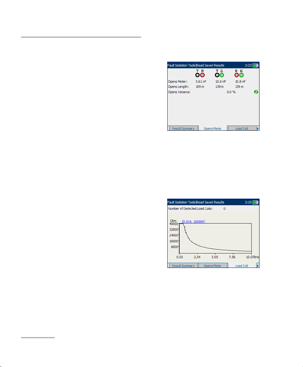
Opens Meter
Opens Meter is a measured value for
each lead combination. The test
measures the capacitance of the loop
and Opens Length.
³ Opens Length is calculated from
the corresponding capacitance
and displayed in either meter or
feet, depending on the unit
selection in Regional Settings. If
the corresponding capacitance is < 0.2 nF or > 10 μF, N/A is displayed.
³ Opens Variance is the percentage difference between the capacitance
on T-G and R-G. If the capacitances on T-G or R-G are < 0.2 nF or
>10μF, N/A is displayed and the opens variance is considered a fail
status.
Load Coil
The Load Coil tab displays the number
of load coils detected in the line.
³ If only 1 or 2, Probable Filter
Detected is displayed.
³ Splitter Detected is displayed if
present.
Measured values from the load coil
detection test are shown in graphical
form.
To move the screen pointer:
Press the left/right arrow keys to move the screen pointer. The pointer
value updates dynamically.
50 AXS-200/635i
Page 59
Running Inactive Pair Test and Viewing Results
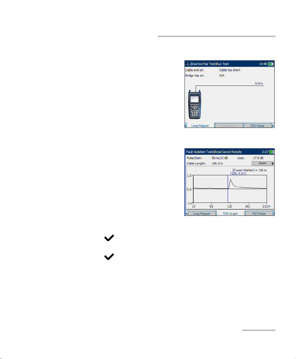
Loop Mapper
The Loop Mapper tab allows you to
view results of the Loop Mapper test in
graphical and text form.
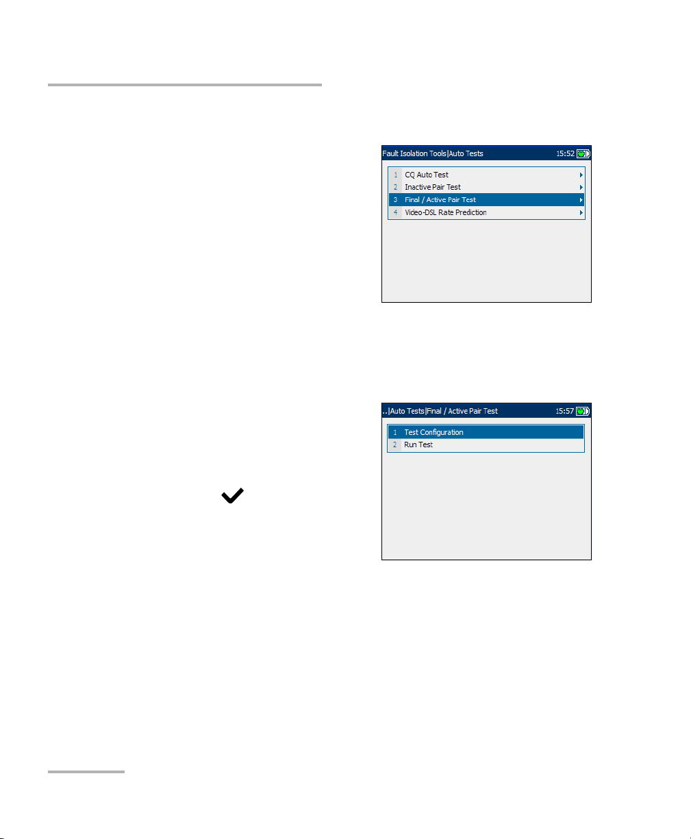
TDR Graph
The TDR Graph tab displays the
current Pulse/Gain and measured
values from the time domain
reflectometry tests. TDR first attempts
to find the length of the circuit and then
searches all ranges from shortest to
longest for significant events. Upon
completion, the test selects the nearest
major event, sets the range to match,
and aligns the cursor with the event.
Auto Tests
To make TDR adjustments via the keypad:
1. Press to change the mode button (top-right corner of the pane)
and function of the up/down arrow keys.
2. Press repeatedly to cycle between:
³ Zoom
³ CursorMarker selection
Copper, VDSL2, ADSL2+ and IP Triple-Play Test Set 51
Page 60

Auto Tests
Running Inactive Pair Test and Viewing Results
To measure the distance/duration between reflections:
1. Press to cycle the mode and change to CursorMarker.
2. Press the left/right arrow keys to position the blue cursor (indicated by
the blue color of data above cursor).
3. Press the up arrow key to select the red marker.
4. Press the left/right arrow keys to position the marker.
5. The difference between the cursor and marker is continuously
updated and is indicated with a triangle (delta symbol) above the
graph.
To zoom in/out:
1. Press to select the Zoom function. Default mode is Zoom.
2. Press the up/down arrow keys to increase/decrease Zoom function.
The graphical display zooms in or out accordingly.
52 AXS-200/635i
Page 61

Auto Tests
Running Inactive Pair Test and Viewing Results
PSD Noise
The PSD Noise tab displays the RMS
Noise value from the power spectral
density (PSD) noise tests in text and
graphical form.
The list and buttons on the tab are
described below:
³ (Zoom function List) allows you to
select the desired zoom function:
Horizontal Zoom or Vertical
Zoom. The selected function is displayed in the box.
³ Zoom In allows you to increase the level of zoom for the selected
zoom function.
³ Zoom Out allows you to reduce the level of zoom for the selected
zoom function.
To zoom in or out:
1. Press to display a list of zoom functions.
2. Press the up/down arrow keys to highlight the desired zoom function.
3. Press to select the zoom function.
4. Use the left/right arrow keys to highlight the Zoom In or Zoom Out
button as required, then press .
The graphical display zooms in or out accordingly.
5. Press repeatedly to continue zooming.
To move the screen pointer:
Press the left/right arrow keys to move the screen pointer. The pointer
value updates dynamically.
Copper, VDSL2, ADSL2+ and IP Triple-Play Test Set 53
Page 62
Auto Tests
Final/Active Pair Test
Final/Active Pair Test
The final/active pair test is an auto-test
that performs several individual
measurements in sequence. It also
automatically dials a few special
phone numbers in the phone book to
set up the line into the various specific
termination modes during the test. The
test provides a pass/fail summary as
well as detailed text/graphical results.
Configuring Final/Active Pair Test
Parameters for auto test configuration are on the Final/Active Pair Test
pane tabs.
To view the test configuration
tabs:
1. From the Final/Active Pair Test
pane use the up/down arrow keys
to highlight Test Configuration,
and press .
2. Press the F1, F2, or F3 key to view
the various tabs. To view any
available additional tabs, use the
function arrow keys on either side of the F1 and F3 keys.
54 AXS-200/635i
Page 63
Auto Tests
Configuring Final/Active Pair Test
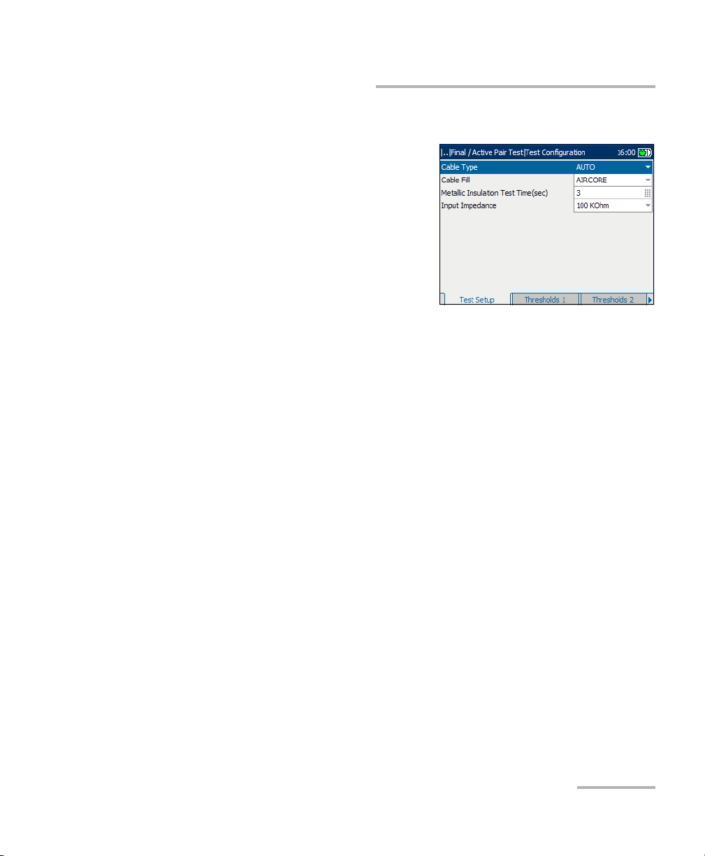
Test Setup
The Test S etup allows you to
select/adjust the setup parameters for
the Final/Active Pair Test as follows:
³ Cable Type defines the gauge of
the cable in use. If wire gauge is
measured in American Wire
Gauge (AWG) units, the available
choices are: AUTO, 19 AWG,
22 AWG, 24 AWG, or 26 AWG. For
mm gauge wire, the available choices are: AUTO, 0.32 mm, 0.40 mm,
0.50 mm, 0.60 mm, 0.65 mm, 0.80 mm, 0.90 mm, or 1.20 mm.
³ Cable Fill allows you to select the type of material the cable can be
filled with. Changing the selection to AIRCORE, JELLY, PULP, 5PR, or
2PR influences the cable capacitance per length, automatically
updating the Cap. T/R-GND field.
³ Metallic Insulation Test Time(sec) specifies the duration of the
isolation test: 1 to 15. The default is 3 seconds. A maximum of only 15
seconds is permitted for each connection so that all the measurements
will be completed before the silent switchman times out and
re-applies the battery to the line.
³ Input Impedance displays the input impedance in the loop. The
available choices are: >1 MOhm, 100 KOhm.
Copper, VDSL2, ADSL2+ and IP Triple-Play Test Set 55
Page 64

Auto Tests
Configuring Final/Active Pair Test
To set parameter values:
1. Press the up/down arrow keys to highlight the desired parameter.
2. Press to display the list or select the value.
3. Press the up/down arrow key to highlight the desired value.
OR
4. Press the left arrow key to erase the existing value, and then use the
alphanumeric keypad to enter a value. To cancel the entry, press .
5. Press to accept the value.
Thresholds 1
The Thresholds 1 tab displays the
threshold parameters for the
Final/Active Pair Test. They are part of
the CQ profile and cannot be edited on
this pane.
The parameters are described below:
³ Max. On Hook AC/DC Voltage are
the maximum AC/DC threshold
voltage values for the circuit.
³ Min. Loop Current (mA) is the minimum loop current for the circuit
in mA.
³ Max. Ground Resistance (Ohm) is the maximum ground resistance
in Ohm.
Note: The Ground Resistance function only works with central offices with the tip
connected to ground.
56 AXS-200/635i
Page 65

Auto Tests
Configuring Final/Active Pair Test
Thresholds 2
The Thresholds 2 tab displays the
threshold parameters for the Inactive
Pair Test. They are part of the CQ
profile and cannot be edited on this
pane.
³ Max. Loop Loss (dB) is the
maximum threshold loop loss
in dB.
³ Max. Power Influence (dBrnC) is
the maximum threshold power influence level on the circuit.
³ Max. Noise Metallic (dBrnC) is the maximum threshold noise energy
level on the circuit.
³ Min. Real Balance (dB) is the minimum difference between Power
Influence and Noise Metallic when the measured Power Influence is
>70dBrnC. If Power Influence is < 70 dBrnC, N/A is displayed.
³ Min. Long Balance (dB) is the minimum voice frequency threshold
longitudinal balance level.
³ Min. Metallic Insulation (MOhm) are the minimum threshold
resistance values for the circuit.
³ Max. Opens Variance (%) is the maximum capacitance balance
percentage.
Copper, VDSL2, ADSL2+ and IP Triple-Play Test Set 57
Page 66

Auto Tests
Configuring Final/Active Pair Test
Thresholds 3
The Thresholds 3 tab displays the
maximum open AC/DC voltage values
for the Inactive Pair Test. They are part
of the CQ profile and cannot be edited
on this pane.
58 AXS-200/635i
Page 67
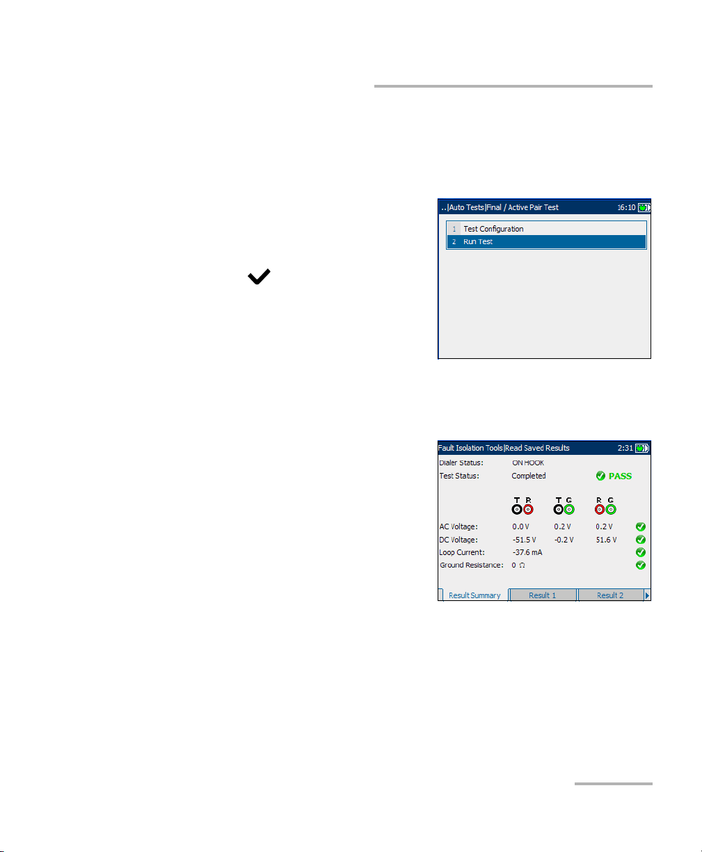
Auto Tests
Running Final/Active Pair Test and Viewing Results
Running Final/Active Pair Test and Viewing
Results
Results details are located on the Final/Active Pair Test pane tabs.
To run the tests and view results:
1. From the Final/Active Pair Test
pane use the up/down arrow keys
to highlight Run Test, and
press .
2. Press the F1, F2, or F3 key to view
the various tabs. To view any
available additional tabs, use the
function arrow keys on either side
of the F1 and F3 keys.
Result Summary
The Result Summary tab displays a
summary of the measured voltage and
current values, and pass/fail status of
the Final/Active Pair tests.
³ Dialer Status displays the current
status of the Dialer such as
ON HOOK, OFF HOOK, DIAL
TONE DETECTED, and DIALING.
³ Ground Resistance displays the
measurement result value in Ohm, comparing the customer protector
ground resistance to an active central office pair. If an incorrect leads
connection is detected, Check Leads is displayed.
Copper, VDSL2, ADSL2+ and IP Triple-Play Test Set 59
Page 68

Auto Tests
Running Final/Active Pair Tes t a n d V i ew i n g R e su l ts
Result 1
The Result 1 tab allows you to view the
results of the measured values and
pass/fail status for the Final/Active Pair
tests.
Result 2
The Result 2 tab displays more results
from the Final/Active Pair tests.
³ Met. Insulation displays the
metallic insulation values for the
circuit, ranging from 0 to
999 MOhm.
³ Opens Meter measures the
capacitance of the loop in nF, for
each lead combination.
³ Opens Length displays the corresponding capacitance in either meter
or feet, depending on the unit selection in Regional Settings. If the
corresponding capacitance is < 0.2 nF or > 10 μF, N/A is displayed.
³ Opens Variance is the percentage difference between the capacitance
on T-G and R-G.
³ Load Coil displays In Progress while running and the number of load
coils detected when the test is completed. If the number is 1 or 2,
Probable Filter Detected is displayed. Splitter Detected is displayed if
present.
Press the Details button to switch to the Load Coil tab.
60 AXS-200/635i
Page 69

Auto Tests
Running Final/Active Pair Test and Viewing Results
³ Open AC/DC Volts displays the measured values on tip, ring, and
ground, and the pass/fail status of each Final/Active Pair test.
Load Coil
The Load Coil tab displays the number
of load coils detected in the line.
³ If only 1 or 2, Probable Filter
Detected is displayed.
³ Splitter Detected is displayed if
present.
Measured values from the load coil
detection test are shown in graphical
form.
To move the screen pointer:
Press the left/right arrow keys to move the screen pointer. The pointer
value updates dynamically.
Copper, VDSL2, ADSL2+ and IP Triple-Play Test Set 61
Page 70

Auto Tests
Video-DSL Rate Prediction
Video-DSL Rate Prediction
The video-DSL rate prediction test
provides an innovative way to
understand the otherwise complicated
output of electrical and attenuation
measurements, and noise tests as they
relate to the capacity to transport IPTV
video over ADSL2+ circuits. This test
performs a series of loop-quality
measurements before predicting the
ADSL2+ data rate and Video-DSL rate.
Based on current loop conditions and user-defined technology, the
video-DSL rate prediction test shows you how many streams of standard
broadcast (SB) and high definition (HD) IPTV video streams the tested
circuit could reliably carry.
Configuring Video-DSL Rate Prediction
Parameters for auto test configuration are on the Video-DSL Rate
Prediction pane tabs.
To view the test configuration
tabs:
1. From the Video-DSL Rate
Prediction pane use the up/down
arrow keys to highlight Tes t
Configuration, and press .
2. Press the F1, F2, or F3 key to view
the various tabs. To view any
available additional tabs, use the
function arrow keys on either side of the F1 and F3 keys.
62 AXS-200/635i
Page 71

Auto Tests
Configuring Video-DSL Rate Prediction
Configuration
The Configuration tab allows you to
define the desired number of streams
and allocated bit rate per stream
before running the test.
Each parameter is described below:
³ No Of Streams is the number of
High Def. (definition) streams,
ranging from 0 to 4 and Std.
(standard) Def. streams ranging
from 0 to 10.
³ Stream Rate (Mbps) is the High Def. (HD) and Std. Def. (SD) stream
rate before running the test, ranging from 0 to 24 Mbps. Default values
are 8 Mbps for HD and 1 Mbps for SD.
³ Non-Video Data Rate (Mbps) is a data rate of non-video data typically
used by high-speed internet and VoIP services. Rates range from
0 to 24 Mbps. Default value is 1 Mbps.
³ Annex defines the modes of available ADSL Annexes from the
ITU standards.
³ A is ADSL service functioning over POTS.
³ B activates the ADSL functionality over ISDN.
³ L Mask 1 assumes an increase in ADSL2 range/distance.
³ L Mask 2 also extends the signal reach but can show an
improvement in the upstream data rate.
³ M allows increased upload speeds from 1 Mbps to 3.5 Mbps.
Available only for ADSL2 and ADSL2+.
Copper, VDSL2, ADSL2+ and IP Triple-Play Test Set 63
Page 72

Auto Tests
Configuring Video-DSL Rate Prediction
³ Technology lists the following values: ADSL2+, ADSL2, or ADSL. If
Annex L is previously selected, ADSL2 is automatically set. If Annex M,
ADSL is not available.
³ Targ et SN R is the desired signal-to-noise ratio ranging from 0 to 31 dB.
Default value is 6 dB.
To set parameter values:
1. Press the up/down or left/right arrow keys to highlight the desired
parameter.
2. Press to display the list or select the value.
3. Press the up/down arrow keys to highlight the desired value.
OR
4. Press the left arrow key to erase the existing value, and then use the
alphanumeric keypad to enter a value. To cancel the entry, press .
5. Press to accept the value.
64 AXS-200/635i
Page 73

Auto Tests
Configuring Video-DSL Rate Prediction
Thresholds
The Thresholds tab allows you to set threshold values for the auto tests.
Each parameter is described below:
³ Max AC Voltage (V) defines the
maximum AC voltage, ranging
from 1 to 20. Default value is 6.
³ Max DC Voltage (V) defines the
maximum DC voltage ranging from
1 to 20. Default value is 9.
³ Min Resistance (MOhm) defines
the minimum resistance ranging from 0.5 to 100. Default value is 3.6.
³ Max Cap. Balance (%) defines the percentage maximum capacitance
balance ranging from 0 to 20. Default value is 6.
³ Min Long Balance (dB) defines the minimum longitudinal balance
level ranging from 50 to 70. Default value is 59.
To set a threshold value:
1. Press the up/down arrow keys to highlight the desired parameter.
2. Press to select the value.
3. Press the left arrow key to erase the existing value, and then use the
alphanumeric keypad to enter a value. To cancel the entry, press .
4. Press to accept the value.
Copper, VDSL2, ADSL2+ and IP Triple-Play Test Set 65
Page 74
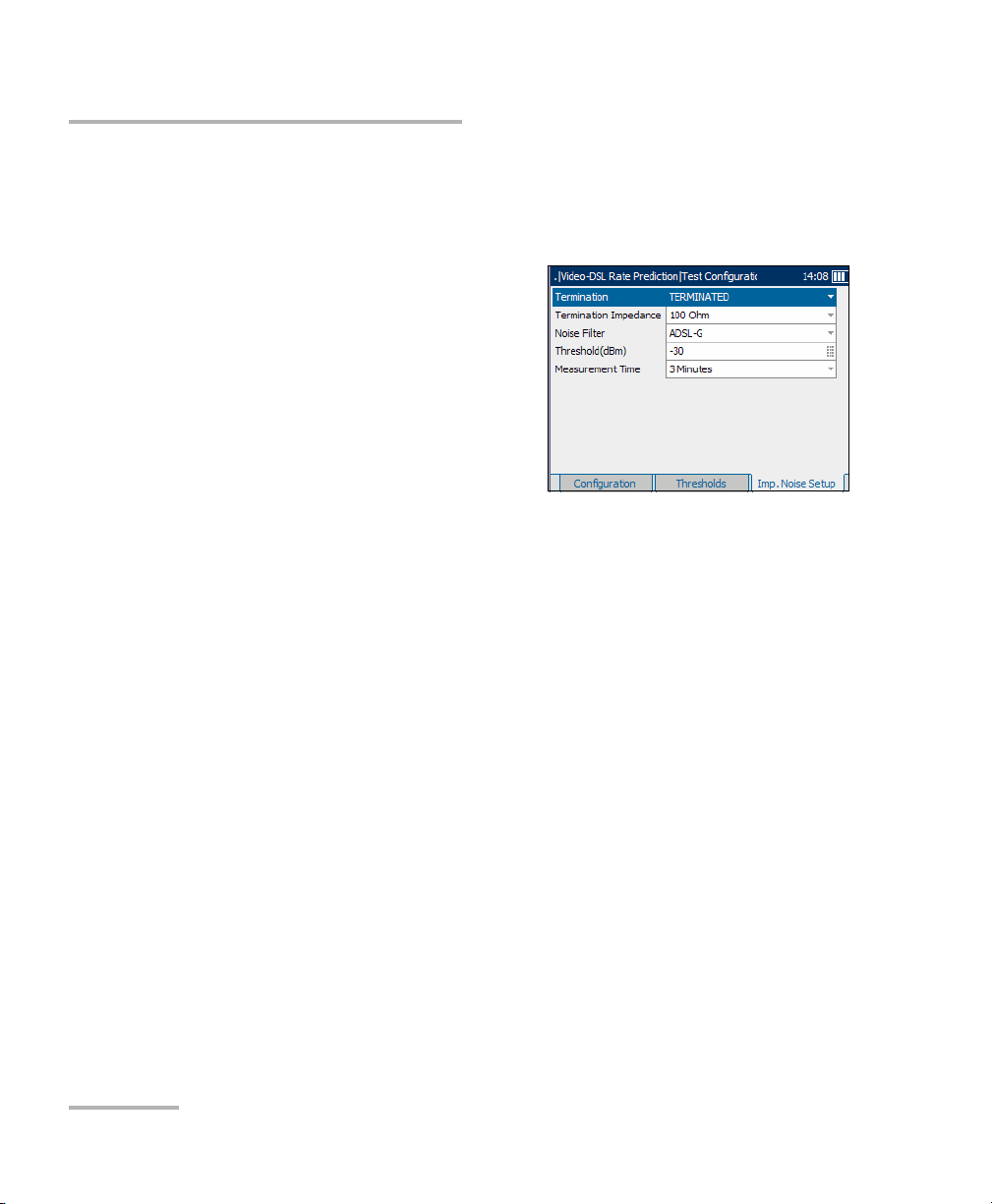
Auto Tests
Configuring Video-DSL Rate Prediction
Impulse Noise Setup
The Imp. Noise Setup tab allows you to configure parameters to measure
impulse noise on the circuit under test.
Each parameter on the pane is
described below.
³ Ter mi na ti on defines if the unit
uses normal test impedance
termination or high bridging
impedance when the cable is
active or terminated by other
external equipment. For normal
test termination select
TERMINATED, otherwise select BRIDGING.
³ Termination Impedance defines the impedance of the dummy load
connected to the line. Select one of the following: 100 or 135 Ohm.
³ Noise Filter defines the level of wideband noise filtering. The available
choices are: NONE, 50 kbit, ISDN-E, HDSL-F, ADSL-G, ADSL, ADSL2+,
VDSL, VDSL2-8, VDSL2-12, VDSL2-17, or VDSL2-30.
Note: VDSL2-x filters are only available if VDSL2WB is enabled in the software
options.
³ Threshold(dBm) is the maximum impulse noise level. Specify a value
between -50 and 0 (-40 and 0 if any filter applied). Default value is -30.
³ Measurement Time defines the duration of the Impulse Noise test. The
available choices are: 1, 3, 5, 10, 15, or 60 Minutes, or 24 Hours.
66 AXS-200/635i
Page 75
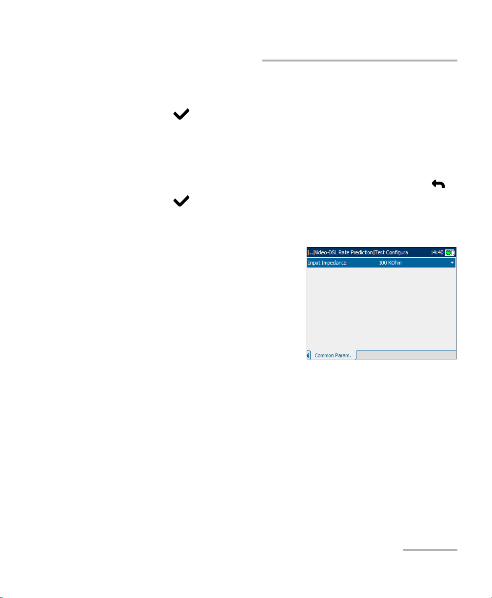
Auto Tests
Configuring Video-DSL Rate Prediction
To set parameter values:
1. Press the up/down arrow keys to highlight the desired parameter.
2. Press to display the list or select the value.
3. Press the up/down arrow keys to highlight the desired value.
OR
4. Press the left arrow key to erase the existing value, and then use the
alphanumeric keypad to enter a value. To cancel the entry, press .
5. Press to accept the value.
Common Parameters
The Common Param. tab allows you to
set up the Input Impedance in the
loop. The available choices are:
>1 MOhm, 100 KOhm.
Copper, VDSL2, ADSL2+ and IP Triple-Play Test Set 67
Page 76

Auto Tests
Running Video-DSL Rate Prediction Tests and Viewing Results
Running Video-DSL Rate Prediction Tests and
Viewing Results
Details of the video-data rate prediction results are located on the
Video-DSL Rate Prediction pane tabs.
To run the tests and view results:
1. From the Video-DSL Rate
Prediction pane use the up/down
arrow keys to highlight Run Test,
and press .
2. Once the tests are completed,
highlight the Details button from
the Test Summary pane and
press to view the results.
3. Press the F1, F2, or F3 key to view the various tabs. To view any
available additional tabs, use the function arrow keys on either side of
the F1 and F3 keys.
Test Summary
The Test Summary tab allows you to view the pass/fail status and Details
of all tests configured for auto testing.
The available test results are the
following:
³ Multi-meter Tests or digital
multi-meter tests detect AC/DC
voltages, and measure frequency,
resistance and capacitance for the
copper wire connection.
³ Load Coils Detected is the
number load coals detected in
the line.
68 AXS-200/635i
Page 77

Auto Tests
Running Video-DSL Rate Prediction Tests and Viewing Results
³ WB Long. Balance measures the wide band longitudinal balance of
the broadband service.
³ WB PSD Noise measures the wide band power spectral density noise
on the line.
³ WB Attenuation measures the cable length value from wide band
attenuation tests.
³ WB Impulse Noise measures values from the wideband impulse
noise tests.
³ Data Rate Test predicts the maximum bit rate achievable on the
local loop based on Annex, Technology, and Tar ge t SNR selected.
³ HD Streams is the number of high definition streams carried on the
local loop. Again, the pass indicator is displayed only if the analyzed
number of HD streams matches the number set on the Configuration
tab. Otherwise the status is fail.
³ SD Streams is the number of standard definition streams carried on
the local loop. Here, the pass indicator is displayed only if the analyzed
number of SD streams matches the number set on the Configuration
tab. Otherwise the status is fail.
³ Predicted Rate displays the downstream and upstream predicted
data rates.
³ The Details button navigates you to the applicable results tab which
provides more information about a particular test.
To view more information about each available test result:
1. Press the up/down arrows to highlight the Details button alongside the
desired test result.
2. Press to select the desired Details button.
3. To return to the Test Summary pane, press .
Copper, VDSL2, ADSL2+ and IP Triple-Play Test Set 69
Page 78
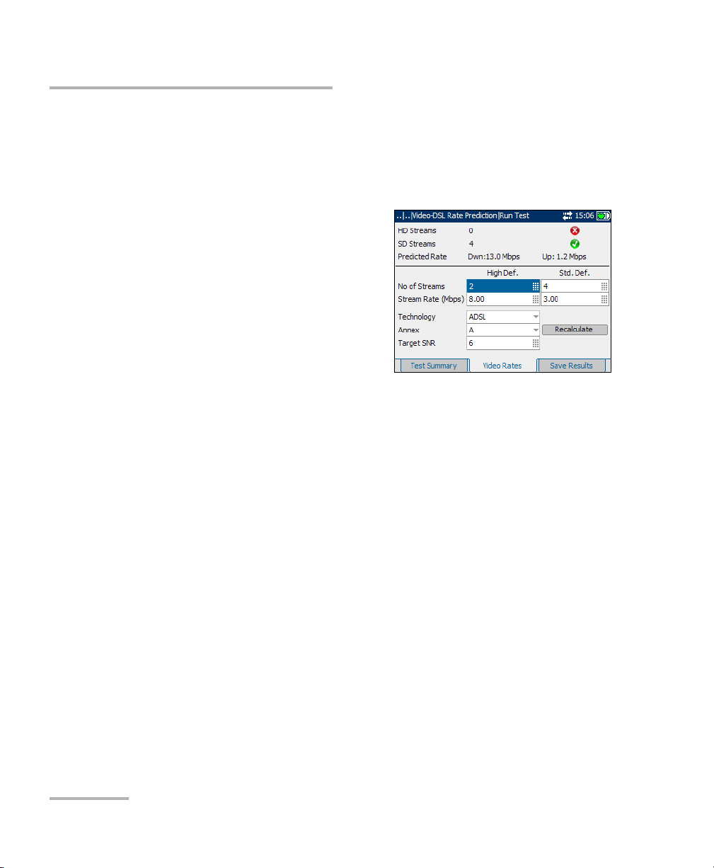
Auto Tests
Running Video-DSL Rate Prediction Tests and Viewing Results
Video Rates
The Video Rates tab allows you to view the pass/fail status, details and
predicted data rate of the high and standard definition streams carried on
the local loop.
Configurable parameters include:
³ No of Streams is the number of
High Def. (definition) streams,
ranging from 0 to 4 and Std.
(standard) Def. streams ranging
from 0 to 10.
³ Stream Rate (Mbps) is the High
Def. (HD) and Std. Def. (SD)
stream rate before running the test,
ranging from 0 to 24 Mbps. Default values are 8 Mbps for HD and
1Mbps for SD.
³ Technology lists the following values: ADSL2+, ADSL2, or ADSL. If
Annex L is previously selected, ADSL2 is automatically set. If Annex M,
ADSL is not available.
³ Annex defines the modes of available ADSL Annexes from the
ITU standards.
³ A is ADSL service functioning over POTS.
³ B activates the ADSL functionality over ISDN.
³ L Mask 1 assumes an increase in ADSL2 range/distance.
³ L Mask 2 also extends the signal reach but can show an
improvement in the upstream data rate.
³ M allows increased upload speeds from 1 Mbps to 3.5 Mbps.
Available only for ADSL2 and ADSL2+.
70 AXS-200/635i
Page 79
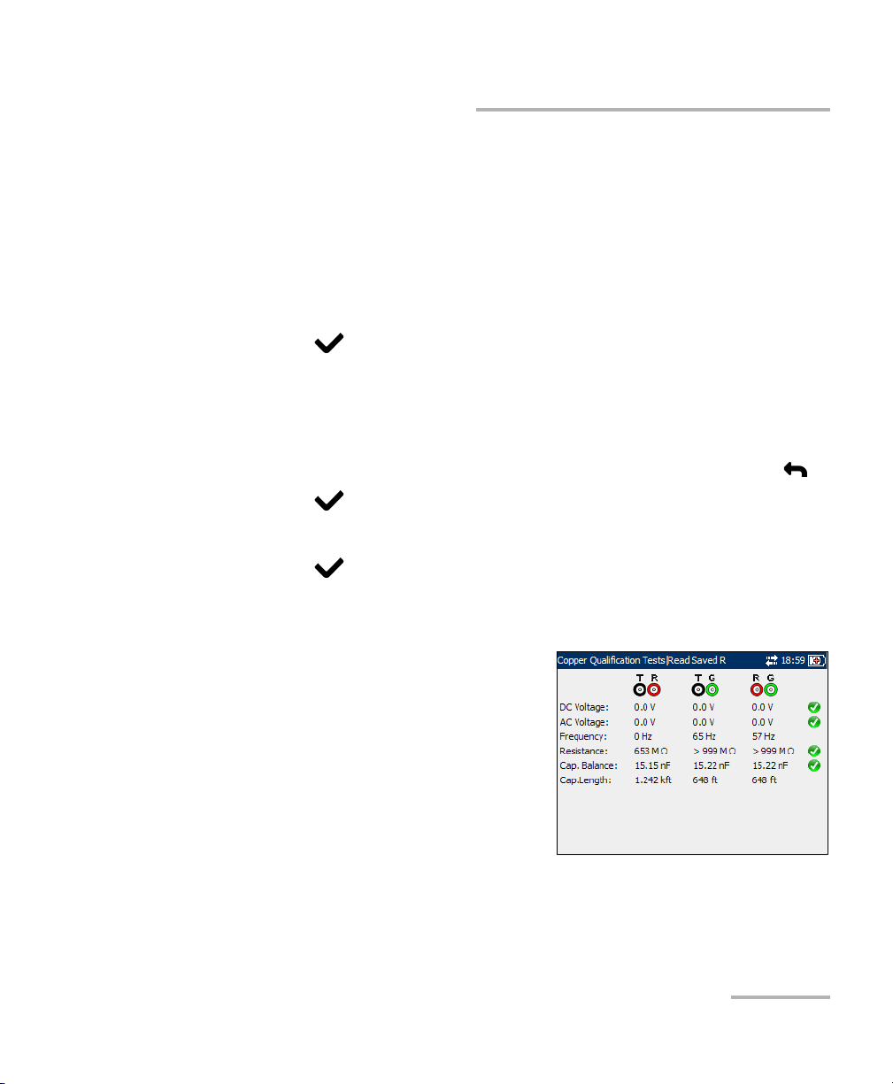
Auto Tests
Running Video-DSL Rate Prediction Tests and Viewing Results
³ Targ et SN R is the desired signal-to-noise ratio ranging from 0 to 31 dB.
Default value is 6 dB.
³ Recalculate button allows you to change the setup and re-evaluate the
rates.
To re-set parameters to view different results:
1. Press the up/down or left/right arrow keys to highlight the desired
parameter.
2. Press to display the list or select the value.
3. Press the up/down arrow keys to highlight the desired value.
OR
4. Press the left arrow key to erase the existing value, and then use the
alphanumeric keypad to enter a value. To cancel the entry, press .
5. Press to accept the value.
6. Press the up/down arrow keys to highlight the Recalculate button.
7. Press to recalculate rates for the new setup.
Multi-meter Tests
The multi-meter tests results pane
displays the measured values on tip,
ring, and ground, and the pass/fail
status of each digital multi-meter test.
Copper, VDSL2, ADSL2+ and IP Triple-Play Test Set 71
Page 80

Auto Tests
Running Video-DSL Rate Prediction Tests and Viewing Results
WB Longitudinal Balance
The WB Long. Balance pane displays
the results of the wideband
longitudinal balance test in graphical
form.
The buttons on the tab are described
below:
³ (Zoom function List) allows you to
select the desired zoom function:
Horizontal Zoom or Vertical
Zoom. The selected function is displayed in the box.
³ Zoom In allows you to increase the level of zoom for the selected
zoom function.
³ Zoom Out allows you to reduce the level of zoom for the selected
zoom function.
To zoom in/out:
1. Press to display a list of zoom functions.
2. Press the up/down arrow key to highlight the desired zoom function.
3. Press to select the zoom function.
4. Use the left/right arrow key to highlight the Zoom In or Zoom Out
button as required, then press .
5. The graphical display zooms in or out accordingly. Press
repeatedly to continue zooming.
To move the screen pointer:
Press the left/right arrow key to move the screen pointer. The pointer value
updates dynamically.
72 AXS-200/635i
Page 81

Auto Tests
Running Video-DSL Rate Prediction Tests and Viewing Results
WB PSD Noise
The WB PSD Noise pane displays the
RMS Noise value from the power
spectral density (PSD) noise tests in
text and graphical form. RMS noise
voltage measures the signal-to-noise
ratio of the circuit.
The list and buttons on the tab are
described below:
³ (Zoom function List) allows you to
select the desired zoom function: Horizontal Zoom or Vertical Zoom.
The selected function is displayed in the box.
³ Zoom In allows you to increase the level of zoom for the selected
zoom function.
³ Zoom Out allows you to reduce the level of zoom for the selected
zoom function.
To zoom in or out:
1. Press to display a list of zoom functions.
2. Press the up/down arrow keys to highlight the desired zoom function.
3. Press to select the zoom function.
4. Use the left/right arrow keys to highlight the Zoom In or Zoom Out
button as required, then press .
The graphical display zooms in or out accordingly.
5. Press repeatedly to continue zooming.
To move the screen pointer:
Press the left/right arrow keys to move the screen pointer. The pointer
value updates dynamically.
Copper, VDSL2, ADSL2+ and IP Triple-Play Test Set 73
Page 82

Auto Tests
Running Video-DSL Rate Prediction Tests and Viewing Results
WB Attenuation
The WB Attenuation pane displays the
wideband attenuation test results in
graphical form.
The list and buttons on the tab are
described below:
³ (Zoom function List) allows you to
select the desired zoom function:
Horizontal Zoom or Vertical
Zoom. The selected function is
displayed in the box.
³ Zoom In allows you to increase the level of zoom for the selected
zoom function.
³ Zoom Out allows you to reduce the level of zoom for the selected
zoom function.
To zoom in/out:
1. Press to display a list of zoom functions.
2. Press the up/down arrow key to highlight the desired zoom function.
3. Press to select the zoom function.
4. Use the left/right arrow key to highlight the Zoom In or Zoom Out
button as required, then press .
5. The graphical display zooms in or out accordingly. Press
repeatedly to continue zooming.
To move the screen pointer:
Press the left/right arrow key to move the screen pointer. The pointer value
updates dynamically.
74 AXS-200/635i
Page 83

Running Video-DSL Rate Prediction Tests and Viewing Results
WB Impulse Noise
The WB Impulse Noise pane displays
the measured values from the
wideband impulse noise tests.
DSL Rate Tests
The DSL Rate tab allows you to view
the down/up stream Predicted Rate
based on measurements of PSD noise
and attenuation.
Configurable parameters include:
³ Annex lists the modes of available
ADSL Annexes from the
ITU standards.
Auto Tests
³ A is ADSL service functioning over POTS.
³ B activates the ADSL functionality over ISDN.
³ L Mask 1 assumes an increase in ADSL2 range/distance.
³ L Mask 2 also extends the signal reach but can show an
improvement in the upstream data rate.
³ M allows increased upload speeds from 1 Mbps to 3.5 Mbps.
Available only for ADSL2 and ADSL2+.
³ Targ et SN R is the desired signal-to-noise ratio ranging from 0 to 31 dB.
Default value is 6 dB.
Copper, VDSL2, ADSL2+ and IP Triple-Play Test Set 75
Page 84

Auto Tests
Running Video-DSL Rate Prediction Tests and Viewing Results
³ Technology lists the following values: ADSL2+, ADSL2, or ADSL. If
Annex L is previously selected, ADSL2 is automatically set. If Annex M,
ADSL is not available.
³ Recalculate button allows you to change the setup and re-evaluate the
rates.
To re-set parameters to view different results:
1. Press the up/down or left/right arrow keys to highlight the desired
parameter.
2. Press to display the list or select the value.
3. Press the up/down arrow keys to highlight the desired value.
OR
4. Press the left arrow key to erase the existing value, and then use the
alphanumeric keypad to enter a value. To cancel the entry, press .
5. Press to accept the value.
6. Press the up/down arrow keys to highlight the Recalculate button.
7. Press to recalculate rates for the new setup.
76 AXS-200/635i
Page 85

Auto Tests
Running Video-DSL Rate Prediction Tests and Viewing Results
Signal-to-Noise Ratio
The SNR tab displays the
signal-to-noise ratio per tone in
graphical form.
The list and buttons on the tab are
described below:
³ (Zoom function List) allows you to
select the desired zoom function:
Horizontal Zoom or Vertical
Zoom. The selected function is
displayed in the box.
³ Zoom In allows you to increase the level of zoom for the selected
zoom function.
³ Zoom Out allows you to reduce the level of zoom for the selected
zoom function.
To zoom in or out:
1. Press to display a list of zoom functions.
2. Press the up/down arrow keys to highlight the desired zoom function.
3. Press to select the zoom function.
4. Use the left/right arrow keys to highlight the Zoom In or Zoom Out
button as required, then press .
The graphical display zooms in or out accordingly.
5. Press repeatedly to continue zooming.
To move the screen pointer:
Press the left/right arrow keys to move the screen pointer. The pointer
value updates dynamically.
Copper, VDSL2, ADSL2+ and IP Triple-Play Test Set 77
Page 86

Auto Tests
Running Video-DSL Rate Prediction Tests and Viewing Results
Bits per Bin
The Bits per Bin tab displays in
graphical form the number of bits that
can be transmitted on a particular bin
representing a certain tone.
³ Zoom In allows you to increase
the level of zoom for the selected
zoom function.
³ Zoom Out allows you to reduce
the level of zoom for the selected
zoom function.
To zoom in or out:
1. Press the up or down arrow key to highlight the desired zoom function.
2. Press to select the zoom function.
3. Use the left or right arrow key to highlight the Zoom In or Zoom Out
button as required, then press .
The graphical display zooms in or out accordingly.
4. Press repeatedly to continue zooming.
To move the screen pointer:
Press the left/right arrow keys to move the screen pointer. The pointer
value updates dynamically.
78 AXS-200/635i
Page 87

4 POTS Auto Test
The purpose of the POTS Auto Test function is to detect the Loop Current
and measure the voice frequency in a copper telephone loop. This test
allows you to compare measured results against stored threshold values to
provide pass or fail status results of the POTS circuit type.
To access POTS Auto Test:
1. From the Home pane use the up/down arrow keys to highlight Fault
Isolation Tools and press .
2. Highlight POTS Auto Test and press to start the test.
To view POTS Auto Test tabs:
From the POTS Auto Test pane use the F1, F2, or F3 key to view the various
tabs.
Thresholds
The Thresholds tab allows you to set threshold values for the
POTS auto test.
Each parameter is described below:
³ Min Loop Current (mA) is a value
ranging from 10 to 100. Default
is 23.
³ Max Loss (dB) is a value ranging
from 0 to 50. Default is 8.
³ Max VF Power Influence is a value
ranging from -90 to 10 dBm with a
default of -10, if the ITU Standard is used. If ANSI Standard, the range is
from 0 to 100 dBrn with a default value of 80.
³ Max Noise Metallic is a value ranging from -90 to 10 dBm with a
default of -70, if the ITU Standard is used. If ANSI Standard, the range is
from 0 to 100 dBrn with a default value of 20.
³ Min Long Balance (dB) is a value ranging from 0 to 100. Default is 60.
Copper, VDSL2, ADSL2+ and IP Triple-Play Test Set 79
Page 88
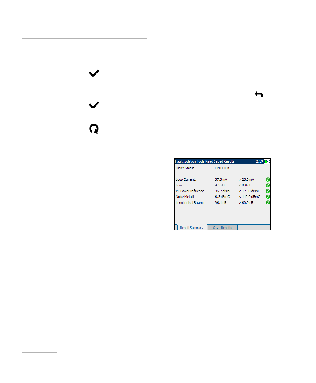
POTS Auto Test
To set a threshold value and start/stop the test:
1. Press the up/down arrow keys to highlight the desired parameter.
2. Press to select the value.
3. Press the left arrow key to erase the existing value, and then use the
4. Press to accept the value.
5. Select other parameters as required.
6. Press to start/stop the test.
Result
The Result tab allows you to view
detailed results of the Loop Current,
voice frequency measurement values
and Pass/Fail status of the POTS Auto
Tes t.
alphanumeric keypad to enter a value. To cancel the entry, press .
80 AXS-200/635i
Page 89

5 Multi-meter Tests
The purpose of the multi-meter tests function is to detect AC/DC voltages
and currents, and measure resistance and capacitance in a loop. These
tests allow you to make basic electrical safety checks (AC volts), check
from crossed or coupled battery voltages, assess basic loop continuity and
quality with resistance measurements, and measure total electrical length
with capacitance.
To access Multi-meter tests:
1. From the Home pane, highlight Multi-meter and press to start the
test.
OR
2. From the Home pane use the up/down arrow keys to highlight Fault
Isolation Tools and press .
3. Highlight Multi-meter Tests and press to list the available tests.
The Multi-meter Tests menu includes
the following tests:
³ Multi-meter
³ In-service pair, rectified loop, and
water detection
³ Resistive balance
Multi-meter
The Multi-meter function allows you to perform the following tests:
³ Voltage
³ Ground Resistance
³ Resistance (also known as shorts meter)
³ Metallic
³ Capacitance (also known as opens meter)
³ Current
Copper, VDSL2, ADSL2+ and IP Triple-Play Test Set 81
Page 90

Multi-meter Tests
Multi-meter
³ Noise Metallic
³ Longitudinal Balance
³ Dialer
To view Multi-meter test tabs:
From the Multi-meter pane use the F1, F2, or F3 key to view the various
tabs. To view any available additional tabs, use the function arrow keys on
either side of the F1 and F3 keys.
Voltage
The Vol tage tab shows measured volts
for each lead combination and allows
you to measure AC/DC voltages and
Frequency on tip, ring, and ground
(A/B/Earth).
Each parameter is described below.
³ Input Impedance displays the
input impedance in the loop. The
available choices are: >1 MOhm,
100 KOhm.
³ Connection defines the type of cable connection to be tested, as
specified in Regional Settings.
To start/stop the test:
1. Press the up/down arrow keys to highlight the desired test parameter.
2. Press to open the list.
3. Press the up/down arrow keys to highlight the desired value, then press
to select it.
4. Select other parameters as required.
5. Press to start/stop the test.
Test results are displayed on the screen as they are completed.
82 AXS-200/635i
Page 91

Ground Resistance
³ The Ground Resistance
measurement compares the
customer protector ground
resistance to an active central
office pair. If an incorrect leads
connection is detected during the
measurement, Please check wire
connections is displayed.
Note: The Ground Resistance function only
works with central offices with the tip connected to ground.
Resistance
The Resistance tab allows you to
measure the current resistance value
and cable length for the cable
connection.
Multi-meter Tests
Multi-meter
Note: If the ANSI standard is used, the tab
name Resistance changes to
Shorts Meter.
Each parameter is described below.
³ Cable Type defines the gauge of
the cable in use. Select the wire
gauge measured as Auto, in AWG
units, or in mm.
Copper, VDSL2, ADSL2+ and IP Triple-Play Test Set 83
Page 92

Multi-meter Tests
Multi-meter
³ Connection defines the type of cable connection to be tested, as
specified in Regional Settings.
³ Tem pe ra tu re (F/C) is the temperature of the cable.
To start/stop the test:
1. Press the up/down arrow keys to highlight the desired test parameter.
2. Press to open the list or specify a value.
3. Press the up/down arrow keys to highlight the desired value.
OR
4. Press the left/right arrow keys to erase the existing value, and then use
the alphanumeric keypad to enter a value. To cancel the entry, press
5. Press to accept the value.
6. Select other parameters as required.
7. Press to start/stop the test.
.
Test results are displayed on the screen as they are completed.
84 AXS-200/635i
Page 93
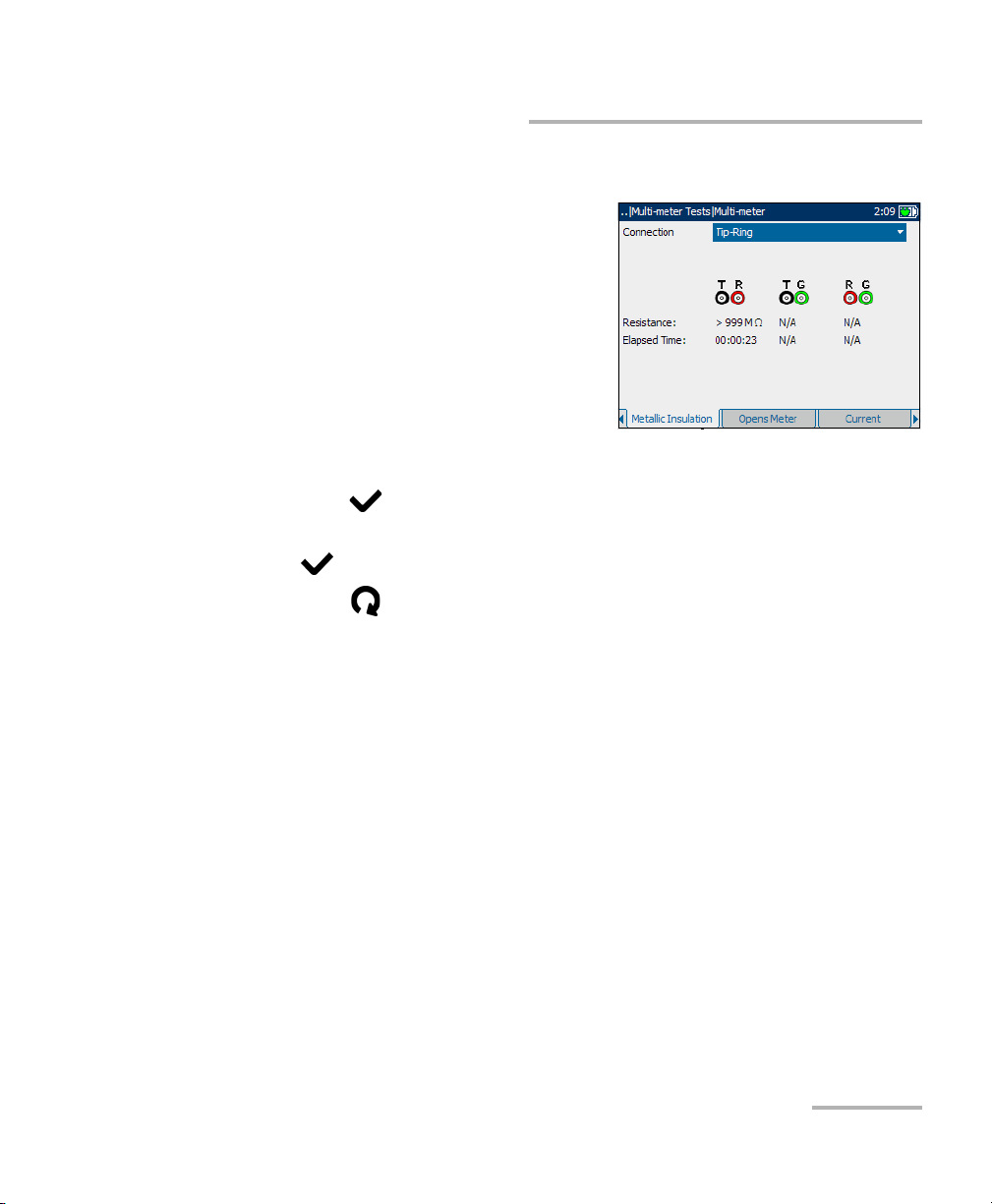
Multi-meter Tests
Multi-meter
Metallic Insulation
The Metallic Insulation tab allows you
to run a resistance test over a period of
time to look for high-resistive faults.
This method may also reveal poor
wire.
Connection defines the type of cable
connection to be tested, as specified in
Regional Settings.
To start/stop the test:
1. Press the up/down arrow keys to highlight the desired test parameter.
2. Press to open the list.
3. Press the up/down arrow keys to highlight the desired value, then press
to select it.
4. Press to start/stop the test.
Test results are displayed on the screen as they are completed.
Copper, VDSL2, ADSL2+ and IP Triple-Play Test Set 85
Page 94

Multi-meter Tests
Multi-meter
Capacitance
The Capacitance tab allows you to
measure the capacitance of the loop
and capacitance length.
Note: If the ANSI standard is used, the tab
name Capacitance changes to
Opens Meter.
³ Cable Fill allows you to select the
type of material the cable can be
filled with.
³ Connection defines the type of
connection to be tested.
³ Cap balance threshold (nF) is the capacitance balance threshold
ranging from 0.1 to 20 nF. If the measured capacitive balance in nF is
greater than this threshold, FAIL is displayed. Otherwise, PA SS is
displayed.
³ Cap balance threshold (%) is the capacitance balance threshold
ranging from 50 to 100 %. If the measured capacitance balance in
percentage is greater than this threshold, PASS is displayed. Otherwise,
FAI L is displayed.
³ Low cap value (nF) defines which of the above thresholds will be
used to determine pass or fail. The range is 0.1 to 500 nF. If the loop
capacitance is less than the Low cap value, the threshold in
Cap balance threshold (nF) will be used. Otherwise, the threshold in
Cap balance threshold (%) is used.
86 AXS-200/635i
Page 95
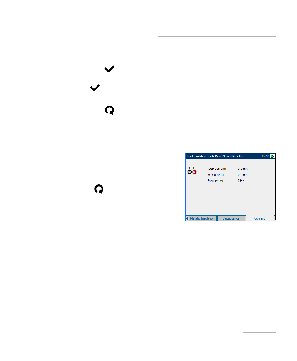
Multi-meter Tests
Multi-meter
To start/stop the test:
1. Press the up/down arrow keys to highlight the desired test parameter.
2. Press to open the list.
3. Press the up/down arrow keys to highlight the desired value, then press
to select it.
4. Select other parameters as required.
5. Press to start/stop the test.
Test results are displayed on the screen as they are completed.
Current
The Current tab allows you to
measure the AC/Loop currents and
frequency in the loop.
To start/stop the test:
Press to start/stop the test.
Test results are displayed on the screen
as they are completed.
Copper, VDSL2, ADSL2+ and IP Triple-Play Test Set 87
Page 96

Multi-meter Tests
Multi-meter
Noise Metallic
The Noise Metallic test allows you to
measure the amount of unwanted or
disturbing energy introduced into a
loop from man-made and natural
sources.
Each parameter is described below.
³ Ter mi na ti on is either BRIDGING if
the unit uses high bridging
impedance when the cable is
active or terminated by other external equipment, or TERMINATED if
the unit uses normal test impedance termination.
³ Noise Filter is either PSOPHOMETRIC for ITU standard or C-MESSAGE
for ANSI standard.
To start/stop the test:
1. Press the up/down arrow keys to highlight the desired test parameter.
2. Press to open the list.
3. Press the up/down arrow keys to highlight the desired value, then press
to select it.
4. Select other parameters as required.
5. Press to start/stop the test.
Test results are displayed on the screen as they are completed.
88 AXS-200/635i
Page 97

Multi-meter Tests
Longitudinal Balance
The Long. Balance test allows you to
check that the longitudinal balance
ratio for the twisted pair complies with
applicable standards so as to reduce
the effects of common-mode voltage
to ground. The better the longitudinal
balance of the cable pair, the higher
the dB reading.
To start/stop the test:
Press to start/stop the test.
Test results are displayed on the screen as they are completed.
Multi-meter
Copper, VDSL2, ADSL2+ and IP Triple-Play Test Set 89
Page 98

Multi-meter Tests
In Service Pair Detection Test
In Service Pair Detection Test
At the start of the In Service Pair Detection test, the unit will check for the
presence of dangerous voltage and an active circuit. If dangerous voltage is
detected, a dialog box will be displayed to inform you and the test will stop.
If an active circuit is detected, a dialog box will be displayed to ask you
whether or not to proceed with the test.
In Service
The In Service Pair Detection Test
uses the black and green (ground)
leads to quickly check if wire pairs are
in service or available for usage. This
test checks for the following:
³ dangerous voltages
³ high voltages
³ POTS battery (>30 V)
³ digital service signals
³ a bad ground connection
Note: Test beeps or warns at the end of a test ‘cycle’ and to indicate you can
move to another pair. The unit beeps faster, displaying a dialogue box,
when something (battery, earth or digital service) is detected.
90 AXS-200/635i
Page 99

Multi-meter Tests
Rectified Loop (Corrosion) Detection Test
Rectified Loop (Corrosion) Detection Test
The Rect. L Detection tab displays a
rectified loop state which often
indicates the presence of corrosion on
a circuit. Rectified loops can disrupt
balance and make the circuit
unsuitable for Broadband and other
digital services.
Water Detection Test
The Water Detection Test detects the
presence of water in the circuit. Use
the TDR to locate.
Copper, VDSL2, ADSL2+ and IP Triple-Play Test Set 91
Page 100

Multi-meter Tests
Resistive Balance
Resistive Balance
At the start of the Resistive Balance test, the unit will check for the
presence of dangerous voltage and an active circuit. If dangerous voltage is
detected, a dialog box will be displayed to inform you and the test will stop.
If an active circuit is detected, a dialog box will be displayed to ask you
whether or not to proceed with the test.
Test Setup
The Test Setup tab allows you to
configure parameters for the resistive
balance test.
Each parameter is described below:
³ Res. Bal. Thr. (ohm) is the
resistive balance threshold ranging
from 0.1 to 20 ohm. If the
measured resistive balance in
ohms is greater than this threshold,
the fail icon is displayed. Otherwise, the pass icon is displayed.
³ Res. Bal. Thr. (%) is the resistive balance threshold ranging from 50 to
100 %. If the measured resistive balance in percentage is greater than
this threshold, the pass icon is displayed. Otherwise, the fail icon is
displayed.
³ Low Resistance Value defines which of the above thresholds will be
used to determine pass or fail. The range is 0.1 to 999.9 ohm. If the loop
resistance is less than the Low Resistance Value, the threshold in
Res. Bal. Thr. (ohm) will be used. Otherwise, the threshold in
Res. Bal. Thr. (%) is used.
92 AXS-200/635i
 Loading...