

Page 1
RTU-310/310G
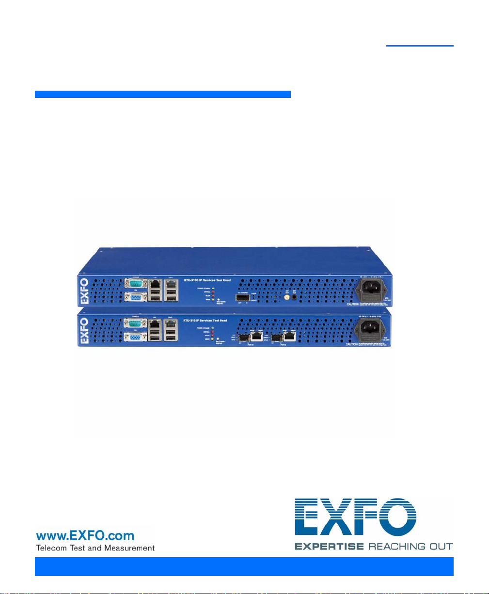
RTU-310/310G IP Services Test Head
User Guide
Page 2

Copyright © 2007–2012 EXFO Inc. All rights reserved. No part of this
publication may be reproduced, stored in a retrieval system or transmitted
in any form, be it electronically, mechanically, or by any other means such
as photocopying, recording or otherwise, without the prior written
permission of EXFO Inc. (EXFO).
Information provided by EXFO is believed to be accurate and reliable.
However, no responsibility is assumed by EXFO for its use nor for any
infringements of patents or other rights of third parties that may result from
its use. No license is granted by implication or otherwise under any patent
rights of EXFO.
EXFO’s Commerce And Government Entities (CAGE) code under the North
Atlantic Treaty Organization (NATO) is 0L8C3.
The information contained in this publication is subject to change without
notice.
Trademarks
EXFO’s trademarks have been identified as such. However, the presence
or absence of such identification does not affect the legal status of any
trademark.
Units of Measurement
Units of measurement in this publication conform to SI standards and
practices.
January 31, 2012
Version number: 7.0.0
ii RTU-310/310G
Page 3

Contents
Contents
Certification Information ....................................................................................................... ix
1 Introducing the RTU-310/310G ..................................................................... 1
Features ..................................................................................................................................1
Models ....................................................................................................................................3
Option ....................................................................................................................................5
Optical Transceivers (SFP) ........................................................................................................5
Optical Transceivers (XFP) .......................................................................................................6
Conventions ............................................................................................................................7
2 Safety Information ....................................................................................... 9
Laser Safety Warnings .............................................................................................................9
Installation Instruction Warnings ..........................................................................................10
3 Getting Started .......................................................................................... 13
Front Panel Description .........................................................................................................13
SHUT DOWN / RESTART Button .............................................................................................14
RTU-310/310G LEDs ..............................................................................................................15
VGA Port ...............................................................................................................................15
Console Port .........................................................................................................................15
USB Ports ..............................................................................................................................15
Installing the RTU-310/310G in a Rack ..................................................................................16
Connecting the Power ..........................................................................................................18
Turning the Unit On ..............................................................................................................21
Connecting the Test Interface Ports ......................................................................................22
Connecting the Management Interfaces ...............................................................................28
Software Management .........................................................................................................32
4 Introducing the Smart User Interface ....................................................... 37
Login ....................................................................................................................................37
Main Window .......................................................................................................................39
Global Test Status and Controls ............................................................................................44
Favorites ...............................................................................................................................48
Test Report Generation .........................................................................................................50
Typical Tab Elements .............................................................................................................54
Tab Configuration .................................................................................................................57
Keyboard Usage ....................................................................................................................61
Ethernet Test Module iii
Page 4

Contents
5 Creating and Starting a Test Case ..............................................................67
Introducing the Test Setup ....................................................................................................68
Test Case Availability .............................................................................................................72
EtherSAM (Y.1564) Test Case .................................................................................................73
Ethernet EtherSAM (Y.1564) and RFC 2544 Dual Test Set Test Cases .....................................80
Ethernet RFC 2544 Test Case .................................................................................................89
Ethernet BERT Test Case ........................................................................................................95
Ethernet Frame Analyzer Test Case ......................................................................................102
Ethernet Smart Loopback Test Case ....................................................................................109
Ethernet TCP Throughput Test Case ....................................................................................113
Fibre Channel BERT Test Case ..............................................................................................116
6 Summary Tabs ...........................................................................................121
Test Summary .....................................................................................................................121
Alarm Summary ..................................................................................................................128
Test Logger .........................................................................................................................131
7 Port Tabs ....................................................................................................133
Electrical TX ........................................................................................................................134
Electrical RX ........................................................................................................................136
Optical TX ...........................................................................................................................138
Optical RX ...........................................................................................................................140
Interface Setup (Ethernet) ...................................................................................................142
Interface Setup (Fibre Channel) ..........................................................................................146
Network ..............................................................................................................................150
Advanced Auto-Neg. TX .....................................................................................................154
Advanced Auto-Neg. RX .....................................................................................................159
8 Stream Generation Tabs ...........................................................................161
Overview .............................................................................................................................162
Stream Configuration .........................................................................................................166
PBB-TE ................................................................................................................................175
MAC ...................................................................................................................................177
MPLS ..................................................................................................................................180
IP/UDP/TCP ..........................................................................................................................182
Payload ...............................................................................................................................185
Frame Configuration (Fibre Channel) ..................................................................................186
9 Stream Analyzer Tabs ...............................................................................195
Overview .............................................................................................................................195
Stream ................................................................................................................................197
iv RTU-310/310G
Page 5

Contents
10 Traffic Analyzer Tabs ................................................................................ 199
Ethernet TX .........................................................................................................................200
Ethernet RX ........................................................................................................................203
Ethernet Statistics ...............................................................................................................206
PBB-TE ................................................................................................................................208
Higher Layers ......................................................................................................................210
Flow Control .......................................................................................................................212
Traffic Filters .......................................................................................................................215
Traffic Filter Configuration ..................................................................................................220
Traffic Filter Stats ................................................................................................................222
Capture ...............................................................................................................................224
Graph .................................................................................................................................229
FC TX ..................................................................................................................................230
FC RX ..................................................................................................................................233
FC Latency ..........................................................................................................................235
FC Statistics ........................................................................................................................237
11 WIS Tabs .................................................................................................... 239
WIS TX ................................................................................................................................239
WIS RX ................................................................................................................................243
WIS OH RX ..........................................................................................................................246
12 IPTV Tabs ................................................................................................... 249
IPTV Testing with the RTU-310 ............................................................................................250
Discovery ............................................................................................................................252
Overview .............................................................................................................................256
MDI/TR 101 290 ..................................................................................................................271
IGMP ...................................................................................................................................278
Stream Information ............................................................................................................284
13 Pattern Tabs .............................................................................................. 289
Pattern TX ...........................................................................................................................290
Pattern RX ...........................................................................................................................293
14 RFC 2544 Tabs ........................................................................................... 295
Global Configuration ..........................................................................................................296
Throughput ........................................................................................................................299
Back-to-Back .......................................................................................................................304
Frame Loss ..........................................................................................................................308
Latency ...............................................................................................................................312
Graph .................................................................................................................................317
Ethernet Test Module v
Page 6

Contents
15 EtherSAM Tabs ..........................................................................................321
Overview (Configuration) ....................................................................................................322
Services (Configuration) ......................................................................................................327
Ramp (Configuration) .........................................................................................................333
Burst (Configuration) ..........................................................................................................335
Overview (Results) ..............................................................................................................338
Service Configuration Test (Results) ....................................................................................343
Service Performance Test (Results) ......................................................................................346
16 TCP Throughput Tabs ................................................................................349
TCP Throughput Configuration ...........................................................................................349
TCP Throughput Analysis ....................................................................................................353
17 Advanced Tab ............................................................................................355
Service Disruption Time (SDT) .............................................................................................355
18 Common Tab .............................................................................................359
Performance Monitoring (PM) ............................................................................................359
19 Expert Mode Tabs .....................................................................................363
Expert Mode (RFC 2544) .....................................................................................................364
Throughput (RFC 2544) ......................................................................................................366
Back-to-Back (RFC 2544) .....................................................................................................368
Frame Loss (RFC 2544) ........................................................................................................370
Latency (RFC 2544) .............................................................................................................372
Expert Mode (BERT) ............................................................................................................374
Port (BERT) ..........................................................................................................................375
Ethernet (BERT) ...................................................................................................................377
Pattern (BERT) .....................................................................................................................379
20 System Tabs ...............................................................................................381
Preferences .........................................................................................................................382
Default/Ethernet Test Preferences .......................................................................................384
IPv6 Test Preferences ...........................................................................................................386
FC Test Preferences .............................................................................................................389
RTU Information .................................................................................................................391
RTU Setup ...........................................................................................................................393
Software Options ................................................................................................................396
Clock Synchronization ........................................................................................................400
Alarms & Log ......................................................................................................................404
vi RTU-310/310G
Page 7

Contents
21 Tools Tabs .................................................................................................. 407
Script ..................................................................................................................................408
Ping Configuration .............................................................................................................412
Ping Results ........................................................................................................................414
Trace Route Configuration ..................................................................................................417
Trace Route Results .............................................................................................................418
ENIU Configuration .............................................................................................................421
ADC Configuration .............................................................................................................422
802.3ah Configuration .......................................................................................................426
802.3ah Statistics ...............................................................................................................428
802.3ah Events ...................................................................................................................431
Traffic Scan .........................................................................................................................433
22 Maintenance ............................................................................................. 441
Recalibrating the Unit .........................................................................................................442
Replacing Fuses ..................................................................................................................443
23 Warranty ................................................................................................... 445
General Information ...........................................................................................................445
Liability ...............................................................................................................................446
Exclusions ...........................................................................................................................446
Certification ........................................................................................................................446
Service and Repairs .............................................................................................................447
EXFO Service Centers Worldwide ........................................................................................448
24 Troubleshooting ....................................................................................... 449
Solving Common Problems .................................................................................................449
Contacting the Technical Support Group ............................................................................450
Transportation ....................................................................................................................451
A Specifications ........................................................................................... 453
Specifications for RTU-310 ..................................................................................................453
Specifications for RTU-310G ...............................................................................................462
B Using VNC to access the RTU-310/310G ................................................... 473
Installing the TightVNC .......................................................................................................473
Remote Connection using TightVNC ...................................................................................474
Transferring files using TightVNC ........................................................................................475
C Acronym List ............................................................................................. 479
Ethernet Test Module vii
Page 8

Contents
D Pop-Up Windows .......................................................................................485
VLAN Configuration ............................................................................................................486
PBB-TE Interface configuration ...........................................................................................487
IPv4 Configuration ..............................................................................................................489
IPv6 Address Configuration ................................................................................................491
Copy Service Network Configuration ..................................................................................496
Service Profile Configuration ..............................................................................................497
Framing Configuration .......................................................................................................498
Frame Size Configuration ....................................................................................................499
Frame Format Configuration ...............................................................................................501
MAC Configuration .............................................................................................................502
MPLS Configuration ............................................................................................................503
UDP Configuration ..............................................................................................................505
TCP Configuration ..............................................................................................................505
Advanced TOS/DS ...............................................................................................................506
Ping ....................................................................................................................................508
Filter Selection ....................................................................................................................510
Truncation Calculator ..........................................................................................................511
Field Match Configuration ..................................................................................................512
Triggered Frame Details ......................................................................................................514
Data Capture Export ...........................................................................................................515
viii RTU-310/310G
Page 9

Certification Information
Certification Information
Federal Communications Commission (FCC) and
Industry Canada (IC) Information
Electronic test and measurement equipment is exempt from FCC Part 15
compliance in the United States and from IC ICES 003 compliance in
Canada. However, EXFO Inc. (EXFO) makes reasonable efforts to ensure
compliance to the applicable standards.
The limits set by these standards are designed to provide reasonable
protection against harmful interference when the equipment is operated in
a commercial environment. This equipment generates, uses, and can
radiate radio frequency energy and, if not installed and used in accordance
with the user guide, may cause harmful interference to radio
communications. Operation of this equipment in a residential area is likely
to cause harmful interference in which case the user will be required to
correct the interference at his own expense.
Ethernet Test Module ix
Page 10

Certification Information
European Union (CE) Information
Electronic test and measurement equipment is subject to the EMC
Directive in the European Union. The EN61326 standard prescribes both
emission and immunity requirements for laboratory, measurement, and
control equipment. For devices within the scope of information technology
equipment (ITE) and complying with applicable ITE EMC standards,
EN55022 and EN55024 can also be used for declaring conformance. This
unit has been tested and found to comply with the limits for a Class A
digital device. Please refer to the CE Declaration of Conformity on page xi.
Note: If the equipment described herein bears the CE symbol, the said equipment
complies with the applicable European Union Directive and Standards
mentioned in the Declaration of Conformity.
Laser
This product complies with 21 CFR 1040.10 and with EN 60825-1.
This product may employ a Class 1 or Class 1M laser SFP/XFP per IEC
60825-1. The laser classification is reproduced on the SFP/XFP.
x RTU-310/310G
Page 11

CE Declaration of Conformity
Application of Council Directives: 2006/95/EC - The Low Voltage Directive
2004/108/EC - The EMC Directive
2006/66/EC - The Battery Directive
93/68/EEC - CE Marking
and their amendments
Manufacturer’s Name: EXFO Inc.
Manufacturer’s Address: 400 Godin Avenue
Quebec, Quebec
Canada, G1M 2K2
Equipment Type/Environment: Test & Measurement / Industrial
Trade Name/Model No.: IP Services Test Head / RTU-310/310G
Standard(s) to which Conformity is Declared:
EN 55022: 2006 + A1: 2007 Information technology equipment - Radio disturbance
characteristics - Limits and methods of measurement
EN 60950-1 :2001 +A11 :2004
First Edition
Information technology equipment
Safety Part 1: General requirements
EN 61326-1 :2006 Electrical Equipment for Measurement, Control and Laboratory Use
EMC Requirements Part 1: General Requirements.
EN 61000 3-2 :2006 Electromagnetic compatibility (EMC)
Part 3-2: Limits - Limits for harmonic current emissions (equipment
input current 16 A per phase)
EN 61000 3-3 :1995 +A1 :2001
+A2 :2005
Electromagnetic compatibility (EMC)
Part 3-3: Limits - Limitation of voltage changes, voltage fluctuations
and flicker in public low-voltage supply systems, for equipment with
rated current 16 A per phase and not subject to conditional
connection
I, the undersigned, hereby declare that the equipment specified above conforms to the above Directives and Standards.
Manufacturer
Signature:
Full Name: Stephen Bull, E. Eng
Position: Vice-President Research and
Development
Address: 400 Godin Avenue, Quebec (Quebec),
Canada, G1M 2K2
Date: May 29, 2009
DECLARATION OF CONFORMITY
Certification Information
Ethernet Test Module xi
Page 12

Page 13

1 Introducing the RTU-310/310G
The RTU-310/310G is a powerful 24/7 network testing solution for IPTV and
Ethernet services.
Features
High-performance probe hardware supporting hundreds of
simultaneous services
Real-time measurement of over 35 IPTV metrics
Detailed Ethernet statistics and error reporting
Alarm reporting
Complete EtherSAM™ (ITU-T Y.1564) test suite. EtherSAM is the new
standard for testing Ethernet mobile backhaul and commercial
services
Throughput, back-to-back, latency and frame loss measurements as
per RFC 2544 (bidirectional results)
EtherBERT™ test functionality for assessing the integrity of Ethernet
services running on WDM networks
Multistream generation and analysis, allowing quality of service (QoS)
verification through VLAN and TOS/DSCP prioritization testing
True wire-speed, stateful TCP throughput test for undisputable SLA
reinforcement for Ethernet services
IPTV testing and analysis
Complete carrier Ethernet services portfolio: PBB-TE (MAC-in-MAC),
MPLS, 802.3ah and IPv4/6
1x and 2x Fibre Channel testing
Interoperable with the FTB-8510B Packet Blazer Ethernet Test Module,
FTB-8510G, and the AXS-200/850 Ethernet Test Set
Full remote control capability through the EX-Vu software and VNC
service
Ethernet Test Module 1
Page 14

Introducing the RTU-310/310G
Feature s
Boot using USB drive
RTU health diagnostics
Remote restart
NTP server support with daylight saving option
Fully compliant with IEEE 802.3ae standard
Pluggable XFP base optical module
Capability to perform full-line-rate data capture and decode
Capability to scan incoming live traffic and auto-discover all
VLANID/Priority and MPLS ID/COS flows
2 RTU-310/310G
Page 15
Introducing the RTU-310/310G
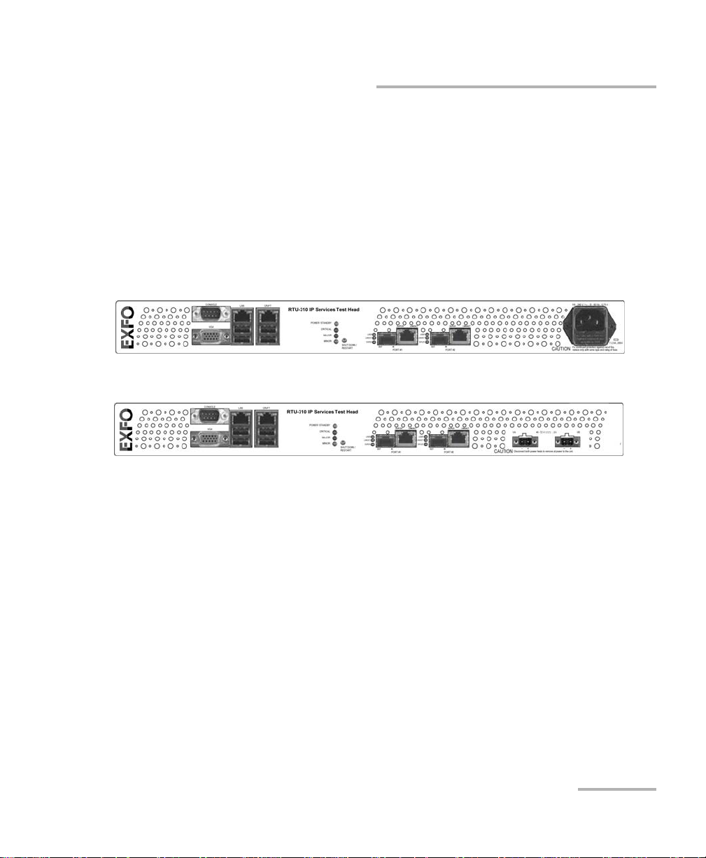
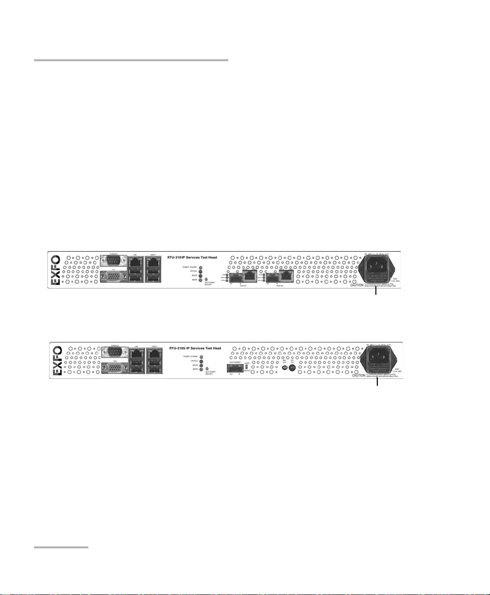
Models
The RTU-310 is equipped with two electrical 10/1000/1000 Mbps Ethernet
port and two optical 100/1000 Mbps Ethernet port. The RTU-310G is
equipped with one optical 10 Gbps Ethernet port. The RTU-310/310G unit is
available either with AC or DC power connector.
RTU-310
AC version
DC version
Models
Note: The 100 Mbps optical interface is available through a software option. Refer
to Software Options on page 347 for more information.
Note: A LAN transceiver is required for the 100/1000 Mbps optical port. See Optical
Transceivers (SFP) on page 5 for more information.
Ethernet Test Module 3
Page 16
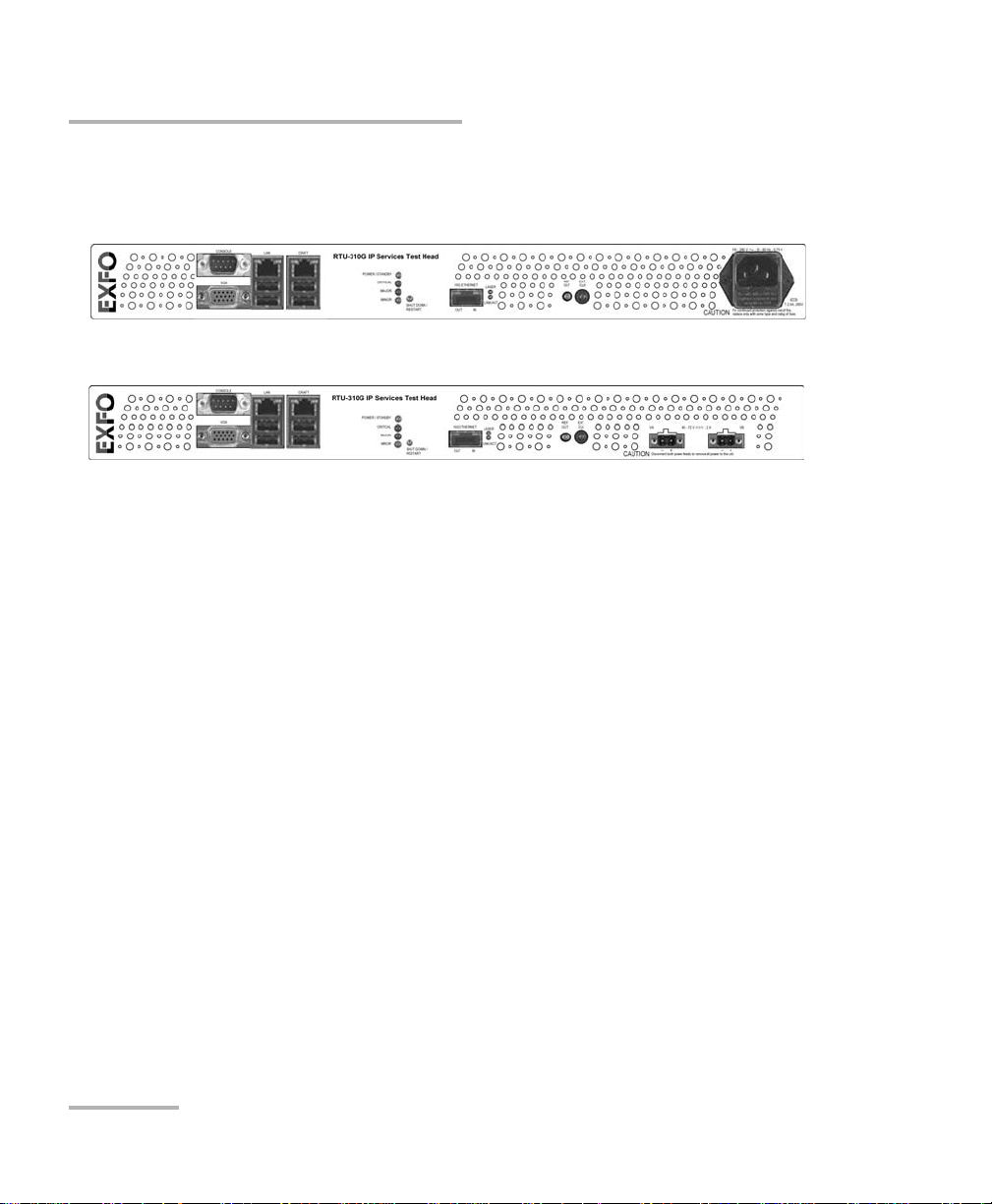
Introducing the RTU-310/310G
Models
RTU-310G
AC version
DC version
4 RTU-310/310G
Page 17

Introducing the RTU-310/310G
Option
Option Description
RTU-8580 Software key that enables the 1000 Mbps electrical
and optical interfaces on the RTU-310 model.
100M Optical Software key that enables the 100 Mbps optical
interface on the RTU-310.
Optical Transceivers (SFP)
Option Description
FTB-8590 1000Base-SX (850 nm) LC connectors optical SFP
transceiver module.
FTB-8591 1000Base-LX (1300 nm) LC connectors optical SFP
transceiver module.
Option
FTB-8592 1000Base-ZX (1550 nm) LC connectors optical SFP
transceiver module.
FTB-85910 100Base-FX (1310 nm, MMF, 2 Km) LC connectors
optical SFP transceiver module.
FTB-85911 100Base-LX10 (1310 nm, SMF, 15 Km) LC connectors
optical SFP transceiver module.
Ethernet Test Module 5
Page 18

Introducing the RTU-310/310G
Optical Transceivers (XFP)
Optical Transceivers (XFP)
Option Description
FTB-85900 850 nm short-wave optics (10GBASE-SR/SW)
FTB-85901 1310 nm long-wave optics (10GBASE-LR/LW)
FTB-85902 1550 nm long-wave optics (10GBASE-ER/EW)
6 RTU-310/310G
Page 19

Introducing the RTU-310/310G
Conventions
Conventions
Before using the product described in this manual, you should understand
the following conventions:
WARNING
Indicates a potentially hazardous situation which, if not avoided,
could result in death or serious injury. Do not proceed unless you
understand and meet the required conditions.
CAUTION
Indicates a potentially hazardous situation which, if not avoided,
may result in minor or moderate injury. Do not proceed unless you
understand and meet the required conditions.
CAUTION
Indicates a potentially hazardous situation which, if not avoided,
may result in component damage. Do not proceed unless you
understand and meet the required conditions.
IMPORTANT
Refers to information about this product you should not overlook.
Ethernet Test Module 7
Page 20

Page 21
2 Safety Information
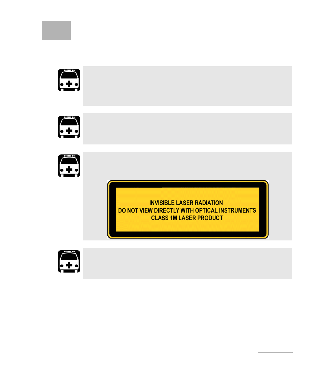
Laser Safety Warnings
WARNING
Do not install or terminate fibres while a laser source is active.
Never look directly into a live fibre, and ensure that your eyes are
protected at all times.
WARNING
Use of optical instruments with this product will increase eye
hazard.
WARNING
This product may employ a Class 1 or Class 1M SFP/XFP.
WARNING
When the LASER LED is on, the RTU-310/310G is receiving/emitting
an optical signal.
Ethernet Test Module 9
Page 22

Safety Information
Installation Instruction Warnings
Installation Instruction Warnings
No user serviceable parts are contained inside. Contact the
manufacturer regarding service of this equipment.
Keep all ventilation openings clear and unobstructed.
All wiring and installation must be in accordance with local building
and electrical codes acceptable to the authorities in the countries
where the equipment is installed and used.
CAUTION
CAUTION
IMPORTANT
CAUTION
Electrostatic Discharge (ESD) Sensitive Equipment: Electronic
equipment can be damaged by static electrical discharge. To
minimize the risk of damage, dissipate static electricity by touching
a grounded unpainted metal object before handling (or
removing/inserting) an SFP/XFP.
CAUTION
All telecom (electrical) interfaces are SELV (Safety Extra Low
Voltage) circuitry for intra-building use only.
10 RTU-310/310G
Page 23
Safety Information
Installation Instruction Warnings
IMPORTANT
Unauthorized modifications to this equipment shall void the user’s
authority to operate this equipment.
CAUTION
For DC version:
The RTU-310/310G must be installed in Restricted Access Locations.
Ethernet Test Module 11
Page 24

Page 25
3 Getting Started
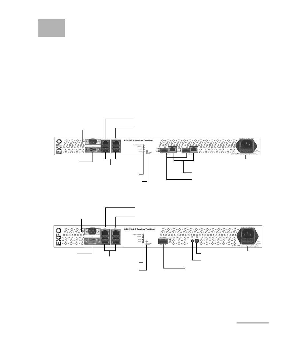
4 USB ports
Optical 100/1000 Mbps
AC Power Plug
10/100 Mbps Ethernet CRAFT Port
10/100 Mbps Ethernet LAN Port
Electrical 10/100/1000 Mbps
LEDs
SHUT DOWN/RESTART button
VGA port
Console Port
(future use)
4 USB ports
Optical 10 Gbps
AC Power Plug
10/100 Mbps Ethernet CRAFT Port
10/100 Mbps Ethernet LAN Port
LEDs
SHUT DOWN/RESTART button
Console Port
(future use)
VGA port
REF OUT
EXT. CLK
This chapter covers the description of the RTU-310/310G unit, the physical
installation, all connections, LEDs, and the initial setup of the
RTU-310/310G.
Front Panel Description
The following figure indicates the location of all connectors, ports, and
LEDs available on the front panel of the RTU-310/310G unit.
For RTU-310 AC version
For RTU-310G AC version
Ethernet Test Module 13
Page 26

Getting Started
SHUT DOWN / RESTART Button
SHUT DOWN / RESTART Button
The SHUT DOWN/RESTART button is used to either shut down or restart
(shut down and restart) the unit.
To shut down the RTU-310/310G unit:
Press the SHUT DOWN / RESTART button once. The RTU-310/310G unit
closes all applications and once done, the POWER/STANDBY LED will
flash to indicate that it is safe to disconnect the AC or DC power.
To wake up the RTU-310/310G unit:
Press the SHUT DOWN / RESTART button once while in standby mode.
The RTU-310/310G unit will restart. An LED sequence is displayed on
the RTU-310/310G front panel indicating the booting process. Once
powered up, the POWER/STANDBY LED turns on indicating that the
RTU-310/310G is ready to be used.
To reset the RTU-310/310G unit:
Press the SHUT DOWN / RESTART button for 5 seconds. The
RTU-310/310G unit will shut down without closing applications. Press
the SHUT DOWN / RESTART once again, an LED sequence is displayed
on the RTU-310/310G front panel indicating the booting process. Once
powered up, the POWER/STANDBY LED turns on indicating that the
RTU-310/310G is ready to be used.
14 RTU-310/310G
Page 27

Getting Started
RTU-310/310G LEDs
RTU-310/310G LEDs
LED Status Description
POWER/STANDBY On Indicates that the RTU-310/310G unit is on
and ready to be used.
Flashing Indicates that the RTU-310/310G unit is in
standby mode. It is safe to turn the unit off.
CRITICAL
MAJOR
MINOR
a. Alarm severity is configurable for certain alarms.
a
a
a
On Indicates current critical severity alarm.
Off Indicates no critical severity alarm.
On Indicates current major severity alarm.
Off Indicates no major severity alarm.
On Indicates current minor severity alarm.
Off Indicates no minor severity alarm.
VGA Port
The VGA port is used to connect a monitor to access the EX-Vu application
on the RTU-310/310G platform.
Console Port
The Console port is provided for future use.
USB Ports
The RTU-310/310G provides four USB ports. These ports are used to
connect keyboard, mouse, or to boot from a USB drive.
Ethernet Test Module 15
Page 28
Getting Started
Installing the RTU-310/310G in a Rack
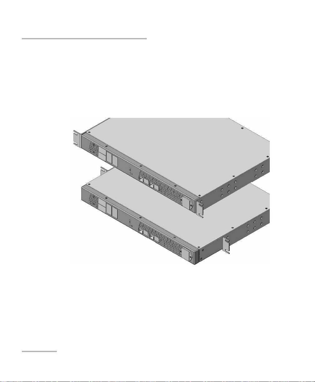
Installing the RTU-310/310G in a Rack
To install the RTU-310/310G in a rack:
1. Fix the supplied brackets on the RTU-310/310G with the supplied
8-32 x 5/16 in. screws.
Bracket kits are available for 19 and 23 inch rack mount applications
but only one kit is supplied with the unit.
Note: The brackets allow the RTU-310/310G to be installed with its front panel
flush or offset with the front of the rack.
16 RTU-310/310G
Page 29
Getting Started
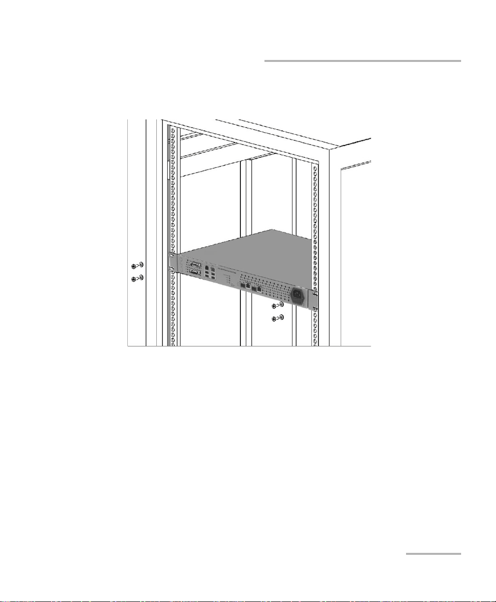
Installing the RTU-310/310G in a Rack
2. Place the unit in the rack at the desired height.
3. Fix the unit in place using four 10-32 x 1/2 in. screws and lock washers.
Ethernet Test Module 17
Page 30
Getting Started
AC Power Plug
AC Power Plug
Connecting the Power
Connecting the Power
The RTU-310/310G is available with either an AC or DC integrated power
supply.
Note: The RTU-310/310G automatically powers up once connected to a live AC or
DC power source.
To connect the RTU-310/310G to an AC power source:
1. Connect the supplied AC power cord to the RTU-310/310G front panel.
2. Connect the other end to an AC power source.
For RTU-310
For RTU-310G
18 RTU-310/310G
Page 31

Getting Started
Ground lug
Connecting the Power
To connect the RTU-310/310G to a DC power source:
WARNING
The RTU-310/310G DC version is intended to be grounded. Ensure
that the unit is connected to earth ground during normal use.
1. Remove the two Phillips flat screws, and remove the ground lug on the
back panel of the RTU-310/310G unit.
2. Use a #6 AWG wire (not supplied) insert the wire into the lug and
crimp it.
3. Use the two Phillips flat screws to attach the ground lug and wire
assembly to the rear panel of the RTU-310/310G unit.
4. Connect the other end to the ground distribution network.
Ethernet Test Module 19
Page 32

Getting Started
Supplied lug
Positive ( + ) supply
wire lead
Negative ( - ) supply
wire lead
Supplied lug
Positive ( + ) supply
wire lead
Negative ( - ) supply
wire lead
Connecting the Power
5. Using 14-16 AWG copper insulated wires and the supplied lug, insert
the two stripped wires into the lug and tighten the screws firmly. Make
sure to respect the polarity.
The positive supply wire lead (40-70V) must be on the right side of the
lug and the negative supply wire on the left side.
For RTU-310
For RTU-310G
6. Connect the lug to one of the two DC input lugs on the RTU-310/310G
unit and tighten the screws firmly.
20 RTU-310/310G
Page 33

Getting Started
Turning the Unit On
7. Connect the other end of wires to the DC power source.
CAUTION
The DC input feeds to the equipment must be protected by 20A
rated maximum breaker provided as part of the building
installation.
8. To add a redundant DC source on the RTU-310/310G, repeat steps 5
to 7.
Turning the Unit On
To turn the unit on:
Connect the RTU-310/310G to a live AC or DC power source.
Note: The RTU unit must be connected to monitor and keyboard before switching
it on.
An LED sequence is displayed on the RTU-310/310G front panel
indicating the booting process. Once powered up, the
POWER/STANDBY LED turns on indicating that the RTU-310/310G is
ready to be used.
Automatic Power Failure Recovery
In the case of a power failure, the RTU-310/310G unit will recover
automatically when the power is restored. The RTU-310/310G unit will
return to the same state as before the power failure.
Ethernet Test Module 21
Page 34

Getting Started
Electrical 10/100/1000 Mbps
Connecting the Test Interface Ports
Connecting the Test Interface Ports
Connecting the Electrical 10/100/1000 Mbps
Ethernet Test Interface
The RTU-310 unit provides two electrical RJ-45 ports for10Base-T,
100Base-T, or 1000Base-T testing capability.
Note: 1000Base-T is optional.
For RTU-310
To use the electrical 10/100/1000 Mbps Ethernet interface for
testing:
Connect the 10/100/1000 Mbps electrical signal using a CAT 5
unshielded cable (with an RJ-45 connector) to the 10/100/1000 Mbps
port of the RTU-310 unit.
Note: Port connector type is RJ-45 for category 5 unshielded twisted pair (UTP)
connection. Refer to Ethernet Cables on page 455 for cable specifications.
22 RTU-310/310G
Page 35

Electrical Port LEDs
LED Status Description
LINK/ACT On Ethernet link up
Off Ethernet link down
Flashing TX/RX activity
DUPLEX On Full Duplex mode
Off Half Duplex mode
Flashing Collisions detected
Getting Started
Connecting the Test Interface Ports
Ethernet Test Module 23
Page 36

Getting Started
Optical 100/1000 Mbps
Optical 10 Gbps
Connecting the Test Interface Ports
Connecting the Optical 100/1000 Mbps and 10
Gbps Ethernet Test Interfaces
The RTU-310 unit provides two optical ports for 100Base-FX or 1000Base-X
whereas the RTU-310G provides one optical port for 10 Gbps Ethernet
testing capability. The optical port for RTU-310 is Small Form Factor
Pluggable (SFP) slot type (LC connector) and the optical port for RTU-310G
is Extended Small Form Pluggable (XFP) slot type.
Note: 100Base-FX and 1000Base-X are optional.
For RTU-310
For RTU-310G
24 RTU-310/310G
Page 37

Getting Started
Connecting the Test Interface Ports
To use the optical 100/1000 Mbps Ethernet interface for testing:
1. Insert one of the following SFP modules into the optical slot.
Rate Description
1000Base-X 850 nm SFP module for 1000Base-SX short
wavelength laser connection.
1300 nm SFP module for 1000Base-LX long
wavelength laser connection.
1550 nm SFP module for 1000Base-ZX extended
wavelength laser connection.
100Base-FX 1310 nm SFP module for 100Base-FX, MMF, 2 Km.
1310 nm SFP module for 100Base-LX10, SMF, 15 Km.
Ethernet Test Module 25
Page 38

Getting Started
Connecting the Test Interface Ports
2. Carefully connect optical fiber cables to the SFP’s or XFP’s IN and OUT
ports.
To ensure good signal quality, make sure that the optical fibre
connector is fully inserted into the optical connector port.
Note: In order not to exceed the maximum receiver power level before damage,
an attenuator must be used. Refer to Maximum RX before damage (dBm)
on page 453 for more information.
Optical Port LEDs for RTU-310
LED Status Description
LASER On An optical signal is generated
Off No optical signal is generated
LINK/ACT On Ethernet link up
Off Ethernet link down
Flashing TX/RX activity
DUPLEX On Full Duplex mode
Off Half Duplex mode
Flashing Collisions are detected in half duplex mode
26 RTU-310/310G
Page 39

Connecting the Test Interface Ports
Optical Port LEDs for RTU-310G
LED Status Description
LASER On An optical signal is generated
Off No optical signal is generated
LINK/ACT On Ethernet link up
Off Ethernet link down
Flashing TX/RX activity
Getting Started
Ethernet Test Module 27
Page 40

Getting Started
10/100 Mbps Ethernet CRAFT Port
10/100 Mbps Ethernet CRAFT Port
Connecting the Management Interfaces
Connecting the Management Interfaces
Connecting the Ethernet CRAFT Port
Connecting a PC to the Ethernet CRAFT port is required to access the user
interface and configure the RTU-310/310G the very first time.
Note: The CRAFT port is for access using a Static configured IP.
To connect locally to the RTU-310/310G using the CRAFT port:
Connect a PC (running the Ex-Vu application) to the CRAFT port using
a standard straight through Ethernet cable with an RJ-45 connector.
Refer to Ethernet Cables on page 455 for more information.
The CRAFT port is configured with a static IP address 10.10.10.10. Local
connectivity (LAN IP Address, unit clock, etc.) to the unit is required to
configure the RTU-310/310G settings for the first time. Using Ex-Vu
connect locally to the RTU-310/310G provides you full access to all the
test and configuration functions to the unit. Refer to To log on to the
RTU-310/310G interface using SUI: on page 37, for more information.
For RTU-310
For RTU-310G
28 RTU-310/310G
Page 41

CRAFT Port Embedded LEDs
LED Status Description
Getting Started
Connecting the Management Interfaces
LINK/ACT
(Green)
SPEED
(Yellow)
On Ethernet link up
Off Ethernet link down or no activity
Flashing TX/RX activity
On 100 Mbps
Off 10 Mbps
Ethernet Test Module 29
Page 42

Getting Started
10/100 Mbps Ethernet LAN Port
10/100 Mbps Ethernet LAN Port
Connecting the Management Interfaces
Connecting the Ethernet LAN Port
The RTU-310/310G LAN interface is designed to provide remote
connectivity to the unit through a typical management network.
To connect remotely to the RTU-310/310G:
Both the RTU-310/310G unit and remote PC must be connect to the
same management network using standard straight through Ethernet
cables with RJ-45 connectors. Refer to Ethernet Cables on page 455 for
more information.
The remote PC must be running the EX-Vu remote application. Refer to
To log on to the RTU-310/310G interface using SUI: on page 37 or
Connect to the RTU-310/310G using TightVNC: on page 474 for more
information.
For RTU-310
For RTU-310G
Note: The LAN port is by default set to acquire the IP address from a DHCP
network device. It can alternatively be configured to use a static IP address
if required.
30 RTU-310/310G
Page 43

LAN Port Embedded LEDs
LED Status Description
Getting Started
Connecting the Management Interfaces
LINK/ACT
(Green)
SPEED
(Yellow)
On Ethernet link up
Off Ethernet link down or no activity
Flashing TX/RX activity
On 100 Mbps
Off 10 Mbps
Ethernet Test Module 31
Page 44

Getting Started
Software Management
Software Management
Software management functionality ensures that the version of EX-Vu
running on the RTU-310/310G unit and the client machine is the same.
Software Version Management using EX-Vu
When the version of EX-Vu remote application does not match with the
RTU-310/310G software load, options to download and match the software
version are displayed.
You can choose the following options:
Match the version of EX-Vu remote application to the current version of
RTU-310/310G software load
Match the version of RTU-310/310G software load to the current version
of EX-Vu remote application
32 RTU-310/310G
Page 45

Getting Started
Software Management
To match the version of Ex-Vu to the current version of the
RTU-310/310G software load:
1. Select Download and install the EX-Vu remote application to match
the current RTU-310 version and click OK.
The current EX-Vu remote application is uninstalled and the other
version of EX-Vu application is downloaded from the RTU-310/310G
and installed on the client machine to match the version of the
RTU-310/310G software load.
2. Click Next and follow the instruction on the screen to complete the
installation of the EX-Vu remote application.
To match the version of RTU-310/310G software load to the
current version of EX-Vu remote application:
1. Select Download and install the RTU-310 software load to match
the current EX-Vu version and click OK.
A message is displayed to confirm that you want to download the
RTU-310/310G software load.
Ethernet Test Module 33
Page 46

Getting Started
Software Management
2. Click Ye s to confirm the download
The current RTU-310/310G software load is uninstalled and the other
version of the software is downloaded from the client machine and
installed on the RTU-310/310G unit.
Note: If the version of RTU-310/310G software load (that needs to be installed to
match the EX-Vu version) is not available on the client machine, a rollback
is initiated by the RTU-310/310G unit. In the rollback process, the
uninstalled version of the RTU-310/310G software load is reinstalled.
Software Version Management using TightVNC
The TightVNC service is provided as a part of the RTU-310/310G software
package. In addition to EX-Vu, the TightVNC service can be used to control
the RTU-310/310G. It is used to transfer files from the client machine to the
RTU-310/310G and vice versa. To connect to the RTU-310/310G unit using
TightVNC, the client machine must have TightVNC service installed. Refer
Remote Connection using TightVNC on page 474, for more information.
Note: Unlike EX-Vu, installation of the newly transferred software on the RTU and
the client machine must be done manually. After the installation, when the
software versions of the RTU-310/310G and the client machine match, then
the remote EX-Vu session can be launched. Alternatively, the RTU-310/310G
can be controlled from the Client machine by the TightVNC Service.
34 RTU-310/310G
Page 47

Getting Started
Software Management
To transfer files to the RTU-310/310G:
1. Create a folder on the local drive of the RTU-310/310G.
2. Right-click the task bar of the TightVNC Viewer screen and select
Transfer files.
3. Select the setup files on the local drive of your computer and click the
button.
The files are transferred to the local drive of the RTU-310/310G.
4. Double-click the setup file RTU-310/310G setup.exe. Click Next to start
the installation and follow the on-screen instructions. You can also
refer the release notes that came with your product for more
information.
Ethernet Test Module 35
Page 48

Page 49

4 Introducing the Smart User
Interface
To Start the RTU-310/310G Application:
1. Once your RTU-310/310G module is installed, turn on the
RTU-310/310G.
2. In the main window, under Modules, press RTU-310/310G once to
select the module.
3. start the Smart User Interface (SUI).
Login
Ensure that the RTU-310/310G is connected to the management network or
you are locally connected to the RTU-310/310G.
To log on to the RTU-310/310G interface using SUI:
1. Double-click the RTU-310 or RTU-310G icon on the desktop.
2. Enter the IP address or Hostname for the RTU platform.
3. Click Connect.
Ethernet and Fibre Channel Application 37
Page 50

Introducing the Smart User Interface
Login
Note: An error is displayed when the connection to the RTU-310/310G unit is not
established, the initialization of the SUI software fails, or due to an
unexpected loss of connection.
Note: Alternatively, you can connect to the RTU-310/310G using the TightVNC
service. Refer Remote Connection using TightVNC on page 474, for more
information.
A check is performed to ensure that the version of SUI software on the
RTU-310x and client machine match. Refer to Software Management on
page 32 for more information.
38 FTB-8500 Series and FTB-8120NGE/8130NGE
Page 51

Main Window
Application name
Minimize
Help
Exit
Ta bs
Ta b( s )
Ta b’ s
Content
Te s t co n t ro l s
Date and time
Remote
status
Global Test Status
Introducing the Smart User Interface
Main Window
Ethernet and Fibre Channel Application 39
Page 52

Introducing the Smart User Interface
Main Window
Tabs
The SUI application contains the following four main application tabs that
contain other tabs.
TEST Tab
The TEST tab gives access to the test creation, configuration, and
results.
Note: Only the Setup tab is available when there is no test created.
Setup tab is part of the TEST tab and allows setting up the test. Refer to
page 68 for more information.
Once the test is created, other tabs containing one or two tabs are
enabled allowing configuration of test parameters and viewing of the
test status and results.
40 FTB-8500 Series and FTB-8120NGE/8130NGE
Page 53

Introducing the Smart User Interface
Port 1
Port 2
Main Window
For Dual ports (RTU-310 only), see the figure below for the localization
of the port number on each tabs.
In this user guide, the tabs are grouped as shown below:
Summary Tabs on page 121
Por t Tabs on page 133
Stream Generation Tabs on page 161
Stream Analyzer Tabs on page 195
Traffic Analyzer Tabs on page 199
IPTV Tabs on page 249 (RTU-310)
Patter n Ta bs on page 289
RFC 2544 Tabs on page 295
EtherSAM Tabs on page 321
Ethernet and Fibre Channel Application 41
Page 54

Introducing the Smart User Interface
Main Window
TCP Throughput Tabs on page 349RTU-310)
Advanced Tab on page 355
WIS Tabs on page 239 (RTU-310G)
Common Tab on page 359
Expert Mode Tabs on page 363
System tab; refer to page 333 for more information.
Too ls tab; refer to page 407 for more information.
About tab; gives information on EXFO company, contact, and product
software release version.
Application Title
Displays the software application title.
Minimize
The minimize button ( _ ) allows minimization of SUI application.
Help
The help button ( ? ) displays the help
information on the current window. A
window pops up to select the area of the
application where help is required. Click
OK and the help information is
immediately displayed.
42 FTB-8500 Series and FTB-8120NGE/8130NGE
Page 55

Introducing the Smart User Interface
Main Window
It is also possible to navigate through the help information once the help
window is open.
Exit
The exit button ( X ) closes the current application.
Ethernet and Fibre Channel Application 43
Page 56

Introducing the Smart User Interface
Global Test Status and Controls
Global Test Status and Controls
Global Test Status
The global test status area displays the alarm, verdict, and test timer.
Clicking on this area maximizes the view of these status. The maximized
view is useful to facilitate distant viewing of these status.
To minimize the view, either click on the global test status area or click
anywhere on the maximized status area.
H (History): Indicates that alarms/errors occurred in the past. A grey
background indicates that the test did not run yet, a green background
indicates that no alarm/error has occurred, while a red background
indicates that at least one alarm/error has occurred.
44 FTB-8500 Series and FTB-8120NGE/8130NGE
Page 57

Introducing the Smart User Interface
Global Test Status and Controls
Current status: Indicates the current alarm/error status of the test. A
grey background indicates that the test is not running (--), a green
background indicates that there is no alarm/error (NO ALARM), while
a red background indicates that at least one alarm/error condition has
occurred in the last second (ALARM).
Note: The history and current alarm/error status are monitored once the test is
started.
Verdict: Gives the verdict, PA SS (green background) or FAIL (red
background) of the test according to the defined threshold settings.
Verdict is only displayed with EtherSAM, RFC 2544, and BERT tests. For
RFC 2544 and BERT tests, at least one of the Enable criteria check
boxes must be selected. Refer to EtherSAM Tabs on page 321 or to
Expert Mode Tabs on page 363 (RFC 2544 and BERT tests) for more
information.
The test timer indicates the time elapsed since the beginning of the
test. The test timer format is day hour:minute:second.
Test Cont rols
Button Description
Start: Starts the test. Start is available when the test is created and not running.
a
Stop
: Stops the test.
H. Reset
Reset
(H) and current (C) LEDs for the entire test case. Also resets the logger.
Report
page 50 for more information.
New
the test.
Ethernet and Fibre Channel Application 45
a
: Resets the history (H) alarm and error LEDs.
a
: Resets counters (seconds, count, and rate), test timer and both history
b
: Generates a report of the current test. See Test Report Generation on
b
: Clears the current test. A user’s confirmation is required before clearing
Page 58

Introducing the Smart User Interface
Global Test Status and Controls
Button Description
Loadb: Loads a previously saved configuration. Select an existing file and click
Open to confirm. The default directory is
C:\ProgramFiles\EXFO\Applications\RTU\310\UserFiles\Configuration or
C:\ProgramFiles\EXFO\Applications\RTU\310G\UserFiles\Configuration. The
configuration file extension is cfg.
An error message is displayed and the configuration is not loaded when the file
is corrupted, the module is not properly installed, the hardware or software
options are not compatible, or when the resources or power are not sufficient.
b
Save
: Saves the current test configuration. Select an existing file, or type a new
name in the File name field, and click Save. The default directory is
C:\ProgramFiles\EXFO\Applications\RTU\310\UserFiles\Configuration or
C:\ProgramFiles\EXFO\Applications\RTU\310G\UserFiles\Configuration.
a
Send
: Generates pattern bit error according to the amount selected on the
Pattern TX tab. Refer to Pattern Error Injection on page 292. This button is only
available with BERT test.
a
Set
: Allows selecting the port that will be used for pattern bit error injection.
See Send button for error injection. This button is only available with BERT test
in Dual Ports topology. Available with RTU-310 only.
Laser Off (grey): Indicates that the laser control is off. Clicking this button will
activate the laser immediately by emitting an optical laser signal. This button is
only available for optical interfaces. The laser is On by default when the test is
created unless otherwise set from the Default/Ethernet Test Preferences on
page 336.
Laser On (green): Indicates that the laser control is on. Clicking this button will
turn off the laser. This button is only available for optical interfaces. The laser is
On by default when the test is created unless otherwise set from the
Default/Ethernet Test Preferences on page 336. The laser control button is not
affected when turning off the laser by generating a LOS for example.
Favorites
b
: Provides access to 10 default or customer defined test case
configurations. See Favorites on page 48 for more information.
a. Only available when the test is running.
b. Only available when the test is not running (Stop).
46 FTB-8500 Series and FTB-8120NGE/8130NGE
Page 59

Introducing the Smart User Interface
Global Test Status and Controls
Date and Time
Indicates the date (YYYY-MM-DD) and time (HH:MM:SS).
Refer to Time Options on page 334 for more information on time format
and time zone.
System Alarms
The System alarms provide a quick indication about the alarm status of the
RTU-310/310G unit.
H (History) LED: Indicates the alarms/errors that occurred in the past.
A green LED indicates that no alarm/error has occurred, while a red
LED indicates that at least one alarm/error has occurred.
C (Current) LED: Gives the current status of the alarm/error. A green
LED indicates that there is no alarm/error, while a red LED indicates
that at least one alarm/error condition has occurred in the last second.
Refer to System Alarms on page 367 , for more information on the type of
alarms/errors encountered on the RTU-310/310G unit.
Ethernet and Fibre Channel Application 47
Page 60

Introducing the Smart User Interface
Favorites
Favorites
Favorites gives access to 10 factory test case configurations. Favorites is
available when no test is running.
Click .
Favorites List
Allows to select a test case configuration. The test case configuration
selected by default is the first one in the list.
Note: Test cases not supported by the current RTU-310/310G model and its
options will not be created.
Note: Favorites may or may not be compatible from one version of software to
another.
48 FTB-8500 Series and FTB-8120NGE/8130NGE
Page 61

Introducing the Smart User Interface
Favorites
Overwrite Selected Favorite Content
The factory test case configurations can be modified as well as their
default names.
Favorite Name: Allows changing the name of the test case
configuration file. A maximum of 32 characters are allowed in the
name.
Save: Saves the current test case configuration using the specified
favorite name.
Load
Loads the selected test case configuration. Loading a favorite configuration
automatically clears the current test case.
Factory Default
Restores the factory default favorites list based on the enabled options.
Note: The favorites list is not updated when a new software option is installed.
For this reason, the Factory Default button allows to recreate the favorites
list based on the current options.
Close
Closes the Fav orites window.
Ethernet and Fibre Channel Application 49
Page 62

Introducing the Smart User Interface
Test Report Generation
Test Report Generation
Click Report from the Global Test Status and Controls to generate a report
for the current test. The report contains all the information about the test
including the job information, system information, interface setup, test
summary, test configuration, results, etc.
Note: Nothing prevents the configuration and alarm/error injection setup while
the test has been stopped; thus, the report should be saved before changing
any test parameters to avoid discrepancy between the configuration and
results.
Information Tab
Job Information: These parameters are used to identify the
source of the report and are not mandatory. Enter the following job
information if required: Job ID, Contractor, Customer, Operator
Name, and Comment. Up to 256 characters are allowed for each
parameter.
50 FTB-8500 Series and FTB-8120NGE/8130NGE
Page 63

Introducing the Smart User Interface
Test R e po rt Gene r a ti on
Report Settings: These parameters are used to identify the report
and are not mandatory. Enter the following report information if
needed: Report Title, Report Header, Selected Logo, and Report
Format.
Click Browse to select a different logo, then click Open.
Report Format: Select the report file format. Choices are html, csv,
pdf, and txt. The CSV format (comma separated file format)
generates a report with comma delimiter for English OS and
semicolon for other OS languages. The default setting is html..
View Report After Generation: Allows displaying the report once
it is generated. However, the report can only be displayed when
the Windows application supporting the selected Report Format is
installed. The View Report After Generation check box is not
selected by default.
Note: Once generated, the report file can manually be opened typically using
Windows Explorer. The default directory is
C:\ProgramFiles\EXFO\Applications\RTU\310\UserFiles\Reports or
C:\ProgramFiles\EXFO\Applications\RTU\310G\UserFiles\Reports.
Note: If the html report contains special characters, please make sure that the
encoding in your Web browser is set to Western European ISO. To set the
encoding to Western European ISO, right click the report from Internet
Explorer, select Encoding, and select Western European ISO.
Default button: Click Default to restore the default report settings.
Ethernet and Fibre Channel Application 51
Page 64

Introducing the Smart User Interface
Test Report Generation
Generate button: Allows generating and saving the report. Select
an existing file, or type a new name in the File name field and click
OK. The default directory is
C:\ProgramFiles\EXFO\Applications\RTU\310\UserFiles\Reports or
C:\ProgramFiles\EXFO\Applications\RTU\310G\UserFiles\Reports.
The report file can be saved on the following locations:
Local memory (RTU-310/310G): The file is saved locally on the
RTU-310/310G memory.
Network drive: The file is saved on a network drive.
USB drive or Compact Flash: The file is saved on a removable
drive.
Close button: Closes the report generation settings window.
52 FTB-8500 Series and FTB-8120NGE/8130NGE
Page 65

Introducing the Smart User Interface
Test R e po rt Gene r a ti on
Sections Tab
Pre-defined selection: Allows selecting the type of report, and the
window underneath allows selecting what will be part of the
report. The default setting is Summary Report. Choices are:
Summary Report selects the Summary report section only.
Test Case Report selects all the report sections.
Note: Once the report type is selected, each section can be selected to customize
the report.
The Select All and Deselect All buttons are used to respectively select
or deselect all the report sections.
Ethernet and Fibre Channel Application 53
Page 66

Introducing the Smart User Interface
Typi c a l Ta b Elem e n ts
Typical Tab Elements
Once the test is created, different tabs are available allowing test
configuration and monitoring. The following section describes usual
elements appearing on those tabs.
Status LEDs
H (History) LED: Indicates that alarms/errors occurred in the past. A
grey LED indicates that the test did not run yet, a green LED indicates
that no alarm/error has occurred, while a red LED indicates that at
least one alarm/error has occurred in the test.
C (Current) LED: Gives the current status of the alarm/error. A grey LED
indicates that the test is not running, a green LED indicates that there is
no alarm/error, while a red LED indicates that at least one alarm/error
condition has occurred in the last second.
Note: The H and C LEDs are updated every second.
54 FTB-8500 Series and FTB-8120NGE/8130NGE
Page 67

Introducing the Smart User Interface
Alarm/Error Measurements
Note: Alarms/Errors are only monitored once the test is started.
Seconds: Gives the total number of the seconds in which one or more
alarm/error occurred.
Count: Gives the number of occurrences of a specific error. The count
is displayed using integer value; exponential value (1.00000E10) is used
when the count is bigger than the field display capacity.
Rate: Calculates and displays the error rate. The rate is expressed using
the exponential format with two decimal digits (example: 1.23E-04).
Arrow Buttons
Button Description
Top arrow: Moves to the top of the list.
Typical Tab Elements
Page up arrow: Moves one page up.
Up arrow: Moves one event up.
Down arrow: Moves one event down.
Page down arrow: Moves one page down.
End arrow: Moves to the end of the list.
Ethernet and Fibre Channel Application 55
Page 68

Introducing the Smart User Interface
Ta b l e S o r t
Typi c a l Ta b Elem e n ts
Table Sorting
Tables offer sorting capabilities on one or more columns.
An arrow next to the column label name, indicates the sorting column field
and the sorting order. Clicking again on the selected sort column label will
change the sort order.
Clicking another column label allows to sort using a different field.
56 FTB-8500 Series and FTB-8120NGE/8130NGE
Page 69

Introducing the Smart User Interface
Tab Configuration buttons
Top t ab
Page/Tab
Bottom
tab
Tab Configuration
Tab Configuration
Once the test is created, other tabs next to the Test tabs are enabled
allowing configuration of test parameters and viewing of the test status and
results.
A tab configuration button is available at the top-right part of each tab.
Ethernet and Fibre Channel Application 57
Page 70

Introducing the Smart User Interface
Tab Configuration
This tab configuration window allows configuration of all tabs on any page
except for the Te st Se tup, and Summary tabs. The tab configuration allows
also to jump directly to the desired page by selecting it from the Defined
Tab s list and then clicking OK.
Selected Tab
Tab N ame indicates the name of the tab containing the two tabs (top
and bottom page). Clicking this field allows changing the tab name.
Tab name can be up to 35 characters long including the “/” and spaces.
Top Pag e indicates the tab displayed at the top of the tab.
Bottom Page indicates the tab displayed at the bottom of the tab.
58 FTB-8500 Series and FTB-8120NGE/8130NGE
Page 71

Introducing the Smart User Interface
Tab Configuration
Defined Tabs
Allows the selection of a tab.
Up and down arrows are used to respectively move the selected page up
or down in the list.
Insert button allows the insertion of a new tab after the selected tab (the
one highlighted) A maximum of 30 tabs can be displayed.
Delete button allows the deletion of the selected tab.
Page Selection
Typ e: Allows the selection of a tab that will be assigned to the selected
tab when clicking either Apply to top page or Apply to bottom page.
Path: Indicates the test signal structure (layers/nodes of the test case)
corresponding to the selected tab. Refer to Introducing the Test Setup
on page 68 for more information on test layers/nodes.
Apply To Top Page: Applies the selected tab as top of page for the
selected tab.
Apply To Bottom Page: Applies the selected tab as bottom of page for
the selected tab.
Note: The available tabs listed are a function of the test path activated Empty Tab
displays a blank tab (Tabs that are not populated are left blank). Te st
Setup and Summary tabs cannot be duplicated, deleted, or renamed.
Ethernet and Fibre Channel Application 59
Page 72

Introducing the Smart User Interface
Tab Configuration
Help Button (?)
Displays the help information related to the tab configuration. It is also
possible to navigate through the remainder of the help information.
Default Button
Return to the default page configuration layout.
OK Button
Accepts the page layout changes and jumps to the selected page (Defined
tabs).
Cancel Button
Cancels the changes and returns to the page from where the tab
configuration was launched.
60 FTB-8500 Series and FTB-8120NGE/8130NGE
Page 73

Introducing the Smart User Interface
Keyboard Usage
Keyboard Usage
The SUI pops up different keyboards to modify data. Following are the
usual keyboard keys:
Left arrow: Moves the cursor one position to the left.
Right arrow: Moves the cursor one position to the right.
Del: Deletes the value at the cursor position.
Back: Deletes the value preceding the cursor position.
Help: Displays the help information related to the keyboard usage.
It is also possible to navigate through the help information.
OK and Enter: Completes data entry.
Cancel: Closes the keyboard and discards the keyboard entry.
Binary keyboard: Allows entering 0 and 1 values.
Ethernet and Fibre Channel Application 61
Page 74

Introducing the Smart User Interface
Keyboard Usage
Numerical keyboards: Allows entering integer/decimal values.
For integer unsigned or signed values
For rate values: Allows entering the rate values (0 through 9, and
exponent)
For IP address, Subnet Mask and Default Gateway values
62 FTB-8500 Series and FTB-8120NGE/8130NGE
Page 75

Introducing the Smart User Interface
Keyboard Usage
Time Keyboard: Allows entering a time value.
Date keyboard: Allows selecting a date by clicking the date on the
calendar. Use the left and right arrow to switch from one month to
another or Click the month area for quick month selection. Click the
year area for quick year selection.
Ethernet and Fibre Channel Application 63
Page 76

Introducing the Smart User Interface
Keyboard Usage
Hexadecimal keyboards: Allows entering hexadecimal values
(0 through 9 and A through F)
For MAC address
For IPv6 address
64 FTB-8500 Series and FTB-8120NGE/8130NGE
Page 77

Introducing the Smart User Interface
Keyboard Usage
Full keyboard: Allows entering numbers, letters and some other
characters. The Back, Del, Shift and space bar keys have the same
functionality as a regular PC keyboard.
Trace message keyboard (WAN): Allows entering alphanumerical
characters (ITU T.50) required for J0 and J1 Trace fields. Click the
Ctrl Char button to access these characters.
Ethernet and Fibre Channel Application 65
Page 78

Introducing the Smart User Interface
Keyboard Usage
ITU T.50 Characters
b7 to b1 Character Description b7 to b1 Character Description
000 0000 NUL Null 001 0000 DLE Data Link Escape
000 0001 SOH Start Of Heading 001 0001 DC1 Device Control 1
000 0010 STX Start of Text 001 0010 DC2 Device Control 2
000 0011 ETX End of Text 001 0011 DC3 Device Control 3
000 0100 EOT End Of Transmission 001 0100 DC4 Device Control 4
000 0101 ENQ Enquiry 001 0101 NAK Negative
Acknowledge
000 0110 ACK Acknowledge 001 0110 SYN Synchronous idle
000 0111 BEL Bell 001 0111 ETB End of Transmission
Block
000 1000 BS Backspace 001 1000 CAN Cancel
000 1001 HT Horizontal
001 1001 EM End of Medium
Tab ul at io n
000 1010 LF Line Feed 001 1010 SUB Substitute character
000 1011 VT Vertical Tabulation 001 1011 ESC Escape
000 1100 FF Form Feed 001 1100 IS4 Information
Separator 4
000 1101 CR Carriage Return 001 1101 IS3 Information
Separator 3
000 1110 SO Shift-Out 001 1110 IS2 Information
Separator 2
000 1111 SI Shift-In 001 1111 IS1 Information
Separator 1
66 FTB-8500 Series and FTB-8120NGE/8130NGE
Page 79

5 Creating and Starting a
Test Case
A test case can be created using one of the following methods:
Test S etup allows the creation of the test case by travelling through the
signal structure. See Introducing the Test Setup on page 68.
See Test Case Availability to determine the test cases supported by the
unit.
Load allows setting up the test case by loading a previously saved
configuration. Refer to Load on page 46 for more information.
Script allows running a script that creates the test case. Refer to Script
on page 408.
Ethernet and Fibre Channel Application 67
Page 80

Creating and Starting a Test Case
Data Path
Selector
Configuration
section
Te s t Set u p
Controls
Introducing the Test Setup
Introducing the Test Setup
The Test S etup window is displayed by default when the SUI is started. In
the case where the SUI is not in the test setup window, click the Test Setu p
from the TEST Tab on page 40.
Tree allows seeing the configuration test structure (data path).
Grid is used for test case direction (decoupled test mode).
Data Path Selector is used to select the datapath structure (for
example: port, signal, Pattern, etc.) of the test case.
Configuration section allows parameters configuration for each node
of the test.
Test Na me represents the name of the test connection used to identify
the test. The default setting is TEST.
Note: The other configuration section parameters are described for each specific
test.
68 FTB-8500 Series and FTB-8120NGE/8130NGE
Page 81

Creating and Starting a Test Case
Introducing the Test Setup
Test Se tup C ont r ols :
Back returns to the previous configuration step allowing to see,
change or delete what had been selected.
Next switches to the next configuration step. The Next button is
only available when selection(s) from the Data Path Selector
and/or the Grid has been made.
Delete deletes the current path node.
Finish/Setup:
Finish completes the configuration and creates the test case. The
current window settings are only accepted if the selection has
been made from the Grid view. Default parameters will be used
for the remaining wizard steps. Thus, clicking Finish for BERT test
will automatically add a pattern at the end of the test case structure
if not already selected.
Setup is displayed instead of Finish once the test is created
allowing to return in setup mode. Setup is not available when the
test is started (running).
Ethernet and Fibre Channel Application 69
Page 82

Creating and Starting a Test Case
Introducing the Test Setup
The test path is created through the configuration of each layer that must
be crossed by the signal under test. The test path can contain the following
steps depending on the test application type:
For RTU-310:
For RTU-310G:
70 FTB-8500 Series and FTB-8120NGE/8130NGE
Page 83

Creating and Starting a Test Case
Introducing the Test Setup
Steps
The Test step is the root of the test case. It allows the configuration
Available with
All tests
of the test name, test application type, Interface Type, topology, and
Clock Mode. For RFC 2544, the selection of the sub tests and dual
test set are also available.
The Port step allows the selection and configuration of the physical
All tests
portand for 10Gig-E interface the configuration of the transceiver
mode (LAN or WAN). For WAN transceiver mode, the WIS step will
be inserted in front of the Framing step.
The WIS step indicates that the WAN transceiver mode is
selected.Available with 10Gig-E interface only.
WAN transceiver
mode only
The Framing step allows the selection of the test framing layer. All tests
The Network step allows the selection of the network
Ethernet/Fibre Channel parameters for the port.
All test at the
exception of BERT
Unframed,
Framed Layer1
and Fibre Channel
The Traffic Stream step allows traffic stream configuration. All Ethernet tests
except
Smart Loopback
The Remote Module step allows the selection of a remote
compatible module (FTB-8510B, FTB-8510G, FTB-8525/FTB-8535,
FTB-8120NGE/FTB-8130NGE, and RTU-310/RTU-310G).
EtherSAM and
RFC 2544 Dual
Test Se ts tests
only
The Pattern step allows the selection of the pattern. BERT test only
Ethernet and Fibre Channel Application 71
Page 84

Creating and Starting a Test Case
Test C a se Av ai labil i t y
Test Case Availability
The remaining of this chapter describes how to create the following typical
Ethernet and Fibre Channel test cases. The available test cases depend on
the model and activated options.
Test Case
Supported on
RTU-310 RTU-310G
Page
EtherSAM (Y.1564) Test Case XX73
Ethernet EtherSAM (Y.1564) and RFC 2544 Dual
XX80
Test Set Test Cases
Ethernet RFC 2544 Test Case XX89
Ethernet BERT Test Case XX95
Ethernet Frame Analyzer Test Case including
XX
a
102
Multiple-Stream, IPTV, Through Mode, MPLS
and PBB-TE testing.
Ethernet Smart Loopback Test Case X X 109
Ethernet TCP Throughput Test Case X 113
Fibre Channel BERT Test Case X 116
a. IPTV and Through Mode are only available on the RTU-310.
72 FTB-8500 Series and FTB-8120NGE/8130NGE
Page 85

Creating and Starting a Test Case
EtherSAM (Y.1564) Test Case
EtherSAM (Y.1564) Test Case
ITU-T Y.1564 is the newly introduced standard for turning-up and
troubleshooting carrier Ethernet services. This new methodology is
completely adapted to today’s Ethernet services especially mobile
backhaul and commercial services.
Contrary to other methodologies, EtherSAM supports new multiservice
offerings. It can simulate all types of services that will run on the network
and simultaneously qualify all key SLA parameters for each of these
services. Moreover, it validates the QoS mechanisms provisioned in the
network to prioritize the different service types, resulting in more accurate
validation and much faster deployment and troubleshooting.
Typ ic al EtherSAM (Y.1564) application:
Note: For bi-directional (Dual Test Set) test, see Ethernet EtherSAM (Y.1564) and
RFC 2544 Dual Test Set Test Cases on page 80.
Ethernet and Fibre Channel Application 73
Page 86

Creating and Starting a Test Case
EtherSAM (Y.1564) Test Case
To create an EtherSAM (Y.1564) test case:
1. Test configuration:
1a. Select Ethernet 10/100/1000 as the
Interface Type. Interface Type is not
available with RTU-310G.
1b. Select Single Port as the Topo lo gy.
Topology is only available with RTU-310.
1c. Select the source Clock Mode.
Available with RTU-310G only. Refer to
Clock Synchronization on page 352 for
more information.
1d. Select EtherSAM (Y.1564) as the
Application Type.
1e. Select the desired EtherSAM sub test(s). All EtherSAM sub tests
are selected by default. Refer to Overview (Configuration) on
page 322 and Services (Configuration) on page 327 for more
information.
Service Configuration Test consists in sequentially testing each
service. It validates that the service is properly provisioned and
that all specific KPIs or SLA parameters are met.
Service Performance Test simultaneously validates the quality of
all the services over time.
1f. Leave the Dual Test Set check box cleared. For Dual Test Set test
case, refer to Ethernet EtherSAM (Y.1564) and RFC 2544 Dual Test
Set Test Cases on page 80.
1g. Click Next.
74 FTB-8500 Series and FTB-8120NGE/8130NGE
Page 87

2. Port configuration:
2a. RTU-310Select the port
Connector Type (Optical
or Electrical RJ-45). Optical is automatically selected for the
Ethernet 10G interface.
2b. For RTU-310select the port
number by clicking on
Port 1 or Port 2.
2c. For Electrical RJ-45, if
required, select the Ethernet port
crossover check box to inverse the
pin-to-pair assignment of the UTP cable used.
Creating and Starting a Test Case
EtherSAM (Y.1564) Test Case
Note: At this point you should have a link up indicated in the Tr ee view tab. A
green LED indicates a link up while a red LED indicates a link down. For
electrical port, if the link is down, make sure that the Ethernet port
crossover setting is correct.
2d. Click Next.
Ethernet and Fibre Channel Application 75
Page 88

Creating and Starting a Test Case
EtherSAM (Y.1564) Test Case
3. Optical configuration for Ethernet 10G interface only:
3a. Select the Transc eiver M ode Choices
are Local Area Network (LAN) for
regular Ethernet interface
(10.31250Gb/s) and Wide Area Network
(WAN) for Ethernet stream
encapsulated inside a SONET/SDH frame structure (9.95328Gb/s).
Choices availability depend on the unit model and options refer to
Software Options on page 347 for more information.
3b. Select the source Clock Mode (WAN transceiver mode only).
Refer to Clock Synchronization on page 352 for more information.
3c. Click Next.
3d. Enter the J0 Trace and J1 Trace
messages (WAN transceiver mode
only). Refer to WIS TX on page 239 for
more information.
3e. Click Next.
4. Port and framing
configuration:
4a. Set the
Auto-Negotiation,
Speed, Duplex, and
Flow Control
parameters. Not
available with Ethernet
10G. Refer to Interface
Setup (Ethernet) on
page 142 for more
information.
4b. Set the VLAN parameters when required. Refer to Network on
page 150 for more information.
76 FTB-8500 Series and FTB-8120NGE/8130NGE
Page 89

Creating and Starting a Test Case
EtherSAM (Y.1564) Test Case
4c. Select the Frame Format. Choices are Ethernet II and
802.3 SNAP. For 802.3 SNAP, select the Organizationally Unique
Identifier (OUI). Refer to Network on page 150 for more
information.
4d. Select the PBB-TE check box to enable the capability to generate
and analyze streams with PBB-TE data traffic including
configuration of B-MAC (source and destination), B-VLAN and
I-tag, and to filter received traffic by any of these fields. PBB-TE is
a software option and needs to be enabled to give access to the
PBB-TE testing capability (refer to Software Options on page 347).
PBB-TE is not available when the MPLS check box is selected.
Refer to PBB-TE Interface configuration on page 487 for more
information.
Select the MPLS check box to enable the capability to generate
and analyze streams with up to two layers of MPLS labels and to
filter received traffic by MPLS label or COS. MPLS is a software
option and needs to be enabled to give access to the MPLS testing
capability (refer to Software Options on page 347). MPLS is not
available when the PBB-TE check box is selected. Refer to MPLS
Configuration on page 503 for more information.TX and RX:
Allows the selection of the interface MPLS TX and RX labels (0 to
1048575). The default label value is 16 for both TX and RX. The
TX and RX labels are available when the MPLS check box is
selected. Refer to Network on page 150 for more information.
4e. Set the IP Version (IPv4 or IPv6). IP Version is only available
when the IPv6 software option (SK-IPV6) is enabled.
4f. For IPv4, select the Automatic IP Address check box to
dynamically obtain an IP address from a DHCP (Dynamic Host
Configuration Protocol) server or set the source and destination IP
addresses, Subnet Mask, and the Default Gateway. Refer to IPv4
Configuration on page 489 for more information.
Ethernet and Fibre Channel Application 77
Page 90

Creating and Starting a Test Case
EtherSAM (Y.1564) Test Case
4g. For IPv6, click the IPv6 Config button to set the IPv6 settings.
Refer to IPv6 Address Configuration on page 491 for more
information.
4h. Click Next.
5. Service configuration
5a. For IPv4, select the Automatic IP
Address check box to dynamically
obtain an IP address from a DHCP
(Dynamic Host Configuration Protocol)
server or set the source and destination
IP addresses, Subnet Mask, and the
Default Gateway. Refer to IPv4
Configuration on page 489 for more
information.
5b. For IPv6, set the destination IP address
and if required, click the IPv6 Config
button for additional IPv6 settings. Refer
to IPv6 Address Configuration on
page 491 for more information.
5c. If required, set the source and
destination MAC addresses, and select
the Resolve MAC Address check box
when required. Refer to page 328 for
more information.
5d. Select the Frame Format. Choices are
Ethernet II and 802.3 SNAP. Refer to Framing Configuration on
page 498 for more information.
5e. Set the VLAN parameters when required. Refer to VLAN
Configuration on page 486 for more information.
5f. Click Finish to complete the test setup.
78 FTB-8500 Series and FTB-8120NGE/8130NGE
Page 91

Creating and Starting a Test Case
EtherSAM (Y.1564) Test Case
6. Services must be enabled before starting the test. For enabling Services
and for additional configuration parameters, refer to EtherSAM Tabs on
page 321.
7. Click the Start button to start the test.
At least one of the EtherSAM (Y.1564) sub tests (Configuration Test or
Per formance Test) has to be enabled to start the test. The sub-tests
that are enabled will be performed following this order: Configuration
Tes t and Performance Test.
8. For additional results, refer to EtherSAM Tabs on page 321.
Ethernet and Fibre Channel Application 79
Page 92

Creating and Starting a Test Case
Ethernet EtherSAM (Y.1564) and RFC 2544 Dual Test Set Test Cases
Ethernet EtherSAM (Y.1564) and RFC 2544 Dual
Test Set Test Case s
The EtherSAM (Y.1564) test allows to validate the key performance
indicators of Carrier Ethernet-based services.
The RFC 2544 test allows Ethernet Throughput, Back-to-Back, Frame
Loss, and Latency performance tests in accordance with RFC 2544
specifications.
Dual Test Set test allows bi-directional test between two compatible
modules providing independent results for each test direction. Compatible
modules are FTB-8510B, FTB-8510G, FTB-8525/FTB-8535,
FTB-8120NGE/FTB-8130NGE, or RTU-310/RTU-310G. A Dual Test Set test
case must be first created on the remote module then on the local module
as described in the following procedure. The results from local-to-remote
and remote-to-local are available on the local testing unit.
80 FTB-8500 Series and FTB-8120NGE/8130NGE
Page 93

Creating and Starting a Test Case
Ethernet EtherSAM (Y.1564) and RFC 2544 Dual Test Set Test Cases
To create an EtherSAM (Y.1564) or RFC 2544 Dual Test Set test
case, first create the test on the remote module as follow:
1. Test configuration:
1a. Select
Ethernet 10/100/1000 as
the Interface Type.
Interface Type is not
available with RTU-310G.
1b. Select Single Port as the
Top ol og y. Topology is only
available with RTU-310.
1c. Select EtherSAM (Y.1564)
or RFC 2544 as the
Application Type.
1d. Select the Dual Test Set check box to enable the control of a
remote compatible module (FTB-8510B, FTB-8510G,
FTB-8525/FTB-8535, FTB-8120NGE/FTB-8130NGE, or
RTU-310/RTU-310G). For RTU-310, Dual Test Set is only available
in Single Port To po lo gy. This setting is not selected by default.
1e. Select the Remote test Mode.
1f. Type an ID for this remote unit. Up to 16 characters are allowed.
1g. Click Next.
Ethernet and Fibre Channel Application 81
Page 94

Creating and Starting a Test Case
Ethernet EtherSAM (Y.1564) and RFC 2544 Dual Test Set Test Cases
2. Port configuration:
Port 1 (RTU-310 only) is automatically selected.
2a. Select the port Connector
Type (Optical or
Electrical RJ-45). Optical is automatically selected for the
Ethernet 10G interface.
2b. For Electrical RJ-45, if required, select
the Ethernet port crossover check box
to inverse the pin-to-pair assignment of
the UTP cable used.
Note: At this point you should have a link up indicated in the Tr ee view tab. A
green LED indicates a link up while a red LED indicates a link down. For
electrical port, if the link is down, make sure that the Ethernet port
crossover setting is correct.
2c. Click Next.
82 FTB-8500 Series and FTB-8120NGE/8130NGE
Page 95

Creating and Starting a Test Case
Ethernet EtherSAM (Y.1564) and RFC 2544 Dual Test Set Test Cases
3. Optical configuration for Ethernet 10G interface only:
3a. Select the Transc eiver M ode Choices
are Local Area Network (LAN) for
regular Ethernet interface
(10.31250Gb/s) and Wide Area Network
(WAN) for Ethernet stream
encapsulated inside a SONET/SDH frame structure (9.95328Gb/s).
Choices availability depend on the unit model and options refer to
Software Options on page 347 for more information.
3b. Select the source Clock Mode (WAN transceiver mode only).
Refer to Clock Synchronization on page 352 for more information.
3c. Click Next.
3d. Enter the J0 Trace and J1 Trace
messages (WAN transceiver mode
only). Refer to WIS TX on page 239 for
more information.
3e. Click Next.
Ethernet and Fibre Channel Application 83
Page 96

Creating and Starting a Test Case
Ethernet EtherSAM (Y.1564) and RFC 2544 Dual Test Set Test Cases
4. Framing configuration.
4a. Set the Auto-Negotiation,
Speed, Duplex, and Flow
Control parameters. Not
available with Ethernet
10G. Refer to Interface
Setup (Ethernet) on
page 142 for more
information.
4b. Set the VLAN parameters
when required. Refer to
MAC on page 177 for more information.
4c. Select the Frame Format. Choices are Ethernet II and 802.3
SNAP. Refer to Network on page 150 for more information.
4d. Set the IP Version (IPv4 or IPv6). IP Version is only available
when the IPv6 software option (SK-IPV6) is enabled.
4e. For IPv4, select the Automatic IP Address check box to
dynamically obtain an IP address from a DHCP (Dynamic Host
Configuration Protocol) server or set the source and destination IP
addresses, Subnet Mask, and the Default Gateway. Refer to IPv4
Configuration on page 489 for more information.
4f. For IPv6, click the IPv6 Config button to set the IPv6 settings.
Refer to IPv6 Address Configuration on page 491 for more
information.
4g. Click Finish to complete the test setup on this remote module.
The RFC 2544’s Global tab is automatically displayed.
When the test is created as remote on a unit or on a compatible unit
(FTB-8510B, FTB-8510G, FTB-8525/FTB-8535,
FTB-8120NGE/FTB-8130NGE, or RTU-310/RTU-310G), the SUI is limited
to the following: Test Setup, Tools, System, and About tabs; favorites,
save, load, and report functionality. No test configuration and results
are available.
84 FTB-8500 Series and FTB-8120NGE/8130NGE
Page 97

Creating and Starting a Test Case
Ethernet EtherSAM (Y.1564) and RFC 2544 Dual Test Set Test Cases
Create the test on the local module as follow:
1. On the local module, proceed with the test creation as described
above (starting with step 1 on page 81) at the exception of the
following parameters:
1a. Select the desired EtherSAM (Y.1564) or RFC 2544 sub test(s). All
sub tests are selected by default.
For RFC 2544:
Throughput: Gives the maximum throughput of the device under
test for which there is no frame loss. Refer to Throughput on
page 299 for more information.
Back-to-Back: Gives the maximum number of frames that can be
sent at maximum throughput. Refer to Back-to-Back on page 304
for more information.
Frame Loss: Gives the percentage of frames that are lost. Refer to
Frame Loss on page 308 for more information.
Latency: Gives the time required for the sent frame to go through
the device under test. Refer to Latency on page 312 for more
information.
For EtherSAM (Y.1564):
Service Configuration Test consists in sequentially testing each
service. It validates that the service is properly provisioned and
that all specific KPIs or SLA parameters are met.
Service Performance Test simultaneously validates the quality of
all the services over time.
1b. For Dual Test Set Mode (see step 1e on page 81), select the Local
test mode.
Ethernet and Fibre Channel Application 85
Page 98

Creating and Starting a Test Case
IPv4 IPv6
Ethernet EtherSAM (Y.1564) and RFC 2544 Dual Test Set Test Cases
1c. From the Remote Module page, click the Remote Selection
button.
1d. If both modules (remote and local) are on the same subnet,
select the subnet mask (Broadcast Destination) of the network
to be scanned, based on the IP address and subnet of its
interface. Available with IPv4 only.
If the remote and local modules are not on the same subnet, like
when connected through a Router, enter the remote module IP
address in the IP Address field of the Remote Module
Connection section. For IPv6, entering a Global IPv6 destination
address requires that the interface Global IPv6 Address is
defined. The Remote ID and its Status are displayed if the module
is detected. Skip to step 1g.
86 FTB-8500 Series and FTB-8120NGE/8130NGE
Page 99

Creating and Starting a Test Case
Ethernet EtherSAM (Y.1564) and RFC 2544 Dual Test Set Test Cases
1e. Click Scan Subnet to scan the subnet to find remote compatible
modules (FTB-8510B, FTB-8510G, FTB-8525/FTB-8535,
FTB-8120NGE/FTB-8130NGE, AXS-850 Series (RFC 2544 only),
FTB-860 Series, FTB-810/880 Series, or RTU-310/RTU-310G). The
subnet scan will work only when both remote and local modules
are on the same subnet. Only modules running the same test
(RFC 2544 or EtherSAM) and having the Remote Dual Test Set
mode enabled will be listed.
The detected remote compatible module are listed with their IP
Address, Remote ID, and Status information.
Status Description
Not Connected The remote module is not connected to another module.
Busy The remote module is connected to another module.
Connected The remote module is connected to the current module.
Remote IP not
found
The local module didn’t receive any reply from the
selected remote module IP address.
1f. Select a detected module from the list by clicking on it, and click
Select. The connection is possible with a module having its status
Not Connected or Busy. A confirmation is required when
selecting a remote module having its status Busy since the
remote unit may be connected to another module.
1g. Click the Connect button to establish the connection with the
remote module. The connection is possible with a module having
its status Not Connected or Busy. A confirmation is required
when selecting a remote module having its status Busy since the
remote unit may be connected to another module.
Disconnect allows to disconnect from the remote module.
1h. Click Finish to complete the test setup on this local module. For
RFC 2544, the RFC 2544’s Global tab is automatically displayed.
Ethernet and Fibre Channel Application 87
Page 100

Creating and Starting a Test Case
Ethernet EtherSAM (Y.1564) and RFC 2544 Dual Test Set Test Cases
2. For additional configuration parameters, refer to EtherSAM Tabs on
page 321 or RFC 2544 Tabs on page 295.
3. On the local module, click the Start button to start the test. The Start
button will be available only when the connection between the two
RTU-310/310G units is established.
At least one of the test procedures (For EtherSAM (Y.1564): Service
Configuration Test or Service Performance Test; For RFC 2544:
Throughput, Back-to-Back, Frame Loss or Latency) has to be enabled
to start the test. Test procedures that are enabled will be performed
following this order:
Service Configuration Test and Service Performance Test for
EtherSAM (Y.1564)
Throughput, Back-to-Back, Frame Loss, and Latency for RFC 2544.
4. For additional results, refer to EtherSAM Tabs on page 321 or RFC 2544
Tab s on page 295.
88 FTB-8500 Series and FTB-8120NGE/8130NGE
 Loading...