

Page 1
QA-805 and
W2CM Interface Module
User Guide
Page 2

Copyright © 2013 EXFO Inc. All rights reserved. No part of this publication
may be reproduced, stored in a retrieval system or transmitted in any form,
be it electronically, mechanically, or by any other means such as
photocopying, recording or otherwise, without the prior written permission
of EXFO Inc. (EXFO).
Information provided by EXFO is believed to be accurate and reliable.
However, no responsibility is assumed by EXFO for its use nor for any
infringements of patents or other rights of third parties that may result from
its use. No license is granted by implication or otherwise under any patent
rights of EXFO.
EXFO’s Commerce And Government Entities (CAGE) code under the North
Atlantic Treaty Organization (NATO) is 0L8C3.
The information contained in this publication is subject to change without
notice.
Trademarks
EXFO’s trademarks have been identified as such. However, the presence
or absence of such identification does not affect the legal status of any
trademark.
Units of Measurement
Units of measurement in this publication conform to SI standards and
practices.
April 12, 2013
Version number 1.0.0
ii QA-805 and W2CM Interface Module
Page 3

Contents
Certification Information ........................................................................................................v
1 Introduction ................................................................................................. 1
QA-805 Features .....................................................................................................................1
Front View of QA-805 .............................................................................................................2
Rear View of QA-805 ..............................................................................................................3
Physical Description of QA-805 Unit .......................................................................................4
Cooling Assembly ...................................................................................................................9
Power Supplies .....................................................................................................................13
QA-805 Technical Specifications ...........................................................................................15
Conventions ..........................................................................................................................16
2 Safety Information ..................................................................................... 17
Laser Safety Warnings ...........................................................................................................17
Operating Cautions ...............................................................................................................18
Installation Instruction Warnings ..........................................................................................19
Equipment Ratings ...............................................................................................................21
3 Getting Started .......................................................................................... 23
Shelf Installation ...................................................................................................................23
Turning the Unit On/Off ........................................................................................................23
4 W2CM-10Gb Ethernet Interface Series ...................................................... 25
Module Installation ...............................................................................................................26
10/100/1000 M Copper and 1 G Optical Interfaces (SFP) ......................................................28
10 G LAN/WAN Optical Interfaces (SFP+) .............................................................................31
5 Maintenance ............................................................................................... 33
Maintaining Air Filters ..........................................................................................................33
Fan Tray Replacing ................................................................................................................34
Power Supply Replacing ........................................................................................................34
Recycling and Disposal (Applies to European Union Only) ....................................................35
6 Troubleshooting ......................................................................................... 37
Contacting the Technical Support Group ..............................................................................37
Transportation ......................................................................................................................38
QualityAssurer 805 iii
Page 4

7 Warranty ......................................................................................................39
General Information .............................................................................................................39
Liability .................................................................................................................................40
Exclusions .............................................................................................................................41
Certification ..........................................................................................................................41
Service and Repairs ...............................................................................................................42
EXFO Service Centers Worldwide ..........................................................................................43
.............................................................................................................................................43
A Technical Specifications ..............................................................................45
QualityAssurer - QA-805 .......................................................................................................45
W2CM 10 Gigabit Ethernet Interface Series ..........................................................................46
Index .................................................................................................................47
iv QA-805 and W2CM Interface Module
Page 5

Certification Information
Certification Information
North America Regulatory Statement
This unit was certified by an agency approved in both Canada and the
United States of America. It has been evaluated according to applicable
North American approved standards for product safety for use in Canada
and the United States.
Electronic test and measurement equipment is exempt from FCC part 15,
subpart B compliance in the United States of America and from ICES-003
compliance in Canada. However, EXFO Inc. makes reasonable efforts to
ensure compliance to the applicable standards.
The limits set by these standards are designed to provide reasonable
protection against harmful interference when the equipment is operated in
a commercial environment. This equipment generates, uses, and can
radiate radio frequency energy and, if not installed and used in accordance
with the user guide, may cause harmful interference to radio
communications. Operation of this equipment in a residential area is likely
to cause harmful interference in which case the user will be required to
correct the interference at his own expense.
Modifications not expressly approved by the manufacturer could void the
user's authority to operate the equipment.
UL Information
This unit is certified by the UL and was evaluated according to applicable
UL standards (as confirmed by cULus mark) as well as applicable IEC
standards for use in Canada, the United States, and other countries.
QualityAssurer 805 v
Page 6
Certification Information
Page 1 of 1
DECLARATION OF CONFORMITY
Application of Council Directive(s):
1999/5/EC – The R&TTE Directive
2011/65/UE – Restriction of the use of certain hazardous substances (RoHS)
And their amendments
Manufacturer’s Name and Address:
EXFO Inc. EXFO Europe
400 Godin Avenue Omega Enterprise Park, Electron Way
Quebec City, Quebec Chandlers Ford, Hampshire
G1M 2K2 CANADA SO53 4SE ENGLAND
Tel.: +1 418 683-0211 Tel.: +44 2380 246810
Equipment Type/Environment:
Test & Measurement / Industrial
Trade Name/Model No.:
Next-Generation Network Test Platform—Quality Assurer QA-805
Standard(s) to which Conformity is declared:
EN 60950-1:2006 + A11:2009, 2nd Edition
Information Technology Equipment – Safety – Part 1: General
requirements
EN 61326-1:2006
Electrical equipment for measurement, control and laboratory use –
EMC requirements
– Part 1: General requirements
I, the undersigned, hereby declare that the equipment specified above conforms to the above Directive and Standards.
Manufacturer:
Stephen Bull, E. Eng
Vice-President Research and Development
400 Godin Avenue,
Quebec City, Quebec
G1M-2K2, CANADA
August 31, 2011
vi QA-805 and W2CM Interface Module
Page 7
Page 1 of 1
DECLARATION OF CONFORMITY
Application of Council Directive(s):
1999/5/EC – The R&TTE Directive
2011/65/UE – Restriction of the use of certain hazardous substances (RoHS)
And their amendments
Manufacturer’s Name and Address:
EXFO Inc. EXFO Europe
400 Godin Avenue Omega Enterprise Park, Electron Way
Quebec City, Quebec Chandlers Ford, Hampshire
G1M 2K2 CANADA SO53 4SE ENGLAND
Tel.: +1 418 683-0211 Tel.: +44 2380 246810
Equipment Type/Environment:
Test & Measurement / Basic
Trade Name/Model No.:
10 Gigabit Ethernet Interface Series—W2CM
Standard(s) to which Conformity is declared:
EN 60950-1:2006 + A11:2009, 2nd Edition
Information Technology Equipment – Safety – Part 1: General
requirements
EN 61326-1:2006
Electrical equipment for measurement, control and laboratory use –
EMC requirements
– Part 1: General requirements
EN 60825-1:2007 Edition 2.0
Safety of laser products – Part 1: Equipment classification and
requirements
I, the undersigned, hereby declare that the equipment specified above conforms to the above Directive and Standards.
Manufacturer:
Stephen Bull, E. Eng
Vice-President Research and Development
400 Godin Avenue,
Quebec City, Quebec
G1M-2K2, CANADA
May 23, 2012
Certification Information
QualityAssurer 805 vii
Page 8

Page 9

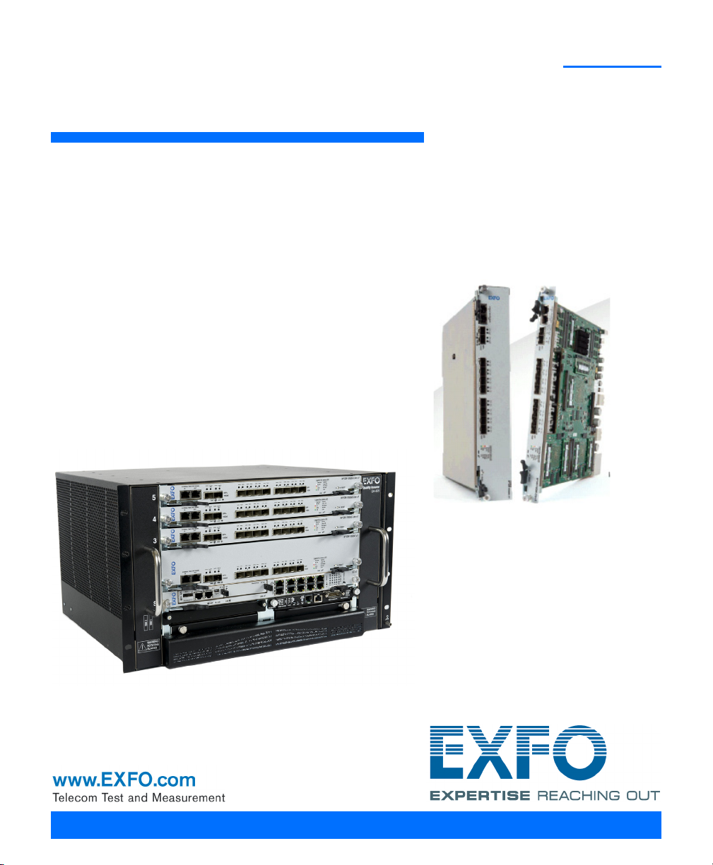
1Introduction
EXFO’s QualityAssurer™ QA-805 is targeted at NEMs and NSPs that are
developing and deploying IMS and wireless networks. The QA-805 offers
easy-to-use test solutions covering the complete testing life cycle of LTE,
IMS, VoLT E, an d Vo IP net wo rk s an d s er vic es .
QA-805 Features
Six-unit rack-mounted
Emulation of over 5 million LTE or IMS subscribers
8 million data sessions
1.25 million RTP streams
50 Gbit/s of user-plane data generation and analysis
USB, DP, Ethernet (management)
QualityAssurer 805 1
Page 10
Introduction
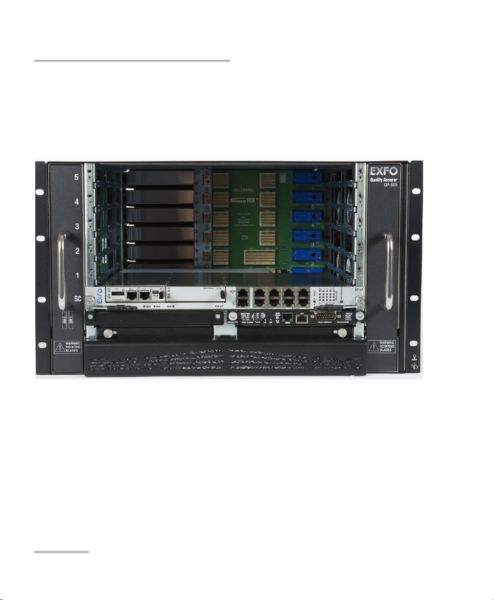
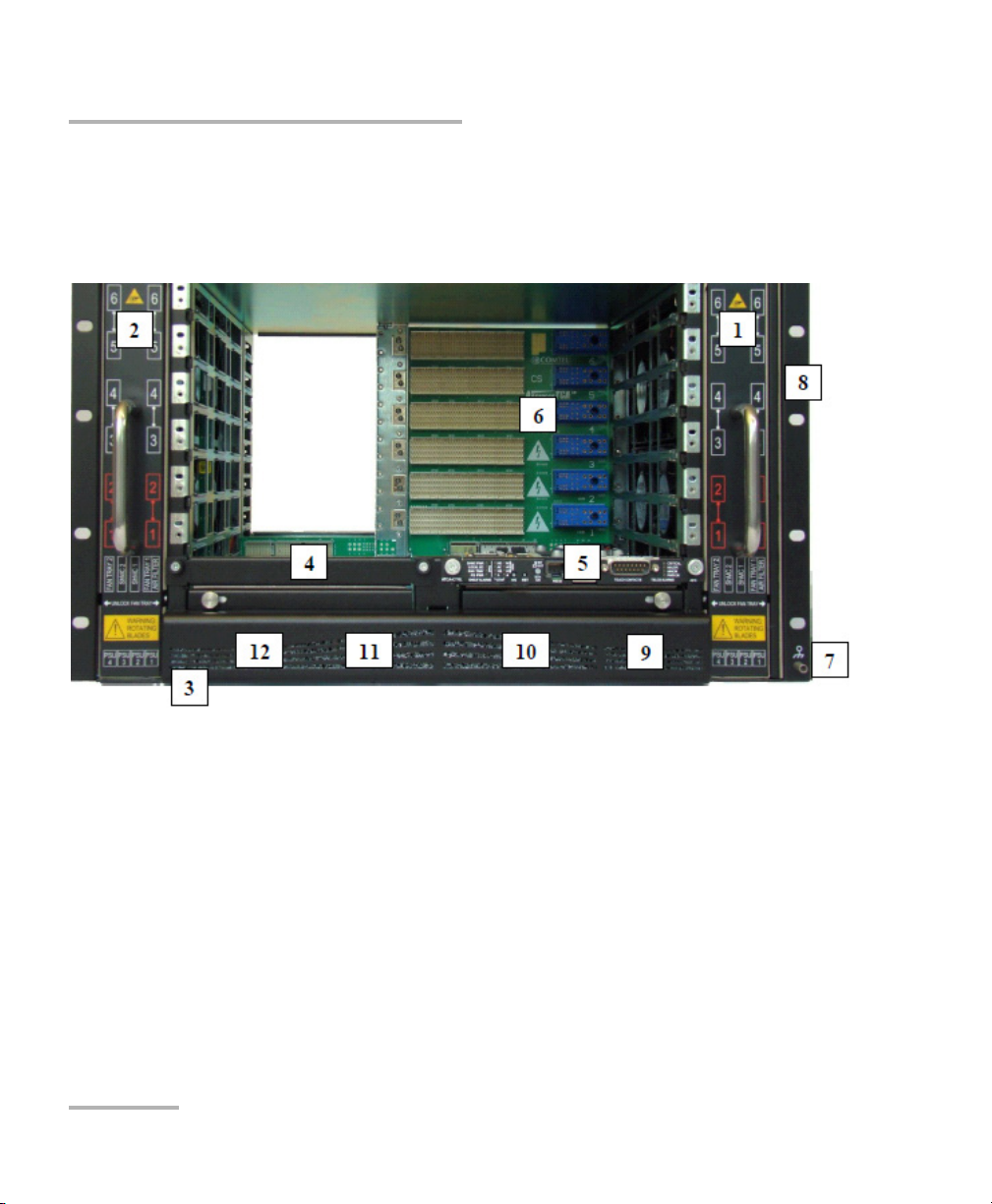
Front View of QA-805
Front View of QA-805
This image of the QA-805 chassis provides a realistic view of the front
panel. See the section Chassis Front Panel on page 4, for further details
that identify specific parts of the QA-805.
2 QA-805 and W2CM Interface Module
Page 11
Introduction
Rear View of QA-805
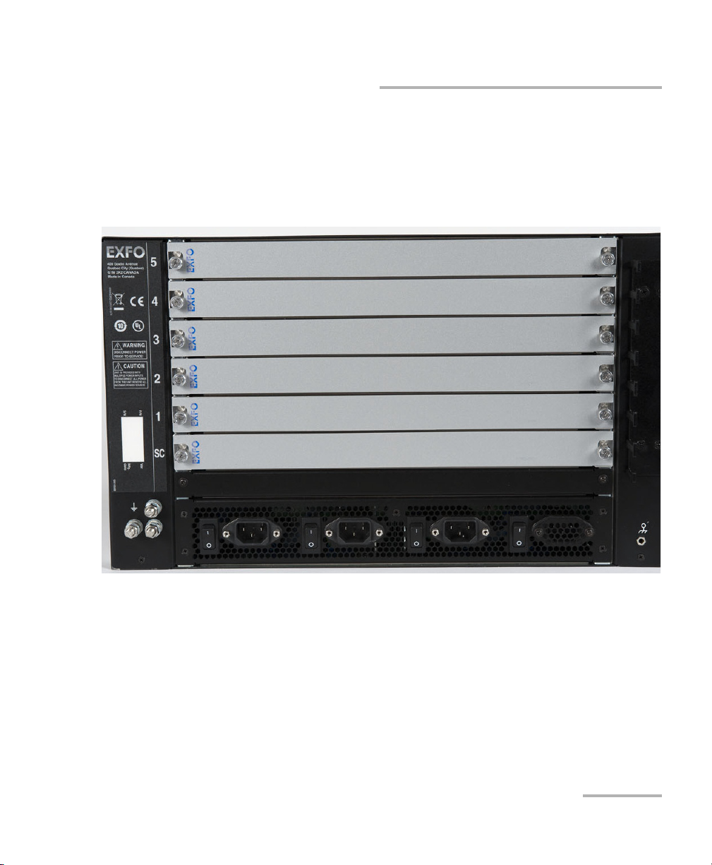
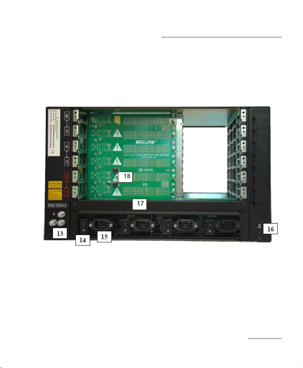
Rear View of QA-805
This image of the rear panel on the QA-805 provides a realistic view of the
back of the chassis. See the section Chassis Back Panel on page 5 for
details of the QA-805 rear panel.
QualityAssurer 805 3
Page 12
Introduction
Physical Description of QA-805 Unit
Physical Description of QA-805 Unit
Chassis Front Panel
The following is a picture of the front of the QA-805 rack-mount model.
1. Right Fan Tray [FT1]
2. Left Fan Tray [FT2]
3. Power supplies cover and air filter holder
4. Control Board/Slot 2 [SHMC2] (not populated)
5. Control Board/Slot 1 [SHMC1] (Shelf Manager)
6. Backplane
7. ESD (Electrostatic Discharge) Wrist Strap Terminal (Banana Jack)
8. Rack ears for mounting in 19” rack
9. Power supply unit/slot 1
4 QA-805 and W2CM Interface Module
Page 13
Physical Description of QA-805 Unit
10. Power supply unit/slot 2
11. Power supply unit/slot 3
12. Power supply unit/slot 4
Chassis Back Panel
The following is a picture of the back of the QA-805 chassis.
Introduction
13. Shelf Ground Terminals
14. Individual Power Switch for each power supply
15. Individual AC Inlet for each power supply
16. ESD Wrist Strap Terminal (Banana Jack)
17. Power Bridge slot
18. Shelf FRU (field replacement unit)
QualityAssurer 805 5
Page 14
Introduction
Physical Description of QA-805 Unit
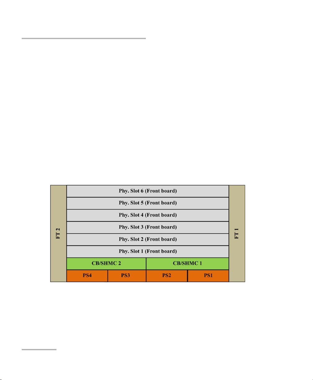
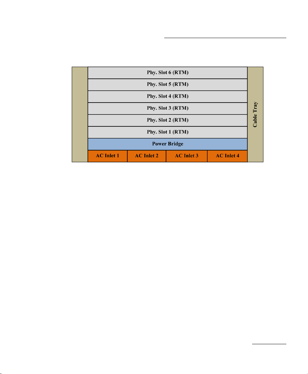
Backplane
The QA-805 provides a monolithic backplane. Power and high speed links
are routed on the same stack up. The backplane supports the following:
6 AdvancedTCA front board slots
6 AdvancedTCA RTM (Rear Transmission Module) slots
2 fan trays
4 power supply slots
Physical Layout
The physical layout of FRUs (field replacement units) populated in the shelf
is shown below.
Front FRU Physical Layout
6 QA-805 and W2CM Interface Module
Page 15
Introduction
Physical Description of QA-805 Unit
Rear FRU Physical Layout
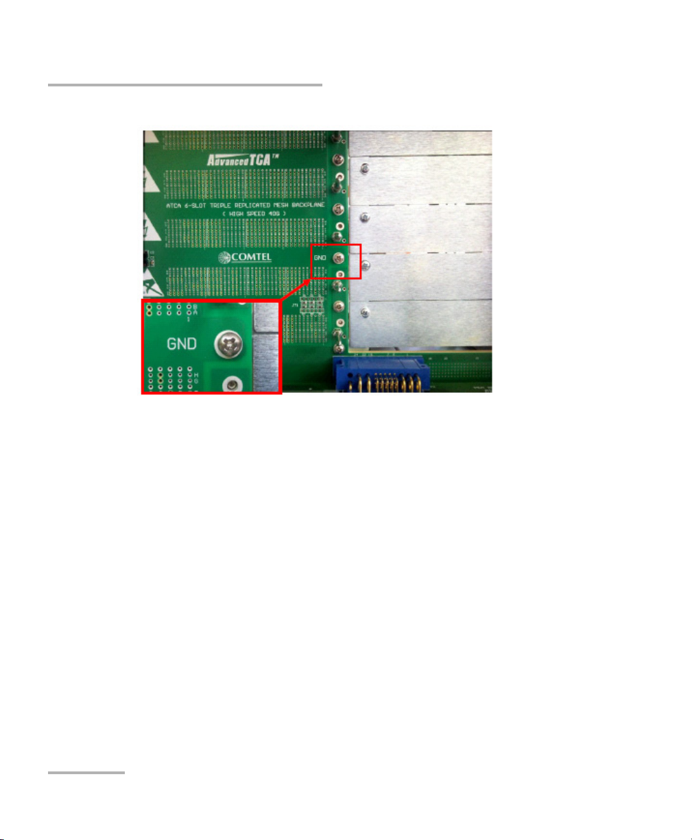
Logic Ground
Logic ground is used as reference for low voltage electronics and is
isolated from the chassis/shelf ground and 48 V power lines. For EMI/EMC
purposes, it might be needed to connect the logic ground and shelf ground
together.
To connect both grounds, a screw with a conductive metal washer is
installed in this location (GND) as shown in the following picture. To
disconnect, remove this screw.
QualityAssurer 805 7
Page 16
Introduction
Physical Description of QA-805 Unit
Note: The screw is installed by default.
8 QA-805 and W2CM Interface Module
Page 17

Introduction
Cooling Assembly
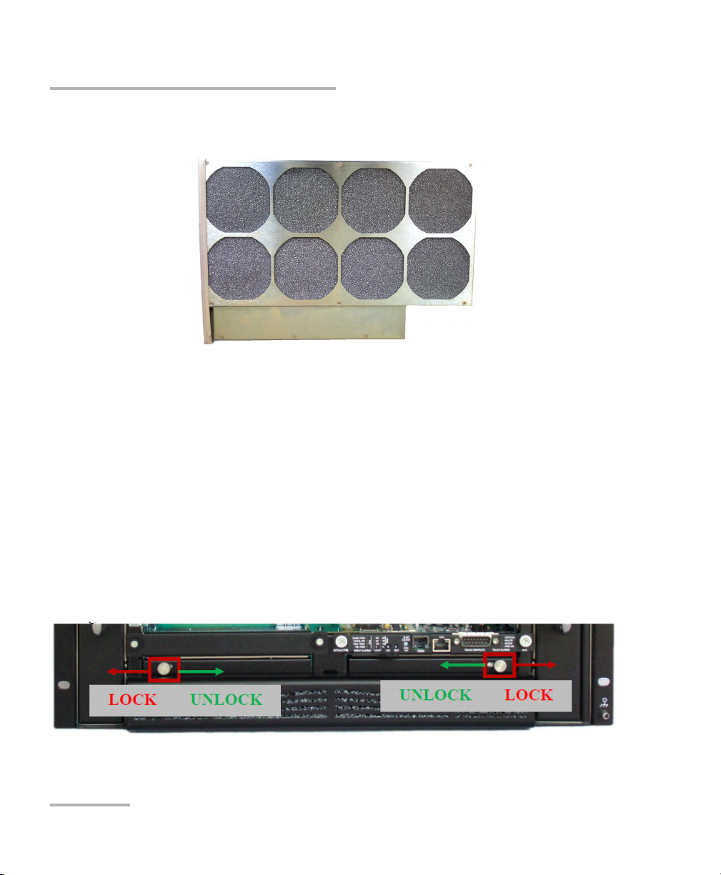
Cooling Assembly
Fan Tray
There are 2 fan tray cassettes in the system. The cooling is performed side
to side. While the fan tray is a single mechanical block, it has 2 functions:
front board cooling and RTM cooling. The front and rear blanks are
necessary for proper airflow.
The fan tray contains electronics such that it is detected as a fully PICMG
compliant IPMC by the shelf manager. It contains hot-swap circuitry,
common fusing, fan supervising, and control circuitry.
The system utilizes push pull cooling with 2 separately managed fan trays
and 4 independent cooling zones. Integrated power supplies enable using
48 V fans without any degradation in performance under 90 – 264 V.
Under normal operating conditions the shelf manager cooling algorithm
sets the fan speed to an acceptable level.
The cooling algorithm works based on temperature events coming from
FRUs. Fan speed in a particular cooling zone will be increased if any FRU in
that zone reports a temperature crossing non-critical threshold. For safety
reasons, if any FRU reports a temperature crossing critical threshold, the
fan speed in all cooling zones will be increased.
QualityAssurer 805 9
Page 18
Introduction
Cooling Assembly
The following depicts the fan tray with air filter frame:
To remove the fan tray:
1. Loosen the locking mechanism and move the head to the left or right
2. Hold the head while pulling out the fan tray using the handle.
To insert the fan tray:
1. Loosen the locking mechanism and move the head to the left or right
(away from the fan tray).
(away from the fan tray).
2. Hold the head while inserting the fan tray using the handle.
3. Tighten the locking mechanism.
The following depicts the fan tray locking mechanism:
10 QA-805 and W2CM Interface Module
Page 19

Introduction
Cooling Assembly
CAUTION
Rotating fan blades can cause injury or cut. Keep hands clear when
servicing. Allow time for fan blades to slow to a stop before fully
removing.
CAUTION
Electrostatic Discharge (ESD) Sensitive Equipment:
To avoid damage due to electrostatic discharge, all removable cards
must be stored and handled using approved ESD protective
packaging. When removing and installing cards use a grounding
wrist strap and work in an approved ESD safe work area.
A GND connection point is located on the front of the chassis.
QualityAssurer 805 11
Page 20

Introduction
Cooling Assembly
Air Filter
The air filter provides:
Filtration of intake air from dust particles
Additional static pressure to achieve uniform airflow
Air filter frame is mounted on the right fan tray cassette.
To change the air filter:
1. Extract the fan tray (FT1, right side looking from front).
2. Replace only the filter material.
3. Re-use the filter frame.
12 QA-805 and W2CM Interface Module
Page 21

Introduction
Power Supplies
Power Supplies
Up to 4 AC power supplies can be plugged in the shelf. The Blutek
BPA-R850-480A power supply is shown below and features the following:
Total output power 850 W-48 VDC output under 90-264 V input
AC frequency range 47-63 Hz
EMI filter EN55022 Class B, FCC Part 15
Active PFC = 0.99
Hot-swappable
Power supply present and power OK sensors
Bi-colour LED indicates Power OK
CAUTION
Internal fusing: Input voltage to this unit is classified as hazardous
connection.
CAUTION
This unit contains electronic components that are sensitive to static
electricity. All electronic boards in this shelf are protected by Shelf
Ground. It is recommended that anti static wrist straps be worn and
connected to a known good shelf ground connection when
servicing.
QualityAssurer 805 13
Page 22

Introduction
Power Supplies
Powering the Shelf
For each power supply, a separate AC inlet as well as switch is provided.
Use power cords rated for currents which exceed the maximum power
supply current.
CAUTION
When working near the power supply power inlets, the shelf
operating voltage falls into 90 - 264 V range. This voltage is
considered hazardous.
14 QA-805 and W2CM Interface Module
Page 23

Introduction
QA-805 Technical Specifications
QA-805 Technical Specifications
Physical Dimensions
Width: 482.60 mm (19 in)
Height: 265.90 mm (10.47 in)
Depth: 388.45 mm (15.29 in)
Weight: 25.50 kg (56 lbs)
D (cable trays): 466.15 mm (18.35 in)
Power Specification
4 slots for redundant hot-swappable power supplies
850 W/power supply at low line (90 V) and high line (264 V)
2N and N+1 (with additional bridge board) redundancy for full mesh
backplane
N+1 redundancy for dual star backplane
Cooling Capability
Push Pull Cooling Scheme
300 W+/ Front Board
35 W+/ RTM
Shelf Management
Pigeon Point SHMM500 shelf manager
Intelligent Fan Trays (IPMC based)
QualityAssurer 805 15
Page 24

Introduction
Conventions
Conventions
Before using the product described in this guide, you should understand
the following conventions:
WARNING
Indicates a potentially hazardous situation which, if not avoided,
could result in death or serious injury. Do not proceed unless you
understand and meet the required conditions.
CAUTION
Indicates a potentially hazardous situation which, if not avoided,
may result in minor or moderate injury. Do not proceed unless you
understand and meet the required conditions.
CAUTION
Indicates a potentially hazardous situation which, if not avoided,
may result in component damage. Do not proceed unless you
understand and meet the required conditions.
IMPORTANT
Refers to information about this product you should not overlook.
16 QA-805 and W2CM Interface Module
Page 25

2 Safety Information
Laser Safety Warnings
WARNING
Do not install or terminate fibers while a light source is active.
Never look directly into a live fiber and ensure that your eyes are
protected at all times.
WARNING
The use of controls, adjustments and procedures other than those
specified herein may result in exposure to hazardous situations or
impair the protection provided by this unit.
IMPORTANT
When you see the following symbol on your unit , make sure
that you refer to the instructions provided in your user
documentation. Ensure that you understand and meet the required
conditions before using your product.
Your instrument is a Class 1 laser product in compliance with standards
IEC 60825-1 2007 and 21 CFR 1040.10. Laser radiation may be encountered
at the output port.
The following label indicates that a product contains a Class 1 source:
QualityAssurer 805 17
Page 26

Safety Information
Operating Cautions
Use only EXFO-supplied or approved Class 1 SFP, SFP+, or XFP
optical transceivers.
Operating Cautions
Rotating fan blades can cause injury or cut. Keep hands clear when
servicing. Allow time for fan blades to slow to a stop before fully
removing.
CAUTION
CAUTION
CAUTION
Electrostatic Discharge (ESD) Sensitive Equipment:
To avoid damage due to electrostatic discharge, all removable cards
must be stored and handled using approved ESD protective
packaging. When removing and installing cards use a grounding
wrist strap and work in an approved ESD safe work area.
A GND connection point is located on the front of the chassis.
18 QA-805 and W2CM Interface Module
Page 27

Safety Information
Installation Instruction Warnings
Installation Instruction Warnings
Rack Mounting
If rack mounted units are installed in a closed or multi-unit rack assembly,
they may require further evaluation by Certification Agencies. The
following items must be considered:
1. The ambient temperature within the rack may be greater than room
temperature. Installation should be such that the amount of air flow
required for safe operation is not compromised. The maximum
temperature for the equipment in this environment is 40 ºC.
Consideration should be given to the maximum rated ambient.
2. Installation should be such that a hazardous stability condition is not
achieved due to uneven loading.
3. Reliable earthing of rack-mounted equipment should be maintained.
4. Thumbscrews should be tightened with a tool after both initial
installation and subsequent access.
CAUTION
Do not lift the chassis by the fan tray handle.
Input Supply
Check nameplate ratings to assure there is no overloading of supply
circuits that could have an effect on overcurrent protection and supply
wiring.
Unit is provided with multiple power inputs. To disconnect all from the
unit remove all incoming power sources.
QualityAssurer 805 19
Page 28

Safety Information
Installation Instruction Warnings
Card Installation
Cards installed in the QA-805 unit are hot-swap tolerant but should only be
hot-swapped when not in use by an application.
Cooling
To ensure optimum cooling within the chassis, all empty slots in the
chassis (front and back) must be filled with the appropriate sized Filler
Panel/Air Baffle.
Ensure that cards are plugged in parallel to the slot. Applying
downward force may result in damage to cards.
CAUTION
20 QA-805 and W2CM Interface Module
Page 29

Equipment Ratings
Tem pe ra tu re
Operation
Storage
Relative humidity
Safety Information
Equipment Ratings
Equipment Ratings
0 °C to 40 °C (32 °F to 104 °F)
–40 °C to 70 °C (–40 °F to 158 °F)
a
95 % non-condensing
Maximum operation
2000 m (6562 ft)
altitude
Pollution degree 2
Overvoltage category II
Input power
unit
each power cord
a. Measured in 0 °C to 31 °C (32 °F to 87.8 °F) range, decreasing linearly to 50 % at 40 °C (104 °F).
b. Not exceeding –10 % to 6 % of the nominal voltage.
b
850 W
100 - 240 V; 50/60 Hz; 11/5 A
QualityAssurer 805 21
Page 30

Page 31

3 Getting Started
AM4020M's HotSwap Switch
Hard Drive's HotSwap Switch
Shelf Installation
CAUTION
Improper installation might cause system damage or personal injury.
Consider the following guidelines:
1. Install the system only in an area with restricted access.
2. Follow the installation rules governed in your country.
3. Power distribution to the shelf must include over current protection
devices.
4. Use appropriate protective bonding conductor according to over
current limits for power lines.
5. Make sure that personnel will not interfere with cables and cords
connected to the rack/shelf.
6. Make sure that the ventilation openings are not disturbed by cables and
rack construction, to allow proper shelf airflow. Otherwise, it may lead
to system damage.
Turning the Unit On/Off
QualityAssurer 805 23
Page 32

Getting Started
Turning the Unit On/Off
Turning Off the Unit
To safely turn off the QA-805, please ensure the following steps
are taken:
1. Stop all test applications and save results to prevent measurement loss.
2. Power down the Processor v1(AM4020M System Controller) by pulling
out the HotSwap switch to its first click position. Wait until the Blue
HotSwap LED stops flashing and turns Solid Blue to indicate that the
System Controller has shut down safely.
3. Power down the Hard Drive(AM4500) by pulling out the HotSwap
switch. Wait until the Blue HotSwap LED stops flashing and turns Solid
Blue to indicate that the Hard Drive has shut down safely.
4. Power down all active power supplies.
Turning On the Unit
To safely turn on the QA-805, please ensure the following steps
are taken:
1. Ensure that all empty slots are filled with the appropriate sized Filler
Card/Air Baffle.
2. Ensure that the HotSwap switches on both the Processor v1(AM4020M
System Controller) and Hard Drive(AM4500) are fully pushed in.
3. Power up all required power supplies.
24 QA-805 and W2CM Interface Module
Page 33

4W2CM-10Gb Ethernet Interface
Series
The W2CM-10GbE module tests fixed-mobile converged networks and
services like wireless (2G/3G/LTE), IMS, VoLTE, and VoIP. It is specially
designed for signaling and user-plane testing of network elements such as
the P-GW, S-GW, eNodeB, SBC, CSCFs, BGF, HSS, and IMS application
servers.
With EXFO’s QA-805, the W
2
W
CM-4GbE modules can emulate tens of millions of subscribers,
generating real-world traffic toward LTE, IMS, and VoIP networks.
Note: The W
hardware, but extra capacity can be enabled through the purchase of an
upgrade licence. Please see Contacting the Technical Support Group on
page 37 to contact EXFO.
W2CM-10GbE 2-slot module
2
CM-10GbE Lite and W2CM-4GbE options use the same physical
2
CM-10GbE, W2CM-10GbE Lite, and
QualityAssurer 805 25
Page 34

W2CM-10Gb Ethernet Interface Series
Module Installation
W2CM-10GbE Lite/W2CM-4GbE 1-slot module
Module Installation
The W2CM modules are hot-swappable, but care must be taken when and
how the modules are removed.
Inserting a Module
Follow these steps to insert a module into the QA-805 Chassis:
1. Remove any Filler Cards/Air Baffles required, to provide space for the
module being inserted.
2. Before inserting the card, ensure that the levers on either side of the
card are in the fully open position, perpendicular to the faceplate.
3. Align the card with the card rails and gently glide the card straight into
the chassis. Ensure that the guide-pins insert into their associated holes
in the chassis.
4. Ensure that no cables are between the card's faceplate and the chassis.
5. To fully seat the card into the chassis, use constant pressure while
closing both levers, allowing the levers to pull the card into position.
26 QA-805 and W2CM Interface Module
Page 35

W2CM-10Gb Ethernet Interface Series
Module Installation
6. Ensure levers fully lock into the closed position. If the chassis is
powered up, the Blue HotSwap LED flashes briefly and then turns off.
7. Secure the module to the chassis with the screws on either side of the
module.
8. If required, connect the External Time Sync cables to the card to
provide the synchronized hardware based timestamps for test
measurements.
9. Re-insert any cables into the test-port as required.
Extracting a Module
Follow these steps to remove a module from the QA-805 Chassis:
1. If the chassis is powered up, ensure that the module is not in use in any
Test Application, otherwise measurement data could be lost.
2. Fully loosen the screws on either side of the module.
3. Remove any cables connected to the module, noting their positions if
needed.
4. If the External Time Sync cables are plugged into this card, move them
to another card in the system to ensure the chassis will still have a
synchronized hardware based timestamp.
5. If the chassis is powered up, release the HotSwap latches to start the
HotSwap process. The Blue HotSwap LED will blink for several
seconds. When the LED is solid blue, the card can be safely extracted.
6. Slowly open both levers, applying constant pressure to unseat the card
from the chassis's backplane.
7. Slide the module carefully out of the chassis along the guide rails.
8. Fill any open slots in the chassis with an appropriate
Filler Card/Air Baffle.
QualityAssurer 805 27
Page 36

W2CM-10Gb Ethernet Interface Series
10/100/1000 M Copper and 1 G Optical Interfaces (SFP)
10/100/1000 M Copper and 1 G Optical
Interfaces (SFP)
Eight SFP interfaces are available on the faceplate for either optical or
copper plugable SFPs. Neither copper nor optical SFPs have built-in LEDs
consequently two LEDs per SFP are positioned right beside each SFP cage.
LED definition for 10/100/1000 M copper SFP:
LED# Label Color Definition
1 Activity Off Idle
Green Unidirectional Activity RX
Yellow Bidirectional Activity
Red Unidirectional Activity TX
LED# Label Color Definition
2 Link/Speed Off No link
Green 10 Mbps
Yellow 100 Mbps
Red 1 Gbps
28 QA-805 and W2CM Interface Module
Page 37

W2CM-10Gb Ethernet Interface Series
10/100/1000 M Copper and 1 G Optical Interfaces (SFP)
LED definition for 1 G optical SFP:
LED# Label Color Definition
1 Activity Off Idle
Green Unidirectional Activity RX
Yellow Bidirectional Activity
Red Unidirectional Activity TX
LED# Label Color Definition
2 Laser On/Signal Off Laser off
Green Laser on - signal, with link
Yellow Laser on - signal, no link
Red Laser on - no signal
10/100/1000 M Copper SFP
The component for the copper SFP is the
Finisar FCLF8520P2BTL which supports a
10/100/1000BASE-T operation, and
integrates a Marvell's PHY 88E1111. The
FCLF8520P2BTL uses the SFP's RX_LOS
pin for link indication while 1000BASE-X
auto-negotiation should be disabled on
the host system.
QualityAssurer 805 29
Page 38

W2CM-10Gb Ethernet Interface Series
10/100/1000 M Copper and 1 G Optical Interfaces (SFP)
1 G Optical SFP
The following optical Class 1 Laser SFPs from Finisar are
supported:
EXFO
Product #
Transceivers
(Finisar)
FTB-8590 FTLF8519P2BNL
1000BASE-SX
Multi-rate:
GigE, 1xFC, 2xFC
FTB-8591 FTRJ1319P1BTL
1000BASE-LX
Multi-rate:
GigE, 1xFC, 2xFC
FTB-8592 FTRJ1519P1BCL
1000BASE-ZX
Multi-rate:
GigE, 1xFC, 2xFC
Optical SFP with LC connector
Output
Power
(dBm)
MIN = -9
MAX= -3
MIN = -9.5
MAX = -3
MIN = 0
MAX = +5
Rx Sensitivity
(dBm)
(@ GigE)
MIN = n/a
MAX = -20
(@ GigE)
MIN = n/a
MAX = -22
(@ GigE)
MIN = n/a
MAX = -22
SFP Specs
850 nm
SR /500 m
1310 nm
IR1 /10 km
1550 nm
LR2 /90 km
30 QA-805 and W2CM Interface Module
Page 39

W2CM-10Gb Ethernet Interface Series
10 G LAN/WAN Optical Interfaces (SFP+)
10 G LAN/WAN Optical Interfaces (SFP+)
Two Class 1 Laser SFP+ interfaces are available on the faceplate. On the
host side, these SFP+ interfaces are connected directly to the LIM FPGA.
The following optical SFP+ from Finisar, are supported:
EXFO
Product #
FTB-8690 FTLX8571D3BCL
Transceivers
(Finisar)
Multi-rate
MIN = -5
MAX = -1
9.95-10.3 Gbit/s
10GBASE-SR/SW
FTB-8691 FTLX1471D3BCL
Multi-rate
MIN = -8.2
MAX=+0.5
9.95-10.5 Gbit/s
10GBASE-LR/LW
10GFC
FTB-8692 FTLX1671D3BCL
Multi-rate
MIN = -4.7
MAX =+4.0
9.95-10.3 Gbit/s
10GBASE-ER/EW
Optical SFP+ with LC Connector
Output
Power
(dBm)
Rx Sensitivity
(dBm)
@ 10.3 Gbit/s
MIN = -11.1
MAX = 0.5
@ 10.3 Gbit/s
MIN = -12.6
MAX= 0.5
@ 10 Gbit/s
MIN = -14.1
MAX = -1.0
SFP+ Specs
850 nm
300 m OM3
1310 nm
10 km SMF
1550 nm
40 km SMF
QualityAssurer 805 31
Page 40

W2CM-10Gb Ethernet Interface Series
10 G LAN/WAN Optical Interfaces (SFP+)
LED definition for 10 G optical SFP+:
LED# Label Color Definition
1 Activity Off Idle
LED# Label Color Definition
2 Laser On/Signal Off Laser off
Green Unidirectional Activity RX
Yellow Bidirectional Activity
Red Unidirectional Activity TX
Green Laser on - signal, with link
Yellow Laser on - signal, no link
Red Laser on - no signal
32 QA-805 and W2CM Interface Module
Page 41

5 Maintenance
To help ensure long, trouble-free operation:
Always inspect fiber-optic connectors before using them and clean
them if necessary.
Keep the unit free of dust.
Clean the unit casing and front panel with a cloth slightly dampened
with water.
Store unit at room temperature in a clean and dry area. Keep the unit
out of direct sunlight.
Avoid high humidity or significant temperature fluctuations.
Avoid unnecessary shocks and vibrations.
If any liquids are spilled on or into the unit, turn off the power
immediately, disconnect from any external power source and let the
unit dry completely.
The use of controls, adjustments and procedures other than those
specified herein may result in exposure to hazardous situations or
impair the protection provided by this unit.
WARNING
Maintaining Air Filters
Due to the environment the system operates in, the filters will accumulate
dust, causing a degradation in filtration and airflow to the system.
Therefore the filters must be replaced periodically with the frequency
depending on the environment, for instance, in clean laboratory
environment - one time per half year.
The first air filter is mounted on the right fan tray and intended for filtering
the air used for cooling the ATCA blades. The second air filter is located at
lower front of the shelf and intended for filtering the air used for cooling the
AC power supplies.
QualityAssurer 805 33
Page 42

Maintenance
Fan Tray Replacing
To replace the ATCA card cage air filter, perform the following:
1. Slowly remove the right fan tray.
2. Remove the screws from the filter on the fan tray.
3. Remove the filter from the card cage.
4. Remove the dust from the fan tray with a soft brush.
5. Insert a new filter in the frame and screw it on the fan tray.
6. Insert the fan tray in the system.
To replace the AC power supplies filter, perform the following:
1. Remove the front panel covering the power supply slots.
2. Carefully and slowly remove the old filter.
3. Install a new filter.
4. Replace the front panel.
The old air filter can be cleaned with a vacuum cleaner but this is not
recommended since the filter will never regain its original properties after
cleaning.
Fan Tray Replacing
Fan trays should be replaced due to wear and tear. The malfunction of a
fan tray will be reported via the shelf manager (fan tachometer sensors). In
case of failure, immediately replace the faulty fan tray, otherwise the
degradation in cooling performance may cause overheating of the ATCA
blades. For further details, see Fan Tray on page 9.
Power Supply Replacing
A power supply should be replaced in case of failure. The malfunction of
the power supply will be reported via the shelf manager (Power OK
sensor), the red LED at the front of power supply and additionally via the
front panel LED.
34 QA-805 and W2CM Interface Module
Page 43

Maintenance
Recycling and Disposal (Applies to European Union Only)
Recycling and Disposal
(Applies to European Union Only)
For complete recycling/disposal information as per European Directive
WEEE 2012/19/UE, visit the EXFO Web site at www.exfo.com/recycle.
QualityAssurer 805 35
Page 44

Page 45

6 Troubleshooting
Contacting the Technical Support Group
To obtain after-sales service or technical support for this product, contact
local EXFO Navtel Product Group representative at one of the following
numbers.
For detailed information about technical support, visit the EXFO Web site at
www.exfo.com.
Technical Support Group
160 Drumlin Circle
Concord, ON L4K 3E5
CANADA
For detailed information about technical support, and for a list of other
worldwide locations, visit the EXFO Web site at www.exfo.com.
To accelerate the process, please have information such as the name and
the serial number (see the product identification label), as well as a
description of your problem, close at hand.
1 800 267-7235 (USA and Canada)
Tel.: 1 905 738-3741
Email: info@exfo.com
QualityAssurer 805 37
Page 46

Troubleshooting
Transportation
Transportation
Maintain a temperature range within specifications when transporting the
unit. Transportation damage can occur from improper handling. The
following steps are recommended to minimize the possibility of damage:
Pack the unit in its original packing material when shipping.
Ensure all cards are secured with the screws provided.
Avoid high humidity or large temperature fluctuations.
Keep the unit out of direct sunlight.
Avoid unnecessary shocks and vibrations.
38 QA-805 and W2CM Interface Module
Page 47

7 Warranty
General Information
EXFO Inc. (EXFO) warrants this equipment against defects in material and
workmanship for a period of XX Number of Years XX from the date of
original shipment. EXFO also warrants that this equipment will meet
applicable specifications under normal use.
During the warranty period, EXFO will, at its discretion, repair, replace,
or issue credit for any defective product, as well as verify and adjust the
product free of charge should the equipment need to be repaired or if the
original calibration is erroneous. If the equipment is sent back for
verification of calibration during the warranty period and found to meet all
published specifications, EXFO will charge standard calibration fees.
The warranty can become null and void if:
unit has been tampered with, repaired, or worked upon by
unauthorized individuals or non-EXFO personnel.
IMPORTANT
warranty sticker has been removed.
case screws, other than those specified in this guide, have been
removed.
case has been opened, other than as explained in this guide.
unit serial number has been altered, erased, or removed.
unit has been misused, neglected, or damaged by accident.
THIS WARRANTY IS IN LIEU OF ALL OTHER WARRANTIES EXPRESSED,
IMPLIED, OR STATUTORY, INCLUDING, BUT NOT LIMITED TO, THE
IMPLIED WARRANTIES OF MERCHANTABILITY AND FITNESS FOR A
PARTICULAR PURPOSE. IN NO EVENT SHALL EXFO BE LIABLE FOR
SPECIAL, INCIDENTAL, OR CONSEQUENTIAL DAMAGES.
QualityAssurer 805 39
Page 48

Warranty
Liability
Liability
EXFO shall not be liable for damages resulting from the use of the product,
nor shall be responsible for any failure in the performance of other items to
which the product is connected or the operation of any system of which
the product may be a part.
EXFO shall not be liable for damages resulting from improper usage or
unauthorized modification of the product, its accompanying accessories
and software.
40 QA-805 and W2CM Interface Module
Page 49

Warranty
Exclusions
EXFO reserves the right to make changes in the design or construction of
any of its products at any time without incurring obligation to make any
changes whatsoever on units purchased. Accessories, including but not
limited to fuses, pilot lamps, batteries and universal interfaces (EUI) used
with EXFO products are not covered by this warranty.
This warranty excludes failure resulting from: improper use or installation,
normal wear and tear, accident, abuse, neglect, fire, water, lightning or
other acts of nature, causes external to the product or other factors beyond
the control of EXFO.
IMPORTANT
In the case of products equipped with optical connectors, EXFO will
charge a fee for replacing connectors that were damaged due to
misuse or bad cleaning.
Certification
Exclusions
EXFO certifies that this equipment met its published specifications at the
time of shipment from the factory.
QualityAssurer 805 41
Page 50

Warranty
Service and Repairs
Service and Repairs
EXFO commits to providing product service and repair for five years
following the date of purchase.
To send any equipment for service or repair:
1. Call one of EXFO’s authorized service centers (see EXFO Service
2. If equipment must be returned to EXFO or an authorized service
3. If possible, back up your data before sending the unit for repair.
4. Pack the equipment in its original shipping material. Be sure to include
5. Return the equipment, prepaid, to the address given to you by support
Centers Worldwide on page 43). Support personnel will determine if
the equipment requires service, repair, or calibration.
center, support personnel will issue a Return Merchandise
Authorization (RMA) number and provide an address for return.
a statement or report fully detailing the defect and the conditions under
which it was observed.
personnel. Be sure to write the RMA number on the shipping slip. EXFO
will refuse and return any package that does not bear an RMA number.
Note: A test setup fee will apply to any returned unit that, after test, is found to
meet the applicable specifications.
After repair, the equipment will be returned with a repair report. If the
equipment is not under warranty, you will be invoiced for the cost
appearing on this report. EXFO will pay return-to-customer shipping costs
for equipment under warranty. Shipping insurance is at your expense.
Routine recalibration is not included in any of the warranty plans. Since
calibrations/verifications are not covered by the basic or extended
warranties, you may elect to purchase FlexCare Calibration/Verification
Packages for a definite period of time. Contact an authorized service center
(see EXFO Service Centers Worldwide on page 43).
42 QA-805 and W2CM Interface Module
Page 51

Warranty
EXFO Service Centers Worldwide
EXFO Service Centers Worldwide
If your product requires servicing, contact your nearest authorized service
center.
EXFO Headquarters Service Center
400 Godin Avenue
Quebec (Quebec) G1M 2K2
CANADA
EXFO Europe Service Center
Winchester House, School Lane
Chandlers Ford, Hampshire S053 4DG
ENGLAND
EXFO Telecom Equipment
(Shenzhen) Ltd.
3rd Floor, Building 10,
Yu Sheng Industrial Park (Gu Shu
Crossing), No. 467,
National Highway 107,
Xixiang, Bao An District,
Shenzhen, China, 518126
1 866 683-0155 (USA and Canada)
Tel.: 1 418 683-5498
Fax: 1 418 683-9224
support@exfo.com
Tel.: +44 2380 246800
Fax: +44 2380 246801
support.europe@exfo.com
Tel: +86 (755) 2955 3100
Fax: +86 (755) 2955 3101
support.asia@exfo.com
QualityAssurer 805 43
Page 52

Page 53

A Technical Specifications
SPECIFICATIONS
QA-813 QA-805 QA-604
Platform 13 slots, rack-mounted 5 slots, rack-mounted 4 slots, rack-mounted or desktop
Hot-swappable modules Up to 6 W
2
CM-10GbE or
13 W
2
CM-10GbE-Lite
Up to 2 W
2
CM-10GbE or
5 W
2
CM-10GbE-Lite
Up to 4 SCM-GbE or 2 MCM-GbE
(or MCM-GbE-Lite)
Reset Per platform, per interface or per port
(hardware or software)
Per platform, per interface or per port
(hardware or software)
Per platform, per interface or per port
(hardware or software)
Interfaces USB, DP, Ethernet (management) USB, DP, Ethernet (management) USB (2), VGA, Ethernet (management)
Operating system Linux Linux Solaris
Processor and memories AMC Core i7 2.53 GHz, 8 GB RAM,
500 GB hard disk
AMC Core i7 2.53 GHz, 8 GB RAM,
500 GB hard disk
Intel Core 2 Duo, 2 GHz, 2 GB RAM (min),
120 GB hard disk (min)
Remote control Standard Windows applications
such as VNC and Exceed
Standard Windows applications
such as VNC and Exceed
Standard Windows applications
such as VNC and Exceed
Size (H x W x D)
577 mm x 443 mm x 434 mm
(22.72 in x 17.44 in x 17.09 in)
265.90 mm x 482.60 mm x 388.45 mm
(10.47 in x 19 in x 15.29 in)
101 mm x 483 mm x 362 mm
(4 in x 19 in x 14 ¼ in)
Weight 29 kg (64 lb) 25.50 kg (56 lb) 5.5 kg (12.1 lb)
Power supply Recommended rectifier:
Input: 90-277 V, 47-63 Hz, 25 A x 4
Output: 60 V — Max. 17200 W
850 W, 90 to 264 V input,
single plus 5 VSB output
100 to 240 V, 50/60 H
IMPORTANT
The following technical specifications can change without notice.
The information presented in this section is provided as a reference
only. To obtain this product’s most recent technical specifications,
visit the EXFO Web site at www.exfo.com.
QualityAssurer - QA-805
QualityAssurer 805 45
Page 54

Technical Specifications
Test s
n
d
H
S
S
C
AMR,
S
2
(W
C
)
e
2
W
C
)
T
t
2
(W
C
)
p
5
(W
C
)
C
A
s
s
8
H
s
Hard
ce
)
d
Q
)
Q
)
A
t
e
1
8
1
8
1
W2CM 10 Gigabit Ethernet Interface Series
W2CM 10 Gigabit Ethernet Interface Series
olutio
Protocol supporte
ODEC support
IP/LTE endpoints per module
Number of sessions per modul
hroughpu
Number of RTP streams
er module
onnection speed
Number of port
ot-swappable modules Ye
ware varian
Platforms supporte
vailable SFP
ransceiver modul
LTE eNodeB, P-GW, S-GW, MME
SBC, security gateways, BGF, IMS I/P/C-CSCF, HSS, SIP proxy/registrar
TTP, SMTP,POP,RTSP, GTP-c, GTP-u, S1-AP, S1-MME, NAS, SIP, Diameter, Megaco/H.248, RTP/RTCP,
RTP/SRTCP, TLS, IPSec, IKEv1, IKEv2, IPv4, IPv6, TCP, UDP, SCTP, DHCP, DN
ILBC, G.711, G.729, G.721, G.722, G.726, G.723, G.728, EVRC, EVRC-B, GSM-EFR, GSM-FR, GSM-HR, H.263, H.264, DTMF
million (WCM-10GbE), 1 million
million (WCM-10GbE), 1 million (
2
0 Gbit/s
12 000
uto-negotiate 10/100/1000/10000 Mbit/
x 1GbE and 2 x 10GbE
A-805 (2xW2CM-10GbE or 5xW2CM-10GbE-Lite
A-813 (6xW2CM-10GbE or 13xW2CM-10GbE-Lite
000Base-T SFP
50 nm, 500 m SFP
310 nm, 10 km SFP
50 nm, 300 m SFP+
310 nm, 10 km SFP+
M-10GbE), 10 Gbit/s (W2CM-10GbE-Lite
2
M-10GbE), 256 000 (W
CM-10GbE (2 slots module), W
M-10GbE-Lite
M-10GbE-Lite
CM-10GbE-Lite
CM-10GbE-Lite (1 slot module
46 QA-805 and W2CM Interface Module
Page 55

Index
Index
A
AC requirements ......................................... 21
after-sales service ........................................ 37
C
caution
of personal hazard................................. 16
of product hazard.................................. 16
certification information ................................v
cleaning
front panel............................................. 33
conventions, safety ..................................... 16
current, electrical ........................................ 21
customer service.......................................... 42
E
equipment returns ...................................... 42
F
front panel, cleaning ................................... 33
I
identification label ...................................... 37
input current ............................................... 21
P
power source, AC ........................................ 21
product
identification label ................................. 37
specifications ......................................... 45
R
return merchandise authorization (RMA) .... 42
S
safety
caution................................................... 16
conventions ...........................................16
warning .................................................16
service and repairs....................................... 42
service centers ............................................. 43
shipping to EXFO......................................... 42
specifications, product ................................45
storage requirements ..................................33
symbols, safety ............................................ 16
T
technical specifications................................ 45
technical support......................................... 37
temperature for storage .............................. 33
transportation requirements.................. 33, 38
L
label, identification ..................................... 37
M
maintenance
front panel............................................. 33
general information............................... 33
maximum input current .............................. 21
QualityAssurer 805 47
UL.................................................................. v
Underwriters Laboratories (UL)...................... v
U
Page 56

Index
W
warranty
certification ........................................... 41
exclusions .............................................. 41
general .................................................. 39
liability................................................... 40
null and void.......................................... 39
48 QA-805 and W2CM Interface Module
Page 57

NOTICE
抩⛙
CHINESE REGULATION ON RESTRICTION OF HAZARDOUS SUBSTANCES
₼⦌␂ℝ☀⹂䓸德棟Ⓟ䤓屓⸩
NAMES AND CONTENTS OF THE TOXIC OR HAZARDOUS SUBSTANCES OR ELEMENTS
CONTAINED IN THIS EXFO PRODUCT
▔⚺⦷㦻 EXFO ℶ❐₼䤓㦘㹡㦘⹂䓸德㒥⏒侯䤓⚜䱿✛⚺摞
O
Indicates that this toxic or hazardous substance contained in all of the homogeneous
materials for this part is below the limit requirement in SJ/T11363-2006
嫷䯉年㦘㹡㦘⹂䓸德⦷年捷ↅ㓏㦘⧖德㧟㠨₼䤓⚺摞⧖⦷ SJ/T11363-2006 㪖屓⸩䤓
棟摞尐㻑ⅴₚᇭ
X
Indicates that this toxic or hazardous substance contained in at least one of the homogeneous
materials used for this part is above the limit requirement in SJ/T11363-2006
嫷䯉年㦘㹡㦘⹂䓸德咂⺠⦷年捷ↅ䤓㩟⧖德㧟㠨₼䤓⚺摞怔⒉ SJ/T11363-2006 㪖
屓⸩䤓棟摞尐㻑ᇭ
Part Name
捷ↅ⚜䱿
Toxic or hazardous Substances and Elements
㦘㹡㦘⹂䓸德✛⏒侯
Lead
杔
(Pb)
Mercury
㻭
(Hg)
Cadmium
椣
(Cd)
Hexavalent
Chromium
⏼ↆ杻
(Cr VI)
Pol yb ro mi na ted
biphenyls
⮩䅃勣啾
(PBB)
Polybrominated
diphenyl ethers
⮩䅃ℛ啾搩
(PBDE)
Enclosure
⮥⮂
OO O O O O
Electronic and
electrical
sub-assembly
䟄✛䟄兓ↅ
XO X O X X
Optical
sub-assembly
a
⏘ⷵ兓ↅ
a
a. If applicable.
Ⱁ㨫抑䞷ᇭ
XO O O O O
Mechanical
sub-assembly
a
㧉㬿兓ↅ
a
OO O O O O
MARKING REQUIREMENTS
㪖㽷尐㻑
Product
ℶ❐
Environmental protection use period (years)
䘾⬒≬㔳∎䞷㦮棟 ( )
Logo
㪖㉦
his Exfo product
㦻 EXFO ℶ❐
10
Battery
a
䟄㻯
a
f applicable.
5
NOTICE
抩⛙
CHINESE REGULATION ON RESTRICTION OF HAZARDOUS SUBSTANCES
₼⦌␂ℝ☀⹂䓸德棟Ⓟ䤓屓⸩
NAMES AND CONTENTS OF THE TOXIC OR HAZARDOUS SUBSTANCES OR ELEMENTS
CONTAINED IN THIS EXFO PRODUCT
▔⚺⦷㦻 EXFO ℶ❐₼䤓㦘㹡㦘⹂䓸德㒥⏒侯䤓⚜䱿✛⚺摞
O
Indicates that this toxic or hazardous substance contained in all of the homogeneous
materials for this part is below the limit requirement in SJ/T11363-2006
嫷䯉年㦘㹡㦘⹂䓸德⦷年捷ↅ㓏㦘⧖德㧟㠨₼䤓⚺摞⧖⦷ SJ/T11363-2006 㪖屓⸩䤓
棟摞尐㻑ⅴₚᇭ
X
Indicates that this toxic or hazardous substance contained in at least one of the homogeneous
materials used for this part is above the limit requirement in SJ/T11363-2006
嫷䯉年㦘㹡㦘⹂䓸德咂⺠⦷年捷ↅ䤓㩟⧖德㧟㠨₼䤓⚺摞怔⒉ SJ/T11363-2006 㪖
屓⸩䤓棟摞尐㻑ᇭ
Part Name
捷ↅ⚜䱿
Toxic or hazardous Substances and Elements
㦘㹡㦘⹂䓸德✛⏒侯
Lead
杔
(Pb)
Mercury
㻭
(Hg)
Cadmium
椣
(Cd)
Hexavalent
Chromium
⏼ↆ杻
(Cr VI)
Pol yb ro mi na ted
biphenyls
⮩䅃勣啾
(PBB)
Polybrominated
diphenyl ethers
⮩䅃ℛ啾搩
(PBDE)
Enclosure
⮥⮂
OO O O O O
Electronic and
electrical
sub-assembly
䟄✛䟄兓ↅ
XO X O X X
Optical
sub-assembly
a
⏘ⷵ兓ↅ
a
a. If applicable.
Ⱁ㨫抑䞷ᇭ
XO O O O O
Mechanical
sub-assembly
a
㧉㬿兓ↅ
a
OO O O O O
Page 58

MARKING REQUIREMENTS
㪖㽷尐㻑
Product
ℶ❐
Environmental protection use period (years)
䘾⬒≬㔳∎䞷㦮棟 ( )
Logo
㪖㉦
This Exfo product
㦻 EXFO ℶ❐
10
Battery
a
䟄㻯
a
a. If applicable.
Ⱁ㨫抑䞷ᇭ
5
Page 59

P/N: 1063196
www.EXFO.com · info@exfo.com
CORPORATE HEADQUARTERS 400 Godin Avenue Quebec (Quebec) G1M 2K2 CANADA
Tel.: 1 418 683-0211 · Fax: 1 418 683-2170
EXFO AMERICA 3400 Waterview Parkway Suite 100 Richardson, TX 75080 USA
EXFO EUROPE Winchester House,
EXFO ASIA-PACIFIC 100 Beach Road,
EXFO CHINA Beijing Global Trade Center, Tower C,
EXFO SERVICE ASSURANCE 270 Billerica Road Chelmsford MA, 01824 USA
EXFO FINLAND Elektroniikkatie 2 FI-90590 Oulu, FINLAND
TOLL-FREE (USA and Canada) 1 800 663-3936
© 2013 EXFO Inc. All rights reserved.
Printed in Canada (2013-04)
School Lane
#25-01/03 Shaw Tower
Room 1207, 36 North Third Ring Road
East, Dongcheng District
Tel.: 1 972-761-927 · Fax: 1 972-761-9067
Chandlers Ford, Hampshire S053 4DG ENGLAND
Tel.: +44 2380 246 800 · Fax: +44 2380 246 801
SINGAPORE 189702
Tel.: +6563338241 · Fax: +6563338242
Beijing 100013 P. R. CHINA
Tel.: +86 (10) 5825 7755 · Fax: +86 (10) 5825 7722
Tel.: 1 978 367-5600 · Fax: 1 978 367-5700
Tel.: +358 (0) 403 010 300 · Fax: +358 (0) 8 564 5203
 Loading...