

Page 1
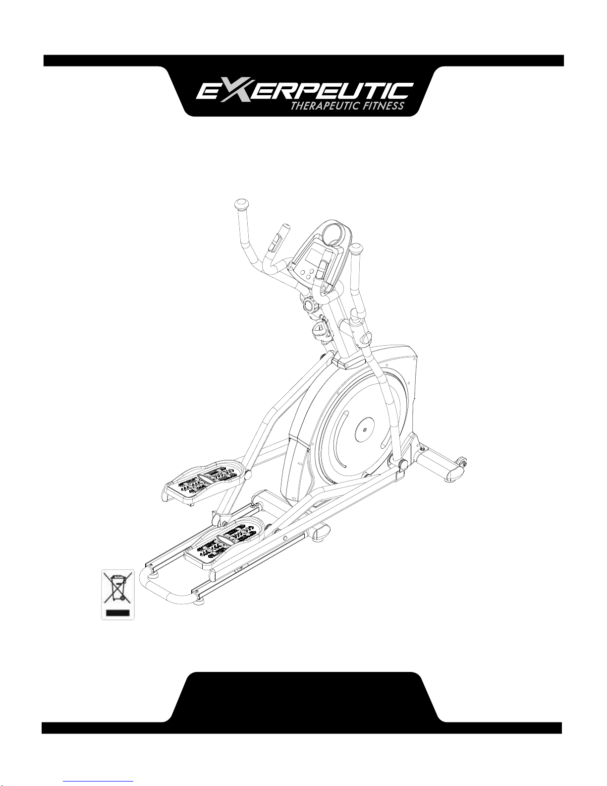
Pro Stride 21 Elliptical
IMPORTANT: Read all instructions carefully before using this product.
Retain this owner’s manual for future reference.
The specifications of this product may vary from this photo, subject to change
without notice.
Item 1304
OWNER’S
Page 2

SERVICE ------------------------------------------------------------------------ 2
IMPORTANT LABELS -------------------------------------------------------- 3
PRODUCT SAFETY ---------------------------------------------------------- 4
PART DRAWING -------------------------------------------------------------- 5
BOX CONTENTS ------------------------------------------------------------- 6
PART LIST ---------------------------------------------------------------------- 8
ASSEMBLY --------------------------------------------------------------------- 10
COMPUTER -------------------------------------------------------------------- 24
ADJUSTMENTS --------------------------------------------------------------- 27
TROUBLE SHOOTING & MAINTENANCE ----------------------------- 28
WARM UP ----------------------------------------------------------------------- 29
WARRANTY -------------------------------------------------------------------- 30
FAX FORM ---------------------------------------------------------------------- 31
TABLE OF
1
Page 3

IMPORTANT: FOR NORTH AMERICA ONLY
To request product service and order
replacement parts, please call our
customer service department at:
1-866-924-1688
Monday through Friday, 8:00 AM-5:00 PM Pacific Standard Time,
or email us at: [email protected]
Please visit our website at www.paradigmhw.com.
Please have the following information ready when requesting for service:
Your name
Phone number
Model number
Serial number
Part number
Proof of Purchase
*Before returning this product to the store please contact
customer service at the contact number.
Paradigm Health & Wellness, Inc.
1189 Jellick Ave, City of Industry, CA 91748, USA
SERVICE
2
Page 4
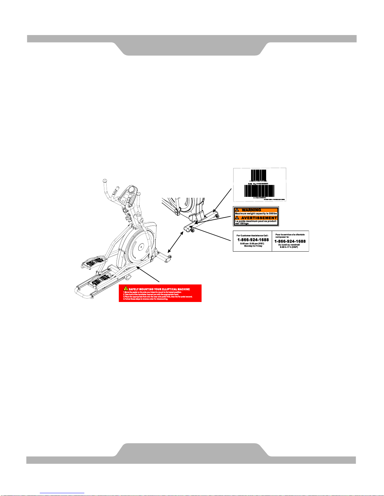
IMPORTANT
3
Page 5

Basic precautions should always be followed, including the following safety
instructions when using this equipment: Read all instructions before using
this equipment.
1. Read all the instructions in this manual and do warm up exercises before using
this equipment.
2. Before exercise, in order to avoid injuring your muscles, warm-up exercise
for every muscle group is highly recommended. Please refer to the Warm
Up pages for pre and post workout.
3. Please make sure all components are not damaged and in working order before
use. This equipment should be placed on a flat surface while in use. Using a
mat or other material on the ground is recommended.
4. Please wear proper clothes and shoes when using this equipment; do not wear
clothes that might catch in any part of the equipment.
5. Do not attempt any maintenance or adjustments other than those described in
this manual. Should any problems arise, discontinue use and consult an
Authorized Service Representative.
6. Be careful when stepping on or leaving the pedals. Always hold the
handlebars first and make sure the pedal at your side is at its lowest position.
Step on the pedal, and stride over the main frame then step on the other pedal.
When using, please hold onto the handlebars. To ensure the pedals run
smoothly push or pull on the handlebars first, then follow with leg motion.
When stepping off the machine, make sure one pedal is at its lowest position
and step out of there before stepping out of the pedal at the highest position.
7. Do not use the equipment outdoors.
8. This equipment is for household use only.
9. Only one person should be on the equipment while in use.
10. Keep children and pets away from the product while in use. This machine
is designed for adults only. This product requires a minimum of 6 feet of
space for safe operation.
11. If you feel any chest pains, nausea, dizziness, or short of breath, you should
stop exercising immediately and consult your physician before continuing.
12. The maximum weight capacity for this product is 350 lbs/159 kgs.
WARNING: Before beginning any exercise program consult your
physician. This is especially important for the persons who are over 35
years old or who have pre-existing health problems. Read all instructions
before using any fitness equipment.
CAUTION: Read all instructions carefully before operating this
product. Retain this Owner’s Manual for future reference.
PRODUCT SAFETY
4
Page 6

PART DRAWING
5
Page 7
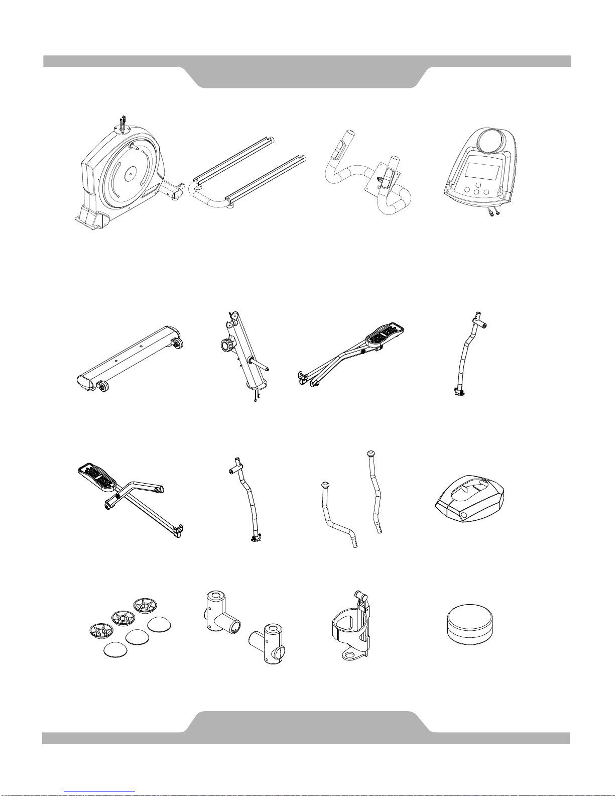
BOX CONTENTS
6
BOX A
BOX B
(B5) Left Foot
Bar Set
1 SET
(B1) Front Stabilizer Set
1 SET
(B2) Front Post Set
1 SET
(B3) Right Foot
Bar Set
1 SET
(B7) Handrails
1 SET
(68/69) Right/Left Front
Post Decorative Covers
1 SET
(78/79) Handrail Arm
Decorative Covers-A/B
2 SETS
(88) Bottle Holder
1 PC
(72) Nut Cap
M8x45
6 PCS
Lubricant
1 PC
(B4) Right Handrail Arm Set
1 SET
(B6) Left Handrail Arm Set
1 SET
(A1) Main Body
1 SET
(A2) M Shape Rail Set
1 SET
(A3) Hand Pulse
Handlebar Set
1 SET
(99) Computer
1 PC
Page 8

BOX CONTENTS
7
BOX B INCLUDED HARDWARE & TOOLS
(35) Bolt 3/8"x64mm
2 PCS
(36) Washer 3/8"x20x2.0T
4 PCS
(37) Cap Nut 3/8"x17T
2 PCS
(43) Bolt M8x50mm
4 PCS
(44) Nylon Nut M8x7.7T
4 PCS
(45) Curve Washer
M8x20x1.5T
4 PCS
(47) Hexagon Head Bolt
M8x16mm
4 PCS
(48) Washer 5/16"x20x2.0T
4 PCS
(55) Bolt M5x16mm
10 PCS
(106) Bolt M8x25mm
2 PCS
Allen Wrench (M4)
1 PC
Allen Wrench (M5)
1 PC
Hex Tool with Phillips Screwdriver
(13mm/14mm)
1 PC
Page 9
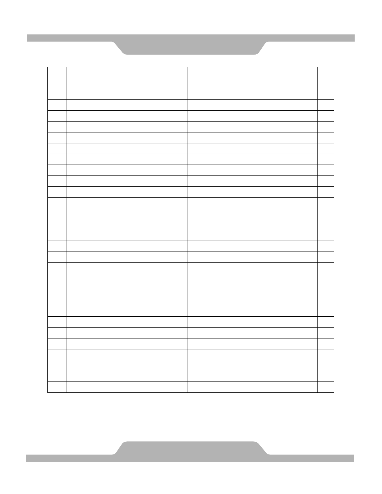
No.
Description
Qty
No.
Description
Qty
001
Main Frame
1
030
Nut M12x11.8T
2
002
Front Post
1
031
Countersunk Bolt M8x20mm
2
003
Left Handrail Arm
1
032
Bolt M5x10mm
4
004
Right Handrail Arm
1
033
U Bracket
2
005
Left Foot Bar
1
034
Nut M6x6.0T
2
006
Right Foot Bar
1
035
Bolt 3/8"x64mm
2
007
Left Rotate Bar
1
036
Washer 3/8"x20x2.0T
4
008
Right Rotate Bar
1
037
Cap Nut 3/8"x17T
2
009
Front Stabilizer
1
038
Bolt M6x15mm
8
010
Belt Pulley Shaft
1
039
Bolt M8x92
2
011
Crank
2
040
Nut M8x6.3T
1
012
U Shape Rail
1
041
Nut M10xP1.5x10T
3
013
Left Handrail
1
042
C Clip 17
1
014
Right Handrail
1
043
Bolt M8x50mm
4
015
Hand Pulse Handlebar
1
044
Nylon Nut M8x7.7T
10
016
Idle Wheel Bracket
1
045
Curve Washer M8x20x1.5T
12
017
Bolt 1/4"x1-3/4"(44mm)
2
046
Handrail Arm Axle
2
018
Washer 1/4"x16x1.5T
4
047
Hexagon Head Bolt M8x16mm
6
019
Nut 1/4"x8.0T
2
048
Washer 5/16"x20x2.0T
12
020
Bolt M6x45mm
2
049
Bolt M10x50mm
2
021
C Clip 20
1
050
Bolt M8x10mm
4
022
Wave Washer M21x30.0x0.4T
2
051
Bolt M3x25mm
2
023
Washer M20x26x1.0T
1
052
Bolt 3/16"x2"
1
024
Washer 38x10x2.0t
1
053
Bolt M3x16mm
2
025
Bolt M8x35mm
1
054
Bolt M4x16mm
2
026
Bolt M10x25mm
1
055
Bolt M5x16mm
27
027
Bolt M12x70mm
2
056
Bolt M8x16mm (NYLOK Patch)
8
028
Bolt M8x16mm
2
057
Rotate Bar Wheel Spacer
2
029
Washer 1/2x23x2.0T
6
058
Small Round Plastic Cover
2
PART LIST
8
Page 10

No.
Description
Qty
No.
Description
Qty
059
Hexagon Head Bolt M8x20mm
4
085
Bearing Bushing
10
060
Bolt M5x12mm
2
086
Bearing Fixed Bushing
10
061
Bolt M5x90mm
1
087
Axle Bushing
6
062
Nut 3/8x26
2
088
Bottle Holder
1
063
Left Shroud
1
089
Foot Pedal Plug
24
064
Right Shroud
1
090
Front Stabilizer End Cap
Ø50xØ100
4
065
Round Plastic Disk
2
091
Adjustable Leveler M8/12.5
2
066
Adjustable Leveler M8/16.5
4
092
Square End Cap 20x40
2
067
Transport Wheel
2
093
Sensor Wire I
1
068
Left Front Post Decorative Cover
1
094
Sensor Wire II
1
069
Right Front Post Decorative
Cover
1
095
Tension Control Knob
1
070
Oval End Cap Ø30xØ70x2.0mm
6
096
Tension Cable
1
071
Belt 520xJ7
1
097
Hand Pulse Sensor Wire
2
072
Nut Cap M8x45
6
098
Hand Pulse Sensor 9B
2
073
Foot Pedal
2
099
Computer ST7655
1
074
Hand Pulse Handlebar Foam
Grip (HDR) 30x3x510mm
2
100
Flywheel
1
075
Hand Pulse Handlebar End Cap
1-1/4"
2
101
Bearing 6004
2
076
Handrail Foam (HDR)
30x3x760mm
2
102
Bearing 6003
10
077
Handrail End Cap
2
103
Bearing 6001
4
078
Handrail Arm Decorative
Cover-A
2
104
Bearing 6203
2
079
Handrail Arm Decorative
Cover-B
2
105
M Shape Rail Aluminum Plate
2
080
Belt Pulley Ø360
1
106
Bolt M8x25mm
2
081
Rotate Bar Wheel Ø65
2
107
L Shape Plate for Left Rotate Bar
1
082
Bushing
12
108
L Shape Plate for Right Rotate Bar
1
083
Plastic Washer 14x20x2.0
4
109
Bolt M8x25mm
4
084
Spacer
6
110
Washer
2
PART LIST
9
Page 11
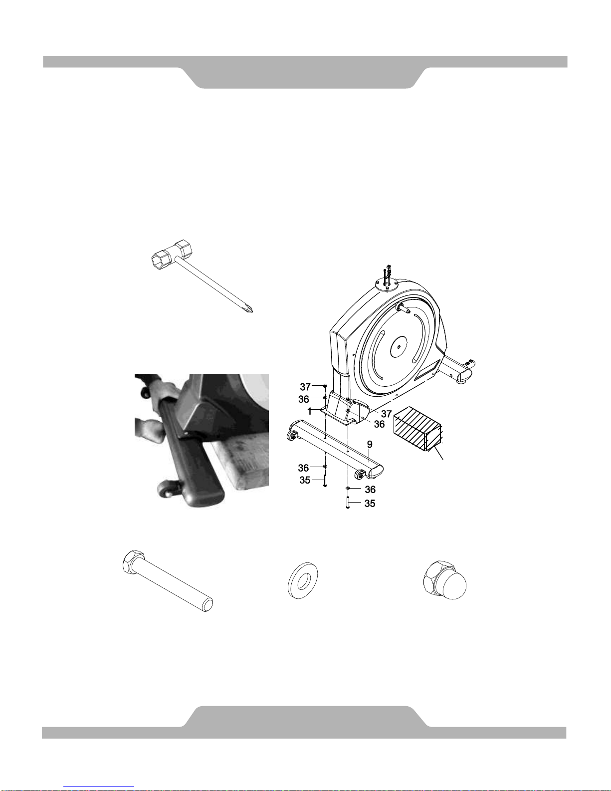
1. Front Stabilizer Installation
Place a block of wood to raise the main body for easier to install the Front
Stabilizer (9).
Position the Front Stabilizer (9) in front of Main Frame (1) and align bolt holes.
Attach the Front Stabilizer (9) onto the front curve of the Main Frame (1) with two
3/8"x64mm Bolts (35), four 3/8"x20x2.0T Washers (36), and two 3/8"x17T Cap
Nuts (37). Tighten bolts with the Hex Tool with Phillips Screwdriver provided.
Hardware:
ASSEMBLY
10
(35) Bolt 3/8"x64mm
2 PCS
(36) Washer 3/8"x20x2.0T
4 PCS
(37) Cap Nut 3/8"x17T
2 PCS
Hex Tool with Phillips
Screwdriver (14mm)
Tool:
Block of Wood
Page 12
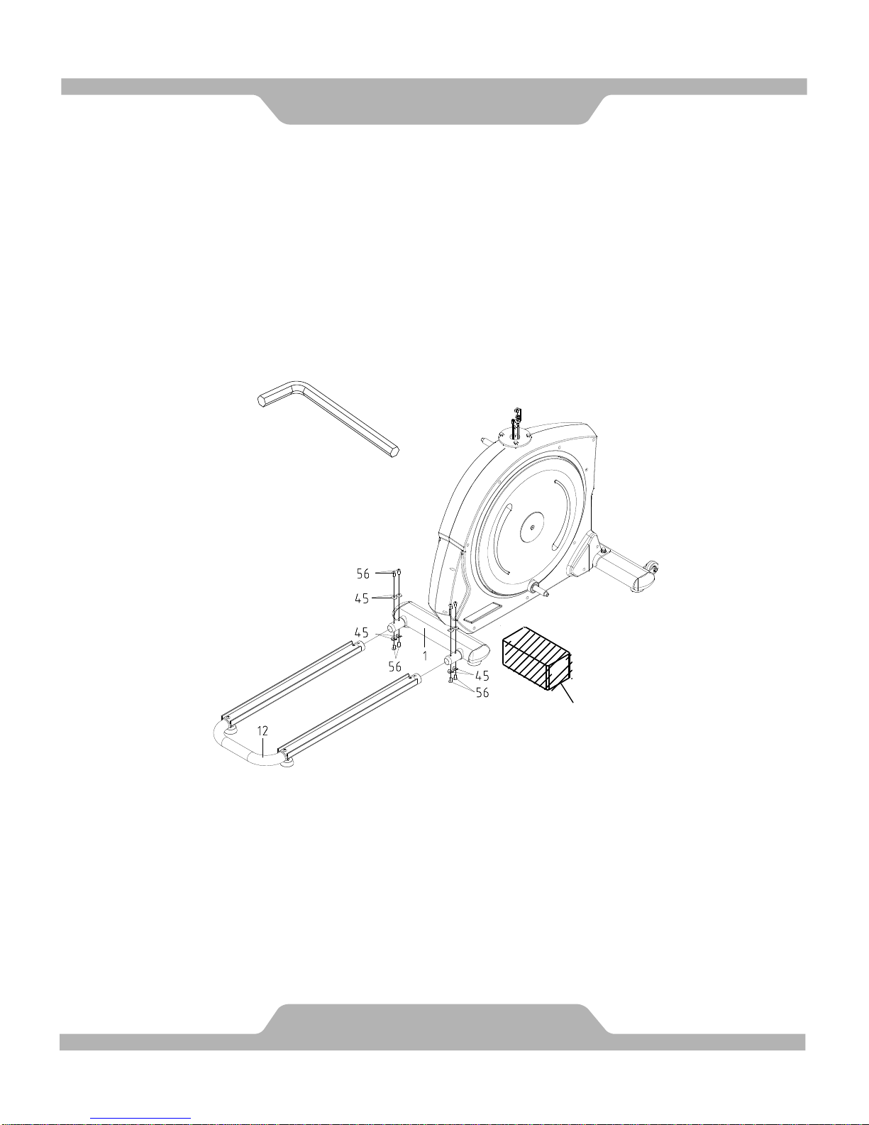
2. U Shape Rail Installation
Place a block of wood to raise the main body for easier to install the U Shape
Rail (12).
Remove eight M8x20x1.5T Curve Washers (45) and eight M8x16mm Bolts (56)
from the Main Frame (1). Remove bolts with the M5 Allen Wrench provided.
Attach the U Shape Rail (12) onto the tubes of the Main Frame (1) with eight
M8x20x1.5T Curve Washers (45) and eight M8x16mm Bolts (56) that were
removed. Tighten bolts with the M5 Allen Wrench provided.
ASSEMBLY
11
Allen Wrench (M5)
Tool:
Block of Wood
Page 13
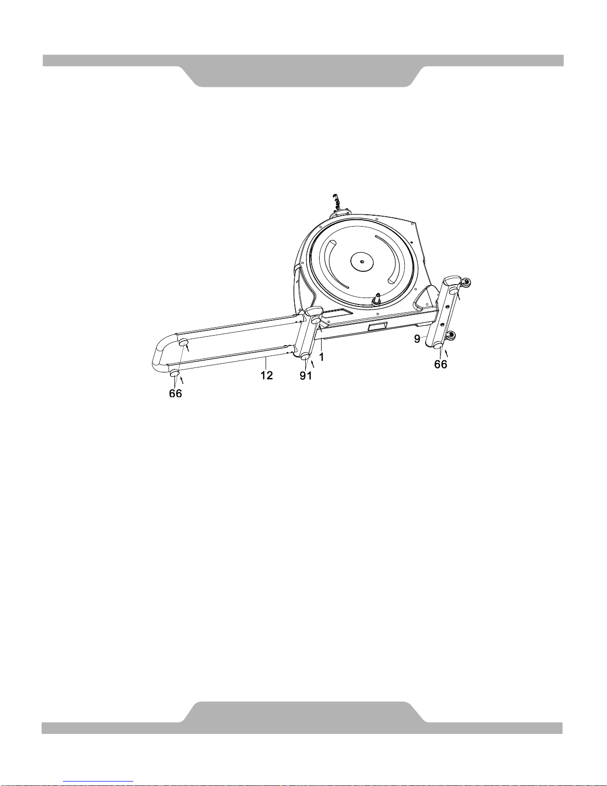
3. Adjusting the Adjustable Leveler
Turn the Adjustable Levelers (66, 91) on the Front Stabilizer (9), Main Frame
(1), or U Shape Rail (12) as needed to level the elliptical trainer. The elliptical
trainer has to be leveled to prevent from wobble or shaking during the
exercise.
ASSEMBLY
12
Page 14
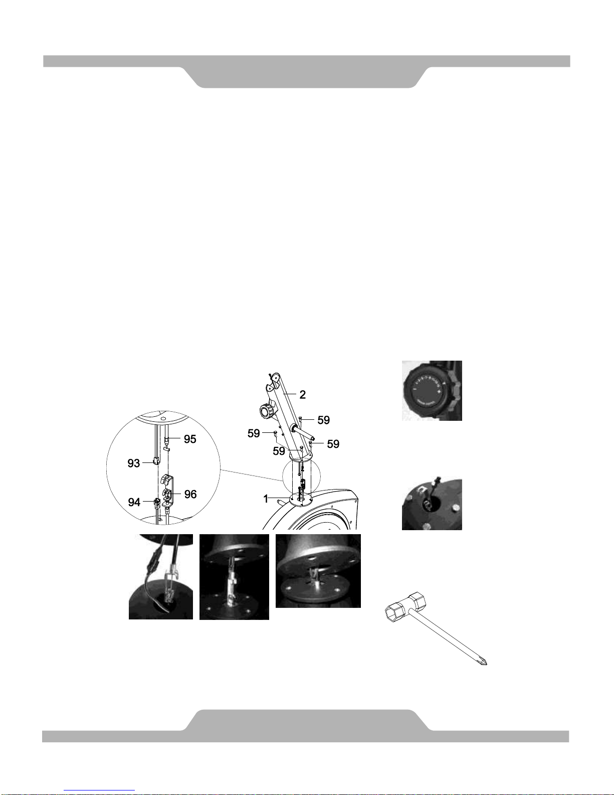
4. Front Post and Tension Control Knob Installation
Remove four M8x20mm Bolts (59) from the Main Frame (1). Remove bolts
with the Hex Tool with Phillips Screwdriver provided.
Pull out the Tension Cable (96) and Sensor Wire II (94) from the Main Frame
(1).
Put the cable end of resistance cable of Tension Control Knob (95) into the
spring hook of Tension Cable (96) and then pull the resistance cable of
Tension Control Knob (95) up and force it into the gap of metal bracket of
Tension Cable (96).
Connect the Sensor Wire II (94) from the Main Frame (1) to the Sensor
Wire I (93) from the Front Post (2) and carefully tuck the wires into the Main
Frame (1) before attaching the Front Post (2) onto the Main Frame (1).
Attach the Front Post (2) onto the Main Frame (1) with four M8x20mm Bolts
(59) that were removed.
NOTE: PLEASE DO NOT FULLY TIGHTEN M8x20MM BOLTS (59) WITH
THE HEX TOOL WITH PHILLIPS SCREWDRIVER PROVIDED, ONLY
HAND TIGHTEN.
ASSEMBLY
13
Hex Tool with Phillips
Screwdriver (13mm)
Tool:
Pull out the Tension
Cable (96) connector
and Sensor Wire II (94).
Set the Tension Control
Knob (95) to the highest
level & connect the
Tension Cable (96).
Carefully tuck the wires into
the Main Frame (1) before
attaching the Front Post (2)
onto the Main Frame (1).
Page 15
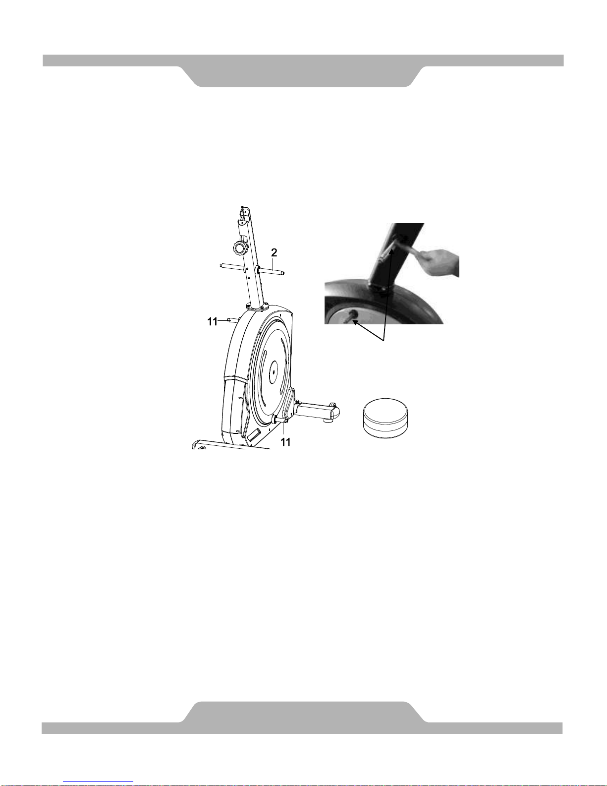
5. Lubricating the Horizontal Axle and Crank Axle
Put some lubricants onto both horizontal axles of the Front Post (2) and both
axles of the Crank (11).
Remark: Gently apply lubricant evenly on Front Post (2). Brush tool is
recommended.
ASSEMBLY
14
Lubricant
1 PC
Lubricating the horizontal
axle and crank axle.
Page 16
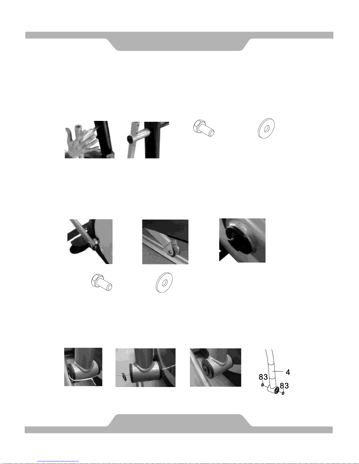
6. Right and Left Foot Bar Sets Installation
Remove the tape from the joint of the Right Handrail Arm (4).
Insert the Right Handrail Arm (4) all the way onto the horizontal axle of the
Front Post (2) and secure the Right Handrail Arm (4) in position with one
M8x16mm Hexagon Head Bolt (47) and one 5/16"x20x2.0T Washer (48).
Tighten bolt with the Hex Tool with Phillips Screwdriver provided.
Remove the tape from the joint of the Right Rotate Bar (8).
Insert the Right Rotate Bar (8) onto the Crank (11) axle. The Rotate Bar
Wheel (81) has to be placed on the M Shape Rail Aluminum Plate (105).
Secure the Right Rotate Bar (8) in position with one M8x16mm Hexagon
Head Bolt (47) and one 5/16"x20x2.0T Washer (48). Tighten bolt with the
Hex Tool with Phillips Screwdriver provided.
Untie the wire and remove two 14x20x2.0 Plastic Washers (83) and wire
from the bottom end of the Right Handrail Arm (4). Place two 14x20x2.0
Plastic Washers (83) back onto the joint of the Right Handrail Arm (4).
ASSEMBLY
15
(47) Hexagon Head Bolt
M8x16mm
1 PC
(48) Washer
5/16"x20x2.0T
1 PC
Untie the
wire.
Remove the
wire and Plastic
Washers (83).
Place two Plastic
Washers (83) back onto
the joint of the Right
Handrail Arm (4).
CAUTION: MAKE SURE
THE BUSH (82) WAS
PERFECTLY IN POSITION
BEFORE SECURING THE
BOLTS.
(47) Hexagon Head Bolt
M8x16mm
1 PC
(48) Washer
5/16"x20x2.0T
1 PC
Page 17
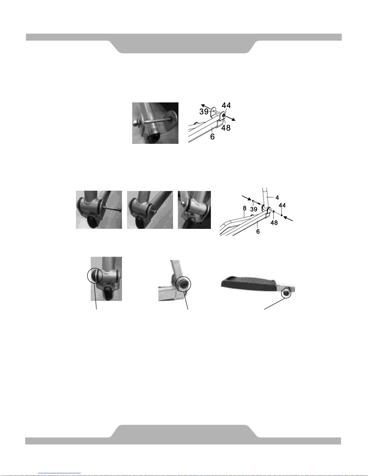
Remove one M8x92 Bolt (39), one M8x7.7T Nylon Nut (44), and one
5/16”x20x2.0T Washer (48) from the Right Foot Bar (6). Remove bolt and
nylon nut with the Hex Tool with Phillips Screwdriver and M5 Allen wrench
provided.
Pull the Right Foot Bar (6) up onto the Right Handrail Arm (4) and align bolt
holes. Then attach the Right Foot Bar (6) onto the Right Handrail Arm (4)
with one M8x92 Bolt (39), one M8x7.7T Nylon Nut (44), and one
5/16”x20x2.0T Washer (48) that were removed. Tighten bolt and nylon nut
with the Hex Tool with Phillips Screwdriver and M5 Allen wrench provided.
Install three M8x45 Nut Caps (72) onto one M8x7.7T Nylon Nut (44) and two
M8x16mm Hexagon Head Bolts (47).
Repeat above steps to install the Left Handrail Arm (3) onto the horizontal axle
of the Front Post (2) and Left Rotate Bar (7) onto the Crank (11) axle.
NOTE: PLEASE FULLY TIGHTEN M8x20MM BOLTS (59) WITH THE HEX
TOOL WITH PHILLIPS SCREWDRIVER PROVIDED IN STEP 4.
ASSEMBLY
16
M8x45 Nut Cap (72)
M8x45 Nut Cap (72)
M8x45 Nut Cap (72)
Page 18
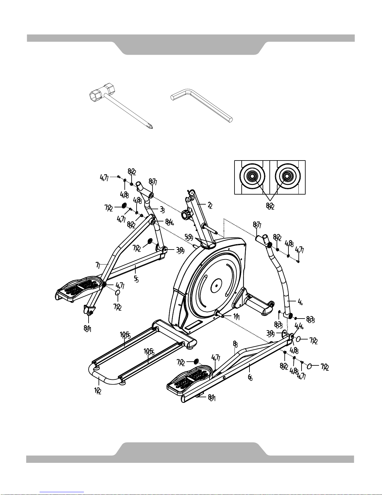
ASSEMBLY
17
INCORRECT
CORRECT
Hex Tool with Phillips
Screwdriver (13mm)
Tool:
Allen Wrench (M5)
Page 19
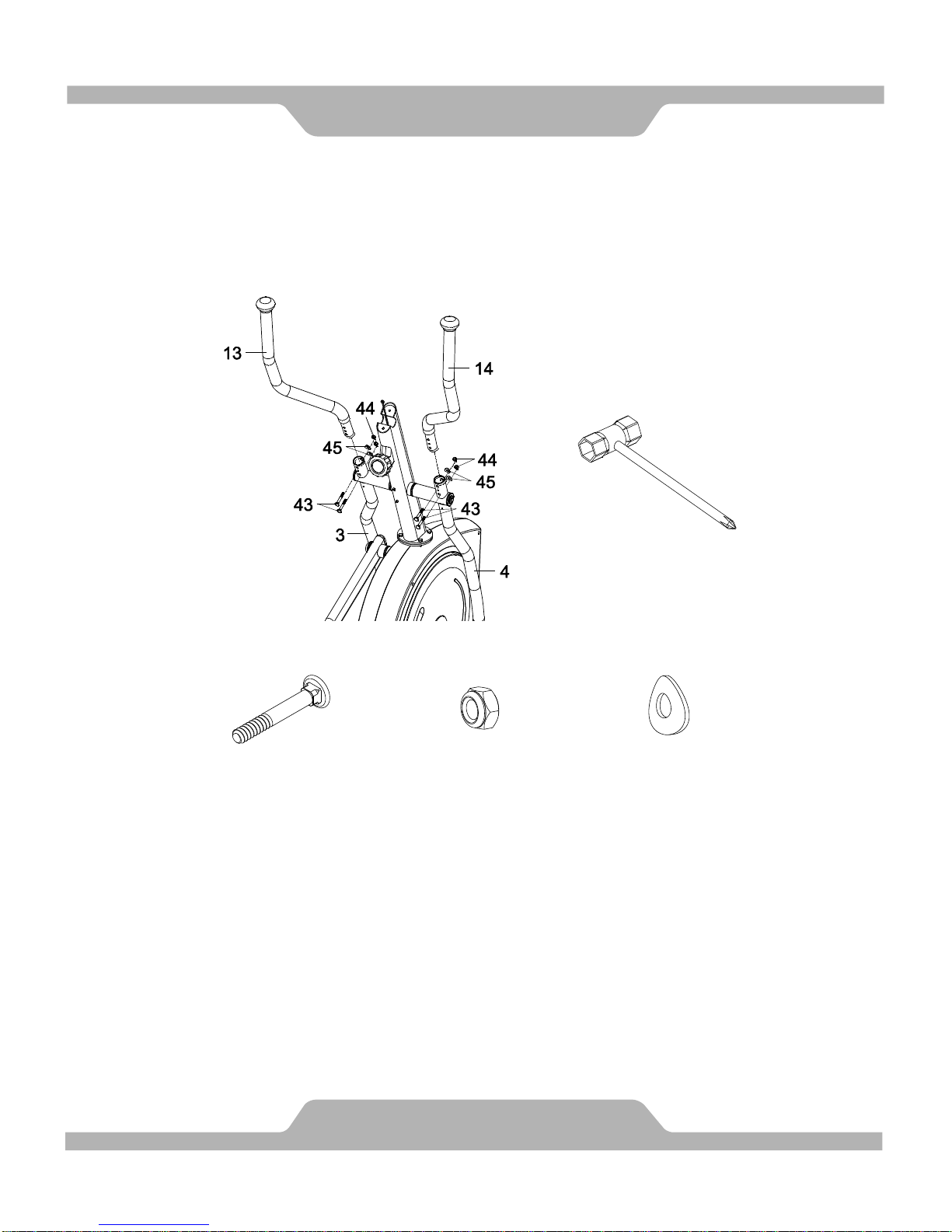
7. Left and Right Handrails Installation
Attach the Left/Right Handrails (13, 14) into the Left/Right Handrail Arms
(3, 4) with four M8x50mm Bolts (43), four M8x7.7T Nylon Nuts (44), and four
M8x20x1.5T Curve Washers (45). Tighten nylon nuts with the Hex Tool with
Phillips Screwdriver provided.
Hardware:
ASSEMBLY
18
(43) Bolt M8x50mm
4 PCS
(44) Nylon Nut M8x7.7T
4 PCS
(45) Curve Washer
M8x20x1.5T
4 PCS
Hex Tool with Phillips
Screwdriver (13mm)
Tool:
Page 20
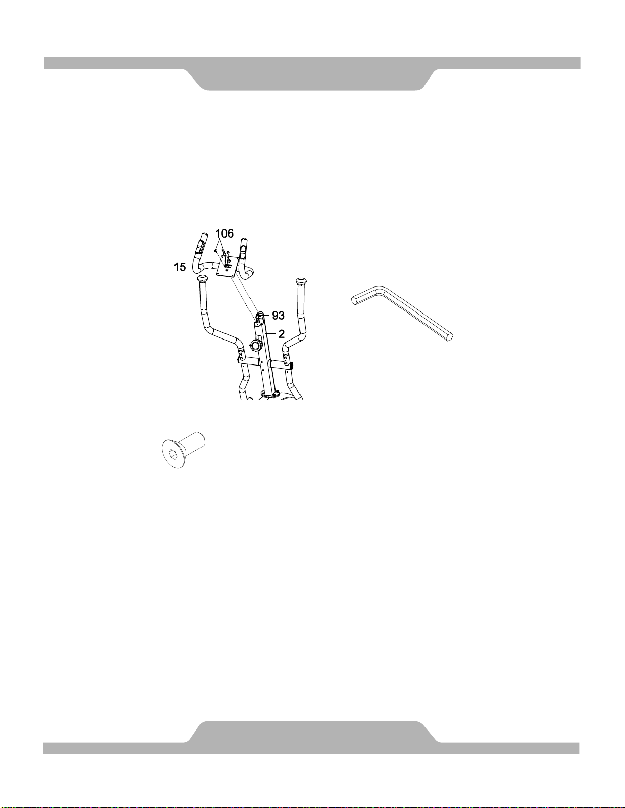
8. Hand Pulse Handlebar Installation
Insert the Sensor Wire I (93) from the Front Post (2) into the hole on the
Hand Pulse Handlebar (15) and then pull it out from the Hand Pulse
Handlebar (15).
Attach the Hand Pulse Handlebar (15) onto the Front Post (2) with two
M8x25mm Bolts (106). Tighten bolts with the M5 Allen Wrench provided.
Hardware:
ASSEMBLY
19
(106) Bolt M8x25mm
2 PCS
Allen Wrench (M5)
Tool:
Page 21
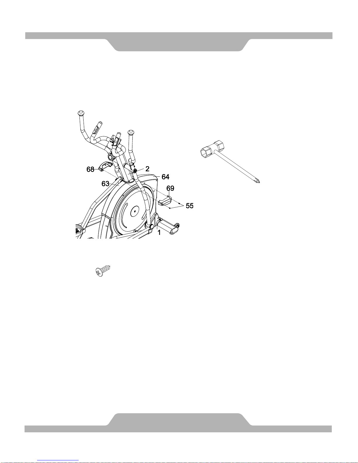
9. Left/Right Front Post Decorative Covers Installation
Attach the Left/Right Front Post Decorative Covers (68, 69) onto the Front
Post (2) with two M5x16mm Bolts (55). Tighten bolts with the Hex Tool
with Phillips Screwdriver provided.
Hardware:
ASSEMBLY
20
(55) Bolt M5x16mm
2 PCS
Hex Tool with Phillips Screwdriver
Tool:
Page 22
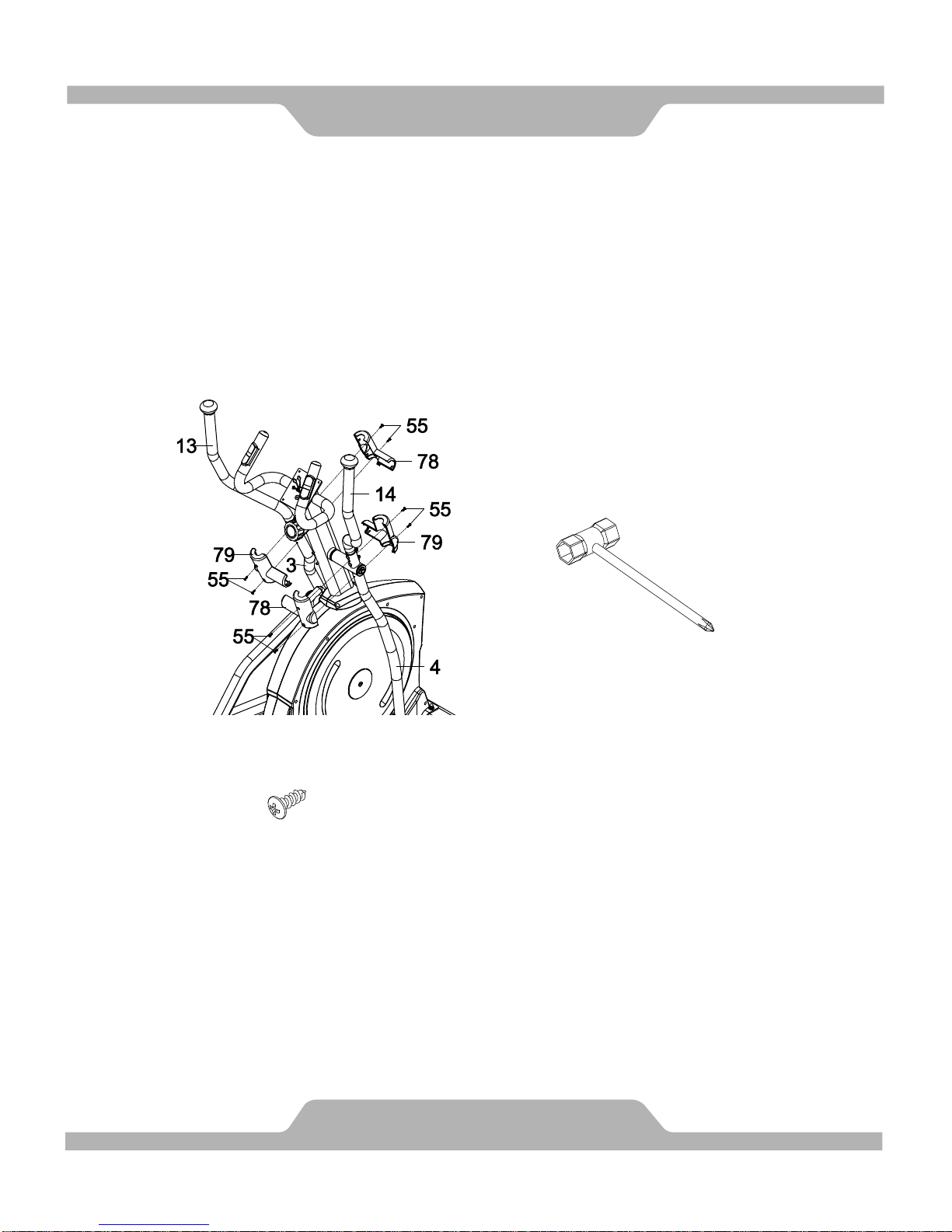
10. Handrail Arm Decorative Covers-A/B Installation
Attach the Handrail Arm Decorative Cover-A (78) and Handrail Arm
Decorative Cover-B (79) onto the Left Handrail Arm (3) with four M5x16mm
Bolts (55). Tighten bolts with the Hex Tool with Phillips Screwdriver
provided.
Attach the Handrail Arm Decorative Cover-A (78) and Handrail Arm
Decorative Cover-B (79) onto the Right Handrail Arm (4) with four
M5x16mm Bolts (55). Tighten bolts with the Hex Tool with Phillips
Screwdriver provided.
Hardware:
ASSEMBLY
21
(55) Bolt M5x16mm
8 PCS
Hex Tool with Phillips Screwdriver
Tool:
Page 23
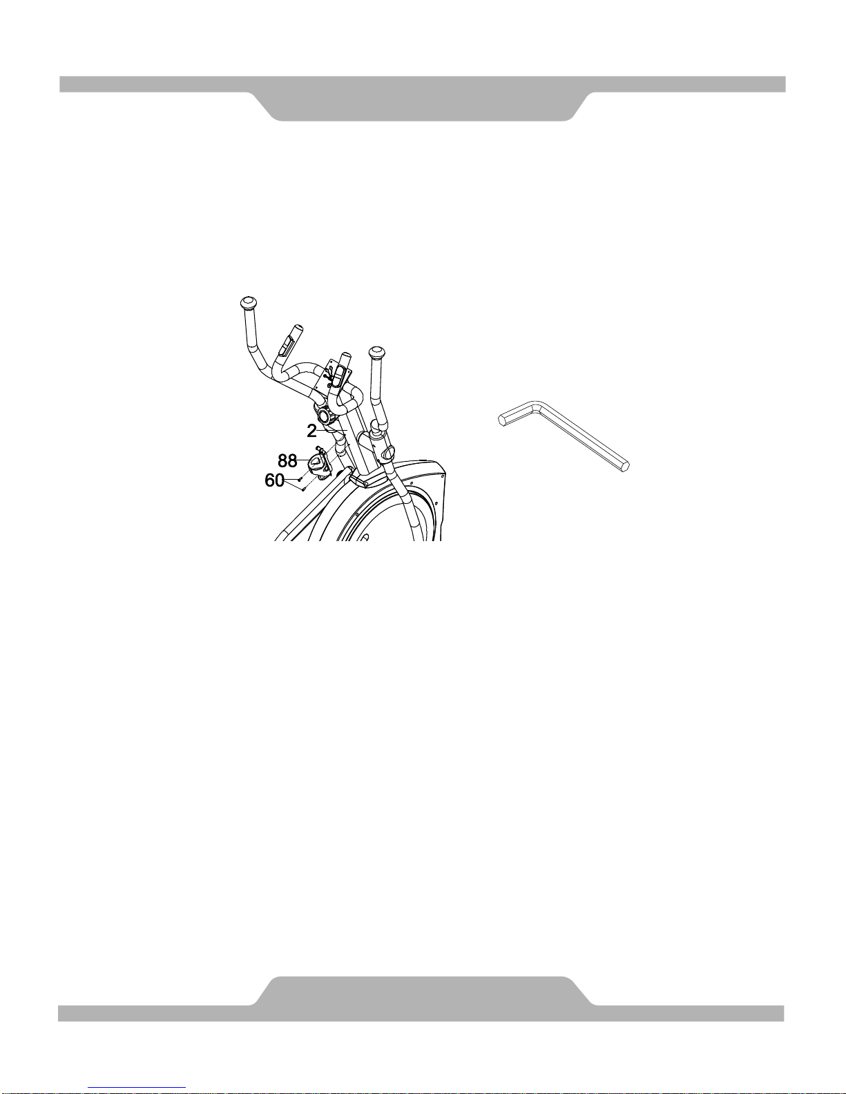
11. Bottle Holder Installation
Remove two M5x12mm Bolts (60) from the Front Post (2). Remove bolts
with the M4 Allen Wrench provided.
Attach the Bottle Holder (88) onto the Front Post (2) with two M5x12mm
Bolts (60) that were removed. Tighten bolts with the M4 Allen Wrench
provided.
ASSEMBLY
22
Allen Wrench (M4)
Tool:
Page 24
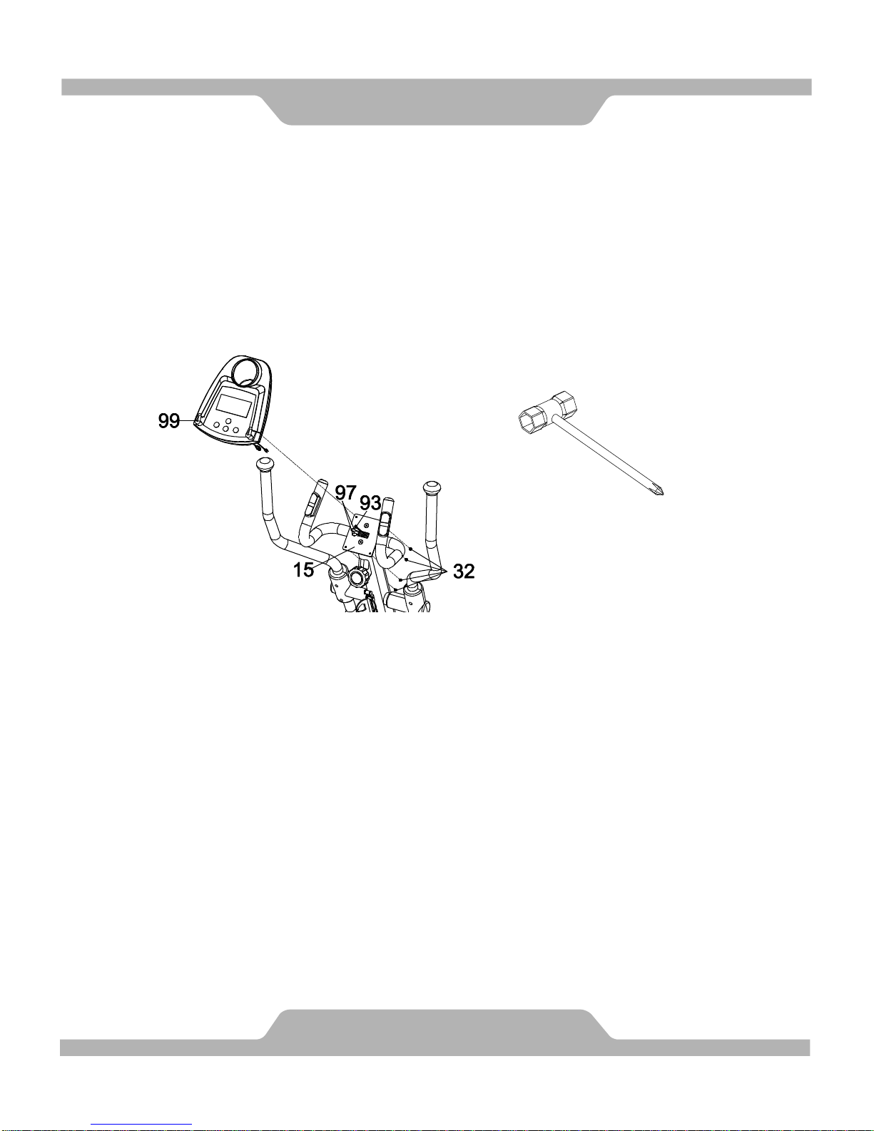
12. Computer Installation
Remove four M5x10mm Bolts (32) from the back of the Computer (99).
Remove bolts with the Hex Tool with Phillips Screwdriver provided.
Connect the Sensor Wire I (93) and Hand Pulse Sensor Wires (97) to the
wires that come from the Computer (99) and then attach the Computer (99)
onto the top end of the Hand Pulse Handlebar (15) with four M5x10mm
Bolts (32) that were removed. Tighten bolts with the Hex Tool with Phillips
Screwdriver provided.
ASSEMBLY
23
Hex Tool with Phillips Screwdriver
Tool:
Page 25
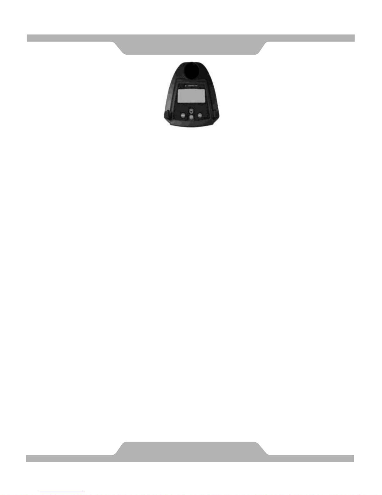
BUTTON FUNCTIONS:
MODE: Press the "Mode" button to change modes and to confirm setup.
SET: Used to set the values for TIME, DISTANCE, CALORIES and PULSE.
You can hold the button to increase the value at a faster rate. (Only works
while machine is stopped.)
RESET: "Reset" clears the current value on any of: Time, Distance or Calories.
Pushing the button once clears one value, holding it down for 2 seconds
clears all. (When the user replace batteries, all the values will reset
to ZERO automatically.)
RECOVRY: An after workout cool down function. Gives a 1 minute cool down.
DISPLAY FUNCTIONS:
SCAN: Scans continuously through all functions RPM - SPEED - DISTANCE -
CALORIES - PULSE.
RPM: Displays total Revolutions Per Minute. The display will automatically
switch between RPM and SPEED every 6 seconds after starting to exercise.
SPEED: Displays current speed.
TIME: Count up - Without a preset time, time will count up from 00:00 to a maximum
of 99:59.
TIME can be preset in 1 minute increments between 01:00 and 99:00.
DISTANCE: Shows total accumulated distance from 00:00 up to 99.99 miles.
The user may preset target distance by pressing the UP/DOWN button,
done in 0.1 mile increments.
CALORIES: Show total accumulated burned calories during training from 0 to
maximum of 9999 calories. (This data is a rough guide for comparison
of different exercise sessions. It can not be used in medical treatment
or for exact measurements.)
PULSE: Displays your current pulse.
TEMPERATURE: Displays current room temperature from 32F to 140F.
CALENDAR: You can set a current calendar including year, month, date, and it will
display after the monitor auto-shuts off, after about 4 minutes.
To set up the time: Press the set button for 3 seconds.
CLOCK: Displays hour and minute from 00:00 to 23:59 (24 hours mode).
COMPUTER
24
Page 26
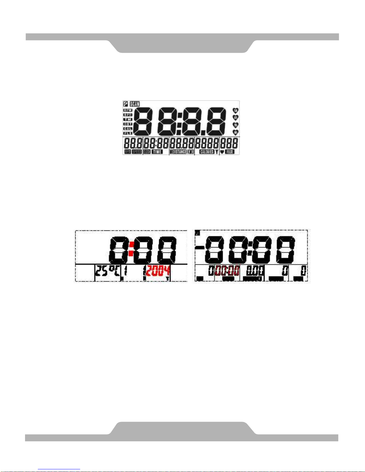
SET UP TIME:
1. After installing 2 AA batteries the screen will display the following
(see Drawing A) and make a short high pitched sound.
2. The calendar display will blink on and off as shown in "Drawing B". You
are able to press the SET button to change the numbers. You can also
press the RESET button to return to the original value. Pressing the "MODE"
button will switch between Month, Date, Hour and Minutes. The setup process
is the same for the year. Press the "MODE" button to confirm setup.
(see Drawing C).
PROGRAM:
Gives you access the setup mode for TIME, DISTANCE, CALORIES and TARGET
PULSE. When you are in each setup mode, for instance the time setup, when
the time value is blinking, you can press the "SET" button to adjust the number.
Press the "MODE" button to confirm and move to the next part of setup. The
setup for DISTANCE & CALORIES is the same as for TIME.
1. TIME mode: Count down - With preset Time, Time will count down from the
preset value to 00:00.
Preset values are chosen in 1 minute increments, between 01:00 to 99:00.
2. DISTANCE mode:
Count down - With preset distance, distance will count down from the preset
value to 0.
Preset values are chosen in 0.5 mile increments, between 0.5 to 99.50 miles.
COMPUTER
25
Drawing A
Drawing B
Drawing C
Page 27
3. CALORIES mode: Count down - With preset calories, calories will count
down from the preset value to 0.
Preset values are chosen in 10 calorie increments, between 10 to 9990
calories.
4. PULSE mode: Preset values are chosen in 10 BPM (Beats Per Minute)
increments, between 30 to 240 BPM.
Once the current pulse reading exceeds the preset value the computer will
begin to beep.
5. RECOVERY:
(1) The "RECOVERY" button functions as a cool down feature. It will help you
cool down after you are finished with your workout. During this cool down,
only time and pulse will be displayed. TIME will begin to count down from
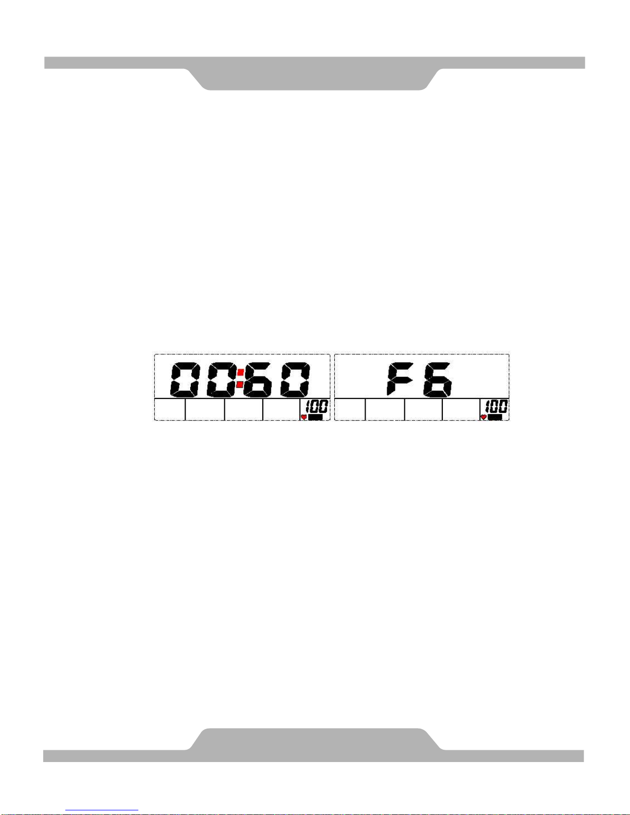
00:60, and the pulse reading will blink With the users current pulse. When
the countdown reaches "0", it will show "F6" and display nothing else until
you push another button. This is the end of the workout.
(2) LCD display as follows: (RECOVERY start condition & end condition)
(3) If you leave early and there is no pulse when the timer hits 00:00 then to
start again you will need to push the RECOVERY button again.
(4) If you push the RECOVERY button before the timer has finished it resets
the cool down and clears out the presets.
NOTE:
1. If you stop training for 4 minutes, the main screen will turn off and display the
current temperature.
2. If the computer display seems abnormal or unintelligible, please re-install the
batteries and try again.
3. Battery Spec: 1.5V AA or UM-3 (2 PCS)
COMPUTER
26
Page 28
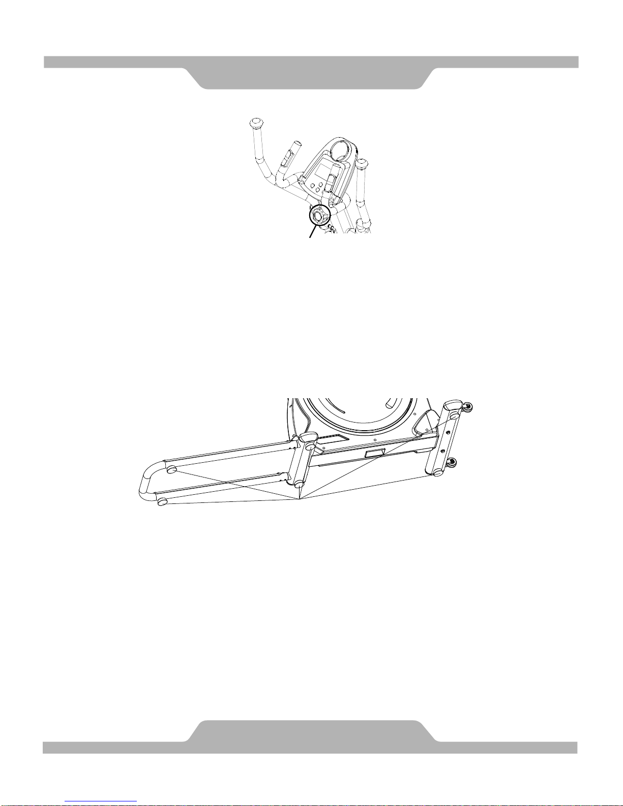
Adjusting the Tension Control Knob
To increase the load, turn the tension control knob in a clockwise direction.
To decrease the load, turn the tension control knob in a counterclockwise
direction.
Adjusting the Adjustable Leveler
Turn the adjustable leveler on the front stabilizer, main frame, or U shape rail
as needed to level the elliptical trainer. The elliptical trainer has to be leveled
to prevent from wobble or shaking during the exercise.
ADJUSTMENTS
27
Tension Control Knob
Adjustable Leveler
Page 29

TROUBLE SHOOTING
Computer not working correctly
Check to make sure the computer cable is connected securely.
Make sure the batteries are installed correctly.
Make sure the batteries are not dead.
The elliptical trainer wobbles when in use
Turn the adjustable leveler on the front stabilizer, main frame, or U shape rail
as needed to level the elliptical trainer.
Squeaking noise when in use
The bolts may be loose on the elliptical trainer, please inspect the bolts and tighten
the loose ones.
No, inconsistent, or erratic heart rate reading
Always hold on to the handlebar grip sensors with two hands instead of just one.
Try to maintain moderate pressure while holding onto the hand pulse sensors.
Make sure that the wire connections for the hand pulse sensors are secure.
No tension adjustment
There are 15 tension adjustment levels. If the tension remains the same for all
levels, that means the Tension Cable (96) did not install correctly. Please refer to
page 13.
MAINTENANCE
Cleaning
The elliptical trainer can be cleaned with a soft cloth and mild detergent. Do not use
abrasives or solvents on plastic parts. Please wipe your perspiration off the elliptical
trainer after each use. Be careful not get excessive moisture on the computer
display panel as this might cause an electrical hazard or electronics to fail. Please
keep the elliptical trainer, specially, the computer console, out of direct sunlight to
prevent screen damage. Please inspect all assembly bolts and pedals on the
machine for proper tightness every week.
Storage
Store the elliptical trainer in a clean and dry environment away from children.
TROUBLE SHOOTING &
28
Page 30
WARM UP
29
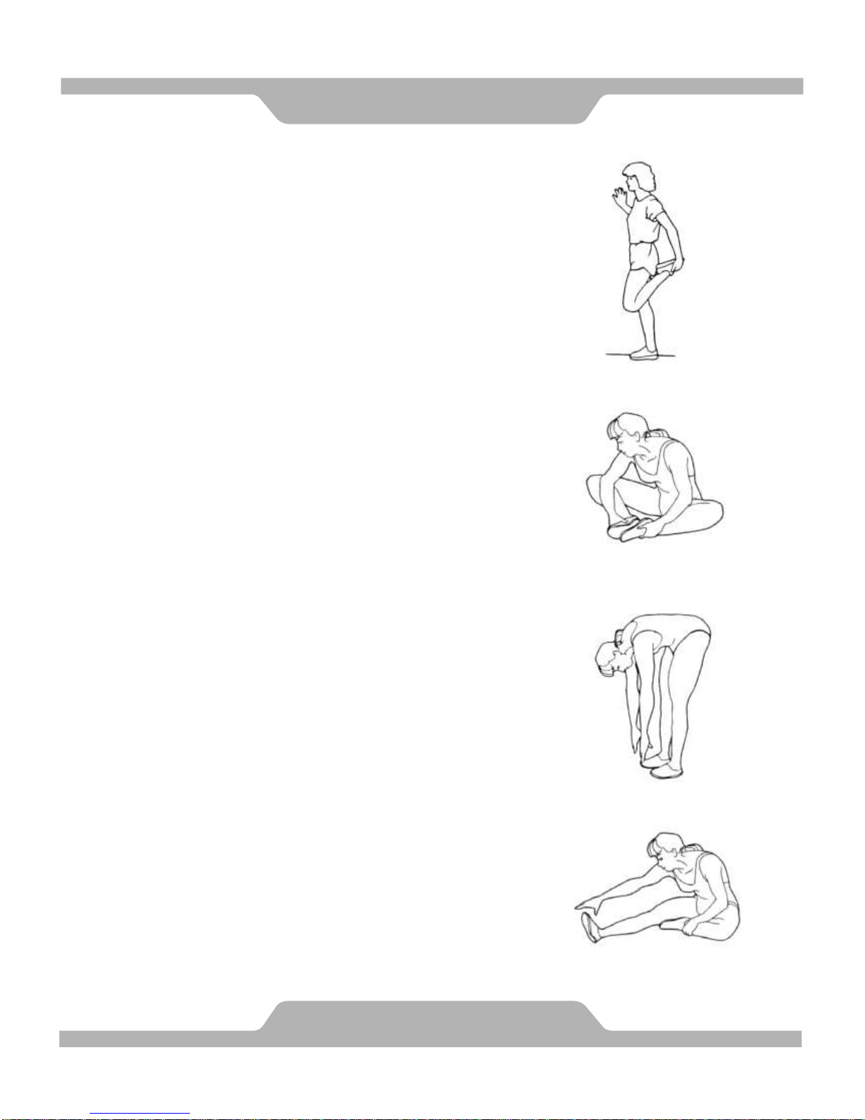
Quadriceps Stretch
With one hand against a wall for balance, reach behind
you and pull your right foot up. Bring your heel as close
to your buttocks as possible. Hold for 15 counts and
repeat with left foot up.
Inner Thigh Stretch
Sit with the soles of your feet together with your knees
pointing outward. Pull your feet as close into your groin
as possible.
Gently push your knees towards the floor. Hold for 10
counts.
Toe Touches
Slowly bend forward from your waist, letting you back and
shoulders relax as you stretch toward your toes. Reach
down as far as you can and hold for 15 counts.
Hamstring Stretches
Sit with your right leg extended. Rest the sole of your left
foot against your right inner thigh. Stretch toward your
toe as far as possible. Hold for 15 counts Relax and then
repeat with left leg extended.
Page 31

Paradigm Health & Wellness, Inc. warrants to the original purchaser that this product
is free from defects in material and workmanship when used for the purpose intended,
under the conditions that it has been installed and operated in according to
Paradigm’s Owner’s Manual. Paradigm’s obligation under this warranty is limited to
replacing free of charge, any parts which may prove to be defective under normal
home use. This warranty does not include any damage caused by improper
operation, misuse or commercial application. From the date of purchase, the frame,
welding , and brake system of this product is warranted to be free from defects for 3
(three) years. All other parts and workmanship, including electrics, upholstery, foam,
ball bearings, pulleys, cables, shocks, wheels, pedals and hardware are to be free
from defects for 180 days. This warranty is offered only to the original owner and is
not transferable. Proof of purchase is required.
Ordering Replacement Parts
Replacement parts can be ordered by calling or emailing our customer service
department
1-866-924-1688
Monday through Friday, 8:00 AM - 5:00 PM (PST).
When ordering replacement parts please have the following information ready:
1. Owner’s Manual
2. Model Number
3. Description of Parts
4. Part Number
5. Date of Purchase
WARRANTY
30
Page 32
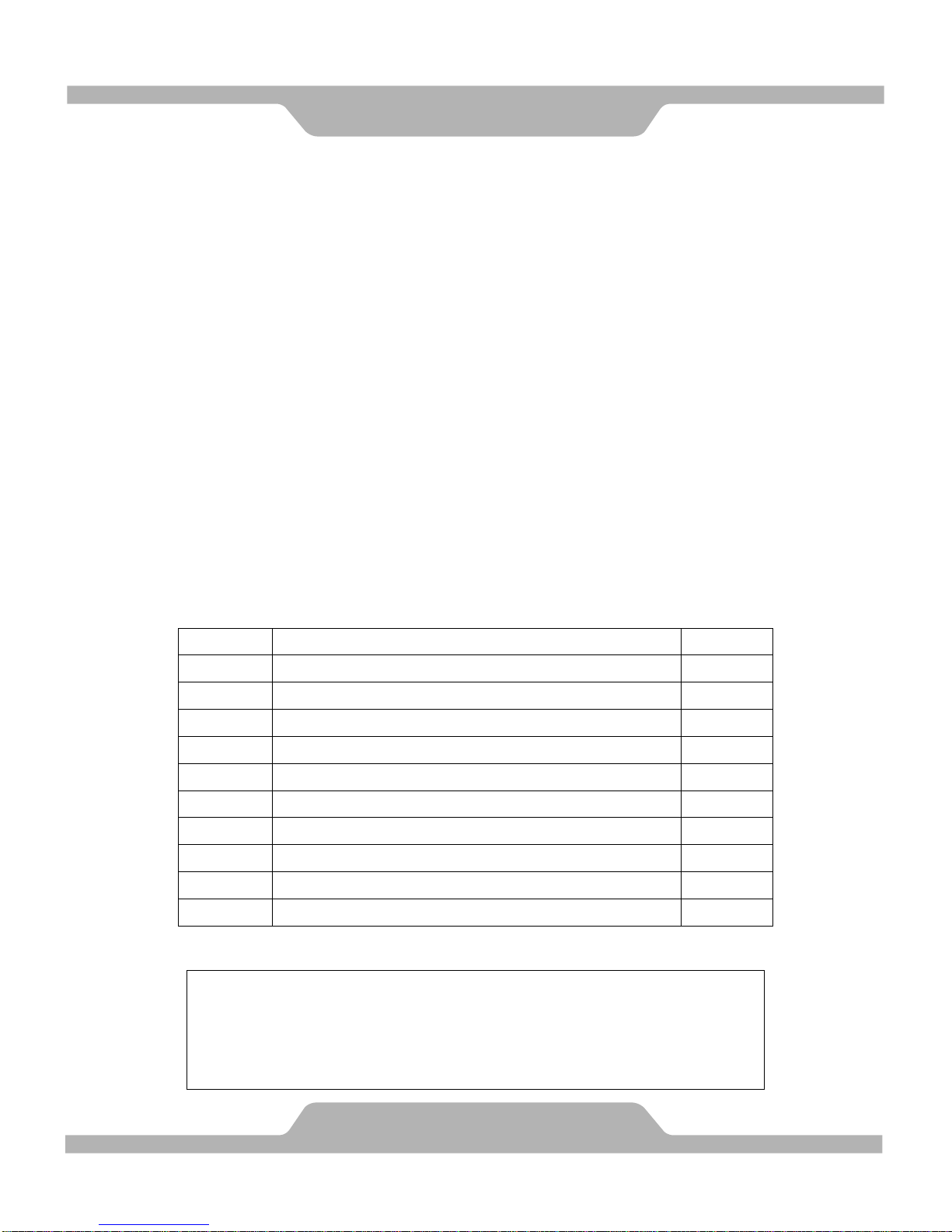
PARADIGM
PARTS REQUEST FAX FORM
Please fax this form to (1-626-810-2166)
OR YOU CAN EMAIL CUSTOMER SERVICE REQUESTS TO
NAME: _______________________________________________________
ADDRESS: ____________________________________________________
CITY ______________ STATE ______________ ZIP ___________________
TELEPHONE: (Day) _____________________________________________
(Night) ____________________________________________
(Email Address) ____________________________________
SERIAL#: __________________________________________
MODEL#: __________________________________________
PURCHASE DATE: ______________________________________________
PURCHASE FROM: ______________________________________________
“YOUR ORDER WILL BE PROCESSED WITHIN 3 BUSINESS DAYS”
PART #
DESCRIPTION
QTY
OFFICIAL USE ONLY
SHIP DATE: ___________________________________________
TRK #: _______________________________________________
BACK ORDER: ________________________________________
FAX FORM
31
 Loading...