


USER AND SERVICE MANUAL
FOR EXE-RISE CHAIN HOIST
250/500/1000/2000 kg
D8 (DC/LVC)
150/300/600/800/1200 kg
D8+ (DC/LVC)
EXCLUSIVELY DISTRIBUTED BY
LITEC ITALIA S.R.L.
Via Martin Luther King 70, I-31032 Casale sul Sile (TV), Italy
Tel: +390422997300 Fax: +390422997399
www.exetechnology.com
www.litectruss.com
[ORIGINAL INSTRUCTION]
2 / 64
MANUFACTURER IDENTIFICATION
RWM S.R.L.
Sede Legale: Via Bartolomeo Colleoni 80/7, 36034 Malo (VI), Italia
Sede Operativa: Via della Tecnica 15, 36034 Molina di Malo (VI), Italia
Tel: +39 0445 637 002 – Fax: +39 0445 637 019
www.rwmitalia.com
Retain this manual for future reference and use.
Forward this manual to the chain hoist operator and maintainer.
Should you have any questions or have problems with this product, please call RWM S.r.l..
Check the EXE website for the latest version of the manual or the manual related to the year of purchase
of your hoist.
Before using the hoist, please fill in the following information (referred to the hoist identification plate).
Such information must be communicated every time that the RWM S.r.l service department or your local
distributor is contacted. If you are in doubt or need any further information, please contact us.
Customer Name
and address (1)
Customer Name
and address (2)
Model number
Instructions for use
Serial number
Purchase date
Voltage
Nominal capacity
Revision
Modifications
Description
Issue Date
01
All manual
First issue in according to Machine Directive 2006/42/CE
29/11/2017
02
All manual
Update information
28/02/2018
Do not use a chain hoist before all operators have carefully read this manual.
Failure to operate the equipment as here described may cause injury or even death.

3 / 64
CONTENT
CONTENT OF FIGURES................................................................................................................................................ 5
CONTENT OF TABLE ..................................................................................................................................................... 6
1. GENERAL INFORMATION ................................................................................................................................... 7
1.1 MANUAL SCOPE ........................................................................................................................................... 7
1.2 CHAIN HOIST IDENTIFICATION ................................................................................................................ 8
1.3 SAFETY SIGNAL ........................................................................................................................................... 9
1.4 TERMS AND DEFINITIONS ......................................................................................................................... 9
1.5 REPAIRING – REPLACEMENT – WARRANTEE POLICY .................................................................. 10
1.6 DOCUMENTATION...................................................................................................................................... 12
2. SAFETY INFORMATION ..................................................................................................................................... 13
2.1 GENERAL SAFETY WARNING ................................................................................................................. 13
2.2 SAFETY WARNING FOR USE AND MAINTENANCE .......................................................................... 13
2.3 SAFETY WARNING FOR INSTALLATION, ASSEMBLY AND DISASSEMBLY ................................ 15
2.4 SAFETY WARNING FOR INCORRECT USE ......................................................................................... 16
2.5 SAFETY WARNING FOR RESIDUAL RISKS ......................................................................................... 17
2.6 SAFETY WARNING FOR ELETRICAL CONNECTION .......................................................................... 18
3. EXE-Rise CHAIN HOIST INFORMATION ......................................................................................................... 19
3.1 GENERAL DESCRIPTION ......................................................................................................................... 19
3.2 IDENTIFICATION ......................................................................................................................................... 20
3.2.1 Type of Control ..................................................................................................................................... 21
3.3 COMPONENTS DESCRIPTION ................................................................................................................ 23
3.3.1 Chain ..................................................................................................................................................... 24
3.3.2 Hook ....................................................................................................................................................... 25
3.3.3 Chain Bag Bracket ............................................................................................................................... 27
3.3.4 Chain Stop ............................................................................................................................................ 27
3.3.5 Quick Link – Quick link ........................................................................................................................ 27
3.3.6 Chain Guide Plate ................................................................................................................................ 28
3.3.7 Plugs and Socket ................................................................................................................................. 29
3.3.8 Brake ..................................................................................................................................................... 29
3.3.9 Limit switch ................................................................................................................................................. 30
3.3.10 Chain Bag ................................................................................................................................................ 30
3.3.11 Bolts and nuts ............................................................................................................................................ 31
3.3.12 EXE-Rise Chain Hoist Controllers ..................................................................................................... 32
3.4 SAFETY DEVICE ......................................................................................................................................... 33
3.4.1 Primary Safety Component ................................................................................................................ 33

4 / 64
3.4.2 Secondary Safety Component ........................................................................................................... 34
3.4.3 Safety Conditions ................................................................................................................................. 35
3.5 TECHNICAL DATA ...................................................................................................................................... 36
3.6 EXE-Rise DRAWING ................................................................................................................................... 39
4. HANDLING AND INSTALLATION ...................................................................................................................... 41
4.1 HANDING & TRANSPORTATION ............................................................................................................. 41
4.2 TRANSPORT AND STORAGE .................................................................................................................. 42
4.2.1 Packaging storage ............................................................................................................................... 42
4.2.2 Unpacking and ground handling of the hoist ................................................................................... 42
4.3 SUSPENDING THE HOIST ........................................................................................................................ 43
4.3.1 Mounting the hoist “motor-down” (self-climbing mode) .................................................................. 43
4.3.2 Mounting the hoist in “motor-up“ position ......................................................................................... 43
4.4 ELECTRICAL CONNECTIONS................................................................................................................. 44
5. USE ......................................................................................................................................................................... 45
5.1 ATTACHING AND MOVING THE LOAD .................................................................................................. 46
5.2 LOWERING AND DISCONNECTING THE LOAD .................................................................................. 46
5.3 LIMIT SWITCH SETTING AND REPLACEMENT ................................................................................... 47
5.4 TURN 1000kg SINGLE REEVE IN 2000kg DOUBLE REEVE ............................................................. 47
6. INSPECTIONS ...................................................................................................................................................... 49
6.1 INITIAL AND EACH ASSEMBLY INSPECTION AND CONTROLS ..................................................... 49
6.2 FREQUENT AND PERIODICAL INSPECTION ....................................................................................... 50
6.2.1 Chain Inspection .................................................................................................................................. 51
6.2.2 Hook Inspection ................................................................................................................................... 53
6.2.3 Chain Bag Inspection .......................................................................................................................... 53
6.3 PERIODICAL CONTROLS ......................................................................................................................... 53
6.4 EXTRAORDINARY INSPECTION ............................................................................................................. 54
7. MAINTENANCE AND REPAIR ........................................................................................................................... 55
7.1 CHAIN MAINTENANCE .............................................................................................................................. 55
7.1.1 Cleaning Chain ..................................................................................................................................... 55
7.1.2 Lubrication of Chain ............................................................................................................................. 55
7.2 BRAKE AND LIMIT SWITCH MAINTENANCE / ADJUSTMENT .......................................................... 56
7.3 CLUTCH AND GREAR BOX MAINTENANCE / ADJUSTMENT .......................................................... 57
7.4 TROUBLESHOOTING ................................................................................................................................. 57
8. SPARE PART ........................................................................................................................................................ 59
9. DEMOLITION AND DISPOSAL .......................................................................................................................... 62
10. DECLARATION MODELS ............................................................................................................................... 63
5 / 64
CONTENT OF FIGURES
Figure 1
Example of EXE-Rise chain hoist plate
8
Figure 2
EXE-Rise chain hoist parts
19
Figure 3
EXE-Rise chain hoist serial number
20
Figure 4
EXE-Rise chain hoist 2000 kg DC principal components
23
Figure 5
Chain dimensions
24
Figure 6
Chain identification
24
Figure 7
Lift chain hook with safety latch” D8 250 kg and D8+ 150 kg - D8 500 kg and D8+ 300kg
25
Figure 8
“Lift chain hook with safety latch” D8 1000 kg and D8+ 600 kg
25
Figure 9
“Lift chain hook with safety latch” D8 2000 kg and D8+ 1200 kg
26
Figure 10
Example of Body Swivel Hook
26
Figure 11
Chain stop
27
Figure 12
Chain bag – bracket Quick Link dimensions
27
Figure 13
End chain – bracket Quick Link dimensions
28
Figure 14
External Chain Guide Plate
28
Figure 15
Plugs and Socket
29
Figure 16
Double brake version
29
Figure 17
Brake Features
29
Figure 18
Limit Switch large medium and body
30
Figure 19
Chain bag
31
Figure 20
Example of securing a load suspended from a tower by means of a locking bar
34
Figure 21
Example of secondary safety component attached directly to the load that is being lifted
(front view)
34
Figure 22
Example of secondary safety component attached directly to the load that is being lifted
34
Figure 23
Example of secondary safety component attached below the hoist, bypassing the hoist
lifting mechanism (front view)
35
Figure 24
Example of secondary safety component attached below the hoist, bypassing the hoist
lifting mechanism (perspective view)
35
Figure 25
EXE-Rise DRAWING: 250kg D8 DC/LVC and 150kg D8+ DC/LVC
39
Figure 26
EXE-Rise DRAWING: 500kg D8 DC/LVC and 300kg D8+ DC/LVC
39
Figure 27
EXE-Rise DRAWING: 1000kg D8 DC/LVC and 600kg D8+ DC/LVC
40
Figure 28
EXE-Rise DRAWING: 2000kg D8 DC/LVC and 1200kg D8+ DC/LVC
40
Figure 29
EXE-Technology package label
41
Figure 30
EXE-Rise motor up e down
43
Figure 31
Reversing of barycentre
47
Figure 32
Required Components
47
Figure 33
Removing the Frame Block
48
Figure 34
Replacement of the Chain hook
48
Figure 35
Re-applying of the frame block
48
Figure 36
External chain guide plate
52
Figure 37
Brake components
57
Figure 38
Spare Part of D8 250kg DC/LVC and, D8+ 150kg DC/LVC
59
Figure 39
Spare Part of D8 500kg DC/LVC and, D8+ 300kg DC/LVC
60
Figure 40
Spare Part of D8 1000kg DC/LVC, D8 2000kg DC/LVC and D8+ 600kg DC/LVC, D8+
1200kg DC/LVC
61
6 / 64
CONTENT OF TABLE
Table 1
Residual risks
18
Table 2
Relation between power and lengths of cable
18
Table 3
EXE-Rise chain hoist parts
19
Table 4
EXE-Rise chain hoist identification
20
Table 5
Selection criteria for electric chain hoists for moving and holding loads above people
21
Table 6
FEM Classification
21
Table 7
Average operating time per day in hours
22
Table 8
Chain measures
24
Table 9
Chain technical data
24
Table 10
Chain stop code
27
Table 11
Chain bag – bracket Quick Link technical data
27
Table 12
End chain – bracket Quick Link technical data
28
Table 13
Brake technical data
30
Table 14
Chain bag characteristic
30
Table 15
Chain bag dimensions
31
Table 16
Chain bag size
31
Table 17
Bolts
31
Table 18
Plug wiring
44
Table 19
Socket wiring
44
Table 20
Minimum frequent inspections
50
Table 21
Minimum periodic inspections
51
Table 22
Troubleshooting based on hoist behavior
58
Table 23
Spare Part of D8 250kg DC/LVC and, D8+ 150kg DC/LVC
59
Table 24
Spare Part of D8 500kg DC/LVC and, D8+ 300kg DC/LVC
60
Table 25
Spare Part of D8 1000kg DC/LVC, D8 2000kg DC/LVC and D8+ 600kg DC/LVC, D8+
1200kg DC/LVC
61
7 / 64
1. GENERAL INFORMATION
Thank you for choosing an EXE-Rise chain hoist.
1.1 MANUAL SCOPE
Scope of manual is to inform operator about properly install, operate of chain hoist to prevent and minimize
risks during the man-machine interaction. In addition, the manual contains also information confidential to the
maintainer to perform maintenance work.
Follow all instructions and signs for inspecting, maintaining and operating this chain hoist. The use of any
chain hoist presents risk of personal injury or property damage. That risk is greatly increased if proper
instructions and warnings are not followed.
Before using this chain hoist, each operator should become thoroughly familiar with all warnings,
instructions, and recommendations in this manual. To carry out these operations, all safety rules specified
therein must be followed. Should some passages not be clear, please contact RWM S.r.l.
The manual should be adhered to and followed to ensure safe, reliable and correct function of the product, in
order to eliminate the possibility of any damage to persons or equipment.
For health and safety reasons people operating, assembling, disassembling, transporting and maintaining
the chain hoist should wear adequate Personal Protection Equipment like, but not limited to, gloves, noise
protection, hard hats and safety shoes.
This manual and the other documents contained in the packing are an integral part of the supply, and must
be carefully kept for the lifecycle of the hoist. You should keep this manual clean, complete and in a legible
condition for future references. They must follow the hoist in case of transfer to any other user or new owner.
The information reported in this document refers solely to care and maintenance of a single chain hoist; that
is to say, the “rigging” process and they way to control the hoist is not covered by this manual.
It is the sole responsibility of the client to check with local authorities if the legislation used by EXE-Rise
chain hoist is acceptable in the country of use.
Please make sure manuals are available at all times for all users and employees. The operator is
responsible for supervising all personnel involved and ensuring they are aware of the hazards and safety
implications of working with the electric chain hoist.
8 / 64
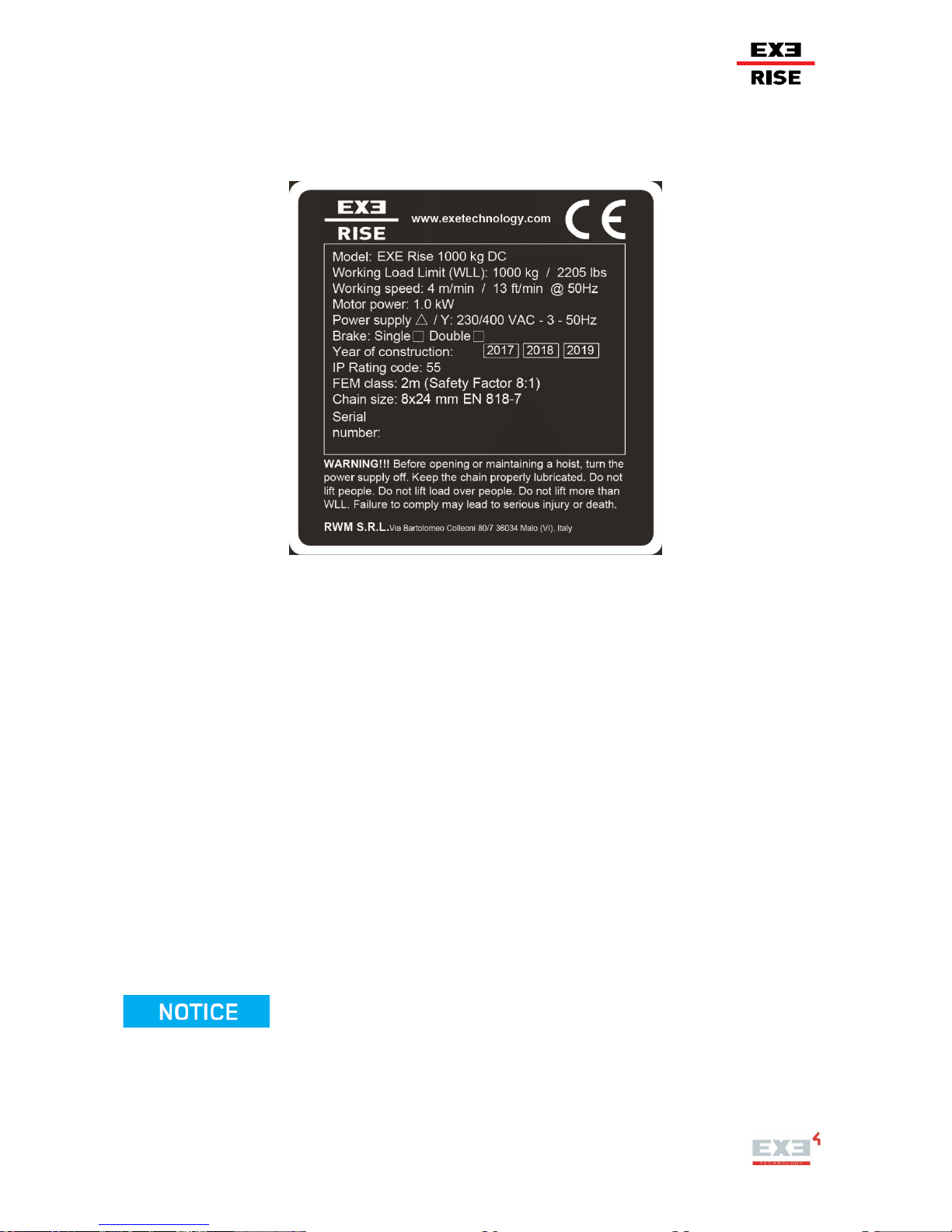
1.2 CHAIN HOIST IDENTIFICATION
EXE-Rise chain hoists are marked on the body by an aluminium plate visibly, legibly and indelibly with
dimensions 90x90 mm and thickness 0.8 mm.
Figure 1 “Example of EXE-Rise chain hoist plate”
The title of plate contains the business name and full address of the manufacturer, designation of the
machinery and website. The body of plate contains:
- Model: commercial name, model and type of machinery;
- Working Load Limit (WLL): the maximum working load designed by the manufacturer;
- Working speed: units of measure “m/min” and “ft/min”;
- Motor power: units of measure “kW”;
- Power supply: operating voltage;
- Brake: number of brakes;
- Years of construction;
- IP Rating code: International Protection Rating (first digit is the solid protection and second digit is the
liquids protection);
- FEM class: European Federation of Materials handling and safety Factor;
- Chain size: units of measure “mm” in according to EN DIN 818-7
- Serial number;
- Safety Factor (SF) and Double Brake: this information is included in a square;
- Warning: Before opening or maintaining a hoist, turn the power supply off. Keep the chain
properly lubricated. Do not lift people. Do not lift over people. Do not lift more than WLL
(Working Load Limit). Failure to comply may lead to serious injury or death.
The plate is in English language. In others languages, the translation is present only in this manual.

9 / 64
1.3 SAFETY SIGNAL
The present manual contains different safety signal to individuate and to point out precautionary statements.
The safety signals are sentences providing information on potential hazards, and proper procedures, as is
provided below:
DANGER: indicates a hazardous situation which, if not avoided, will result in death or serious injury. This
signal word is to be limited to the most extreme situations.
WARNING: indicates a hazardous situation which, if not avoided, could result in death or serious injury.
CAUTION: indicates a hazardous situation which, if not avoided, could result in minor or moderate injury.
NOTICE: address practices not related to personal injury.
SAFETY INSTRUCTIONS: is used to list steps, procedures or instructions that might otherwise constitute a
DANGER, WARNING or CAUTION notification. Note that equivalent phrases, such as SAFE OPERATION
PROCEDURES or SAFE SHUT DOWN PROCEDURE, can be used in place of the words “SAFETY
INSTRUCTIONS.“
1.4 TERMS AND DEFINITIONS
Operator: it is intended a person who, by virtue of training and professional experience, has a specific
competence in the field of safety and mechanical equipment and is familiar with the related national rules on
health protection and safety at work and with the rules of good technical practice (technical regulations
issued by the Country in which the hoist is used). The expert must be able to verify the safety and
mechanical equipment and give the related evaluation.
Maintenance: a combination of all technical and administrative actions, including supervision actions,
intended to maintain or restore an entity in a state where they can perform the required function.
Maintainer: personnel authorized to perform maintenance
Lifting Machinery: also known as lifting gear, is a general term for any equipment that can be used to lift
loads. This includes jacks, block and tackle, hoists, rotating screws, gantries, A frames, gin poles, shear legs,
sheerleg, windlasses, lifting harnesses, fork lifts, hydraulic lifting pads, air lift bags, and cranes.

10 / 64
1.5 REPAIRING – REPLACEMENT – WARRANTEE POLICY
REPAIRING AND REPLACEMENTE POLICY
The hoist has been checked and performance verified by RWM S.r.l. or one of its authorised service agents
before shipping.
If the correctly maintained hoist should present a performance problem due to faulty material or
workmanship, after inspection by RWM S.r.l. or authorised agent, repairing or replacement of the unit will be
made free of charge in favour of the original purchaser.
This repairing/replacement policy only applies to installed, under maintenance and operating Hoists, as
highlighted in this manual and does not include the parts subject to normal wear and tear, misuse, improper
installation, inadequate and incorrect maintenance, the effects of hostile environments and unauthorised
repairing/modifications.
The manufacturer and dealers cannot accept responsibility for any damage or lack of functionality due to the
following situations:
- carrying out inappropriate operations for an electric chain hoist;
- product modification without the express authorization of the manufacturer;
- inappropriate operation of the hoist;
- operational errors;
- failure to use the product as stated in the manual.
RWM S.R.L. DECLINES LIABILITY FOR ANY DAMAGES ARISING FROM A NON-COMPLIANT
INSTALLATION AND MAINTENANCE INDICATED IN THIS DOCUMENT.
WARRANTY POLICY
1. For a period of 12 month we undertake to repair, free of charge any damage attributable to faulty
materials or workmanship, provided that the appliance is forwarded, freight paid, to our works or one of
the EXE contract service organisations.
2. The guarantee-period begins with the day of the delivery, proven by a purchase receipt like an invoice
or delivery note or their copies.
3. The guarantee only is applicable for new equipment.
4. The guarantee does not cover damage due to transport damage, negligent handling, overload or parts
subject to normal wear and tear. Nor damages that originate from a case of misuse because of nonobservance the instructions in this manual.
5. Warrantee also does not include the cost to be made to get access to a hoist in case it is built in. It is
the users sole responsibility that hoist can be inspected and service in a normal manner and in places
accessible for persons and their equipment.
6. 6The fitting of replacement parts not supplied by us or modifications of our design by third parties also
invalidates the guarantee.
7. Guarantee repairs do not renew nor extend the guarantee-period.
8. In case of a claim under the guarantee, a malfunction or spare part requirements please contact your
point of sale or EXE
The complete chain hoist comes with a 12 month manufacturer’s limited warranty from the date of purchase.
A 24-month warranty covers the mechanicals parts excluding electrical and wear parts (brake disc, pendant
with cable, safety catch, plastic box, chain bag ).

11 / 64
WARRANTY LIMITATIONS, REMEDIES AND DAMAGES
This warranty does not apply where normal wear, abuse, improper or inadequate maintenance, eccentric or
side loading, overloading, chemical or abrasive actions, excessive heat, outdoor use without appropriate
measures or unauthorised modifications or repairs cause deterioration of the hoists. This warranty does not
apply to products which RWM S.r.l. has determined to have been misused or abused, connected to voltages
other than those recommended, improperly maintained by the user, or where the malfunction or defect can
be attributed to the use of non-genuine RWM S.r.l. parts.
This expressed warranty is in lieu of all other warranties, expressed or implied, of marketing, fitness for a
particular purpose, or in any other manner, no promise or assertion of fact declared by any vendor’s agent or
representative shall constitute a vendor’s warranty or shall determine any liability or obligation.
The vendor guarantees that at the delivery date to the forwarding agent the goods are free from defects in
workmanship and materials. The sole obligation of possible breach of the warranty or contract for negligence
or in any other manner concerning the goods sold, shall be exclusively limited to repair or replacement, f.o.b.
vendor’s shipping point of any part that the vendor determines to be faulty, or, should the vendor determine
that such repair or replacement cannot be undertaken, to a reimbursement of the purchase price upon return
of the goods to the vendor.
Any action against the vendor for breach of contract, negligence or others must be initiated within one year
from the occurrence of such trial action.
No claim for damages to the vendor for any defects of the goods shall be deemed valid or applicable without
the written notification of the purchaser if it is not received by the vendor within one year from the shipping
date.
The vendor is not liable for any damage, injury or loss due to improper use of the goods if, before such
damage, injury or loss, such goods are (1) damaged or used in an improper manner following the delivery of
the vendor to the forwarding agent (2), not serviced, inspected or used in compliance with the applicable
laws and vendor’s written instructions and advices; or (3) installed, repaired, tampered or modified without
compliance with such law, instructions or advices. Under no circumstance the vendor shall be liable for
accidental or consequential damages since these terms are defined in section 2-715 of the uniform
commercial code.
COMPENSATION AND USE UNDER SAFETY
The purchaser must follow and request his labour force to follow the provisions indicated in the instructions
and manuals supplied by the vendor, and must use them and request his labour force to follow such
instructions and manuals and take suitable care in the maintenance of such products. The purchaser must
not remove, or allow anyone to remove, any warning plates or instructions on the product. In the event of
personal injury or damages to property or the Company resulting from the use of the product, the Purchaser
must give a written notification of such injury or damage to the vendor within 48 hours.
The Purchaser must cooperate with the Vendor in the inquiries on such injury or damage and in defence of
any claim for damages.
If the Purchaser fails to follow this section or if the injuries or damages are caused, totally or partially, by the
Purchaser‘s non-observance of the federal or state laws on safety, the Purchaser must indemnify and keep
harmless the Vendor from any claim, loss or expense for injuries or damages connected to the use of the
product.
12 / 64
1.6 DOCUMENTATION
The manual is integral part of EXE-Rise chain hoist and it contains the following documents attached:
- Declaration of conformity of EXE-Rise chain hoist;
- Declaration of conformity of chain;
- Declaration of conformity of hook;
- Wiring Diagrams;
- Data sheet of EXE-Rise chain hoist.
These documents are an integral part of the manual and they are an integral part of the hoist.

13 / 64
2. SAFETY INFORMATION
2.1 GENERAL SAFETY WARNING
Indicated below are the structural and environmental requirements that must be checked by the user for
guaranteeing safe use of the hoist:
The user is responsible for the construction method used for the set-up structure, the related load
capacity and the conditions of the suspension points arranged in the place of use. In addition to the risk
evaluation and operating procedures, project documentation (calculation reports, drawings, etc.) related
to such aspects, must also be prepared.
The set-up structure and the related elements involved (hoist anchoring point, hoist and related
accessories and the load thereof) must be able to bear the imposed loads (during the use of the load)
with a suitable safety factor. In the overall analysis, the dynamic forces must also be considered.
Use of the hoist under conditions other than those described, can result in accidents that may cause injuries
and/or material damages.
Check that the electrical supply system to be used is adequate and conforms to local standards.
Supplementary to the manual, the local statutory regulations governing general accident prevention and
environmental protection are to be enforced.
It is the sole responsibility of the client to check with local authorities if the legislation used by EXE-Rise
chain hoist is acceptable in the country of use.
Do not allow anyone under 18 years of age to operate the chain hoist.
STAY ALERT! Watch what you are doing and use common sense. Do not use the hoist when you are tired,
distracted or under the influence of drugs, alcohol or medication which may diminished control.
The employer has a duty to ensure that the operator has skills and knowledge to understand the contents of
this manual.
2.2 SAFETY WARNING FOR USE AND MAINTENANCE
The hoist can be used only and exclusively by authorised and qualified operator.
The operational parameters of the electric chain hoist also encompass compliance with the predefined
operating, service and maintenance requirements laid down by the manufacturer.
Chain hoists may only be used when in an acceptable technical condition, in accordance with their operating
parameters, by trained personnel in a safe and responsible manner.

14 / 64
The hoist must be used with a control system that meets local electrical safety regulations.
The operational parameters do not allow, but are not limited to:
- exceeding the defined load capacity
- any lateral load to be applied the hoist body
- any side pull to be applied the lift chain
- heaving, pulling or dragging the load
- standing beneath suspended and/or lifted loads
- transporting excessive loads
- pulling on the control cable
- failing to observe the load hook constantly
- failing to observe the load constantly
- running the chain over edges
- slack chain to occur which may cause the load to fall
- use at temperatures below -10° C or above +40° C
- use in an explosive environment.
Bumping operations shall be limited; ground mooring and driving against the limit switches should be
avoided. The manufacturer accepts no responsibility for damage to equipment and third parties ensuing from
such action.
Special attention shall be taken when hoists are used in or near aggressive environments (e.g. Salt water or
chloroform ). The aluminum and steel alloys used might not be particularly suitable for such environments.
Special attention to protect the chain shall be taken. A high level of lubricant as well as a proper condition of
the zinc layer helps to prevent the chain from becoming corroded. Do not allow anyone under 18 years of
age to operate the chain hoist.In addition to the instructions mentioned in this manual, the user must follow
the rules on accident prevention and safety that are in force in the country where the hoist is being used.
Follow these operating instructions:
Only competent persons are permitted to use the equipment. Make sure you are adequately trained.
Know your load before lifting! Make sure all loads exposed are considered. For example but not limited
to; Self-weight of the load to be lifted, Self-weight of the lifting equipment, the dynamic factor caused
by start and stopping of the hoist, point of gravity of the load and environmental influences such as
wind.
When preparing to lift a load, be sure that the attachments to the hook are firmly seated in hook
saddle. Avoid off centre loading of any kind, especially loading on the point of the hook.
Before lifting, check for twists in the load chain. On single reeved chain hoist used in conjunction with
head blocks and ground support systems, check for twists between the hoist and head block. Twisted
load can result in a jammed chain and damage to the hoist.
On double reeved units a twist can occur if the lower hook block has been upturned between the
strands of chain. The hook should be reversed to remove the twist from the chain before operation.
A safe way of storage in order to avoid turns in the chain is to run the lift hook back to the hoist body,
or secure the hook to a fixing point within its transportation case.
Warn personnel of your intention to lift a load. Make sure the only noise in the area is that of running
hoist. This way abnormalities can be detected easier. Use spotters at required position in order to
observe the lift.
In the event of any abnormal sound coming from the hoist, lifting should be ceased immediately and
the noise investigated by a competent person.

15 / 64
Secure the load with a secondary device before entering the area beneath the suspended load . or
use D8+ hoist with EXE-Load cells. Depending on local legislation and the outcome of a risk
assessment the hoist may be left without these precautions.
Take up a slack load chain carefully and start load gently to avoid shock and jerking of the hoist weight
chain. If there is any evidence of overloading, immediately lower the load and remove the excess load.
When lifting, raise the load only enough to clear the floor or support and check all attachments to the
hook and load are firmly seated and secure. Continue to lift only after you are certain all attachments
are in good order and the load is free from any obstructions.
Arrange periodic maintenance to ensure the hoist is functioning correctly and in accordance with this
document.
In general, use of the hoist with materials, adjustments or modifications not envisaged in this
document strictly is prohibited
Maintenance shall be solely executed by RWM S.r.l. authorised persons.
Keep the hoist clean and efficient by carrying out the suggested maintenance program.
Avoid “bumping” of a hoist. With bumping is meant frequently pressing the start and stop button to
adjust the hoist position.
Do not load hoist beyond the rated capacity. Overload can cause failure of some load-carrying part or
create a defect causing subsequent failure at less than rated capacity.
Working inside or near powered equipment can result in electric shock: before carrying out any work on
the hoist, always disconnect power supply and make sure that no one can insert the plug again until the
task is complete.
When possible, maintenance must be carried out without suspended load; failing this, the area must be
enclosed and monitored and the load must be held by means of a secondary safety component.
Do not clean the hoist using a pressure washing device.
Keep maintenance and test reports issued by RWM S.r.l. together with the manual.
All maintenance, repair, adjustment, cleaning operations must be carried out only by qualified personnel
duly trained and competent, who has fully read and understood this document.
Maintenance must be carried out in a safe area whilst using proper tools and safety equipment.
In case of poor ambient lighting, install a lamp for local lighting for maintenance interventions or use
adequate portable devices.
Replace any cable or wire with like for like items.
Use only spare parts identical to those to be replaced or previously authorised by the manufacturer.
Follow industrial hygiene rules during cleaning of the machine.
In the instance of maintenance work being carried out at height, please ensure the correct access
equipment is employed, and local safety regulations are taken into consideration.
No makeshift repairs with the aid of extra pieces or taping are allowed. It is prohibited to warm
equipment with flames, hot air or other instruments in case they are stiffened or blocked.
Always wait for parts to cool if the hoist has been running intensively before maintenance.
2.3 SAFETY WARNING FOR INSTALLATION, ASSEMBLY AND DISASSEMBLY
The hoist must be assembled and disassembled only by authorized and qualified operator. The necessary
qualifications for planning, assembly, disassembly, and activation, depend on the degree of risk and the
location and type of job.
Operator are required to provide current overload protection and grounding on the branch circuit section in
keeping with the code. Check each installation for compliance with the application, operation and
maintenance sections of these articles.
16 / 64
This manual gives the necessary information for safe installation, use, and maintenance in a generic working
environment. Since it is not possible to foresee all the risk conditions of the working environments in which
the hoist will be used, the person responsible for the management and supervision of the installation,
assembly and disassembly must produce their own specific risk assessment each time the hoists are used.
The hoist must be tested only by authorised and qualified operator. The person in charge of management
and supervision is liable to give his approval to the use of electric chain hoists. Such approval can only be
given on condition that the occurred carrying out of the tests is duly proved. Every possible transfer to other
users must be documented in writing.
The hoist is equipped with various guards and devices designed to prevent accidents and to ensure the
product complies with various safety standards.
2.4 SAFETY WARNING FOR INCORRECT USE
Do not lift people. Using the EXE-Rise chain hoist to carry people is strictly forbidden.
Do not use the hoist if it is damaged, malfunctioning, or functioning in an unusual way or exhibits
unusual or incorrect movement or anomalous noises.
Do not use the hoist if the chain is distorted, corroded, damaged, or worn out.
Do not make modifications nor apply accessories other than those provided by RWM S.r.l..
Accessories causing overstressing or leading to accidental unexpected overloads or limiting the free
handling of the load, are not allowed. Therefore only lifting accessories that interpose in a passive way
between the equipment and the load are allowed.
Do not try to lengthen the lifting chain or repair it if damaged.
Do not hit, deform, or crush the hoist chain; danger of cracks or broken links may occur.
Do keep the hoist and chain away from open fire or flame.
Do not use the lifting chain as sling and do not wrap the chain around the load.
Do not put tools or foreign bodies in the links of the chain.
Do not place the load on the point or on the spring latch of the hook.
Do not perform welding to any component.
Do not use the hoist if it is not perfectly efficient, even if it can still function.
Do not use the hoist with worn out, open hook or with missing spring latch.
Do not lift loads exceeding the maximum working load limit of the hoist (In Motor-down mode the self-
weight of the hoist should be taken into consideration. The self-weight of the hoist should be added to
your payload calculations).
Do not allow the load to swing or twist while lifting.
Do not lift the load above people or do not leave hanging loads without the operator’s control and
appropriate measures.
Do not use the hoist outdoors or anywhere with water jets or environmental conditions without adequate
protection.
The use in explosive, aggressive atmosphere or with high concentration of powders or oily substances
suspended in the air is prohibited. Electrical devices produce arcs or sparks that can cause a fire or
explosion.
Do not operate hoist at unusual extremes of ambient temperatures. The product is designed for use in
temperatures ranging between -10°C and +40°C.
It is prohibited to tamper with the hoist in order to modify its performances.
17 / 64
Do not remove or tamper with the protective and safety devices
Use of the hoist is prohibited to unauthorised operators who are not adequately trained in use of the
hoist and the associated dangers.
Do not use of the hoist outside the limits indicated in this document.
Make sure the chain is running straight into the hoist body. Any side pull will cause significant wear
and tear on the hoist.
Do not apply a lateral load to the body of the hoist.
Make sure the pick-up points are always in-line with the hoist. Any side pull will cause an increase in
loading on both the hoist and the structure.
2.5 SAFETY WARNING FOR RESIDUAL RISKS
Residual risks related to a machine are accident risks that remain after the carrying out of all the safety
measures taken by the manufacturer (and which therefore must be managed by the user).
The most serious residual risks are indicated on the hoists safety labels. These are as listed below (Table 1).
Residual risk, dangerous zone
and person exposed
Course of action to eliminate or reduce risk
Malfunction or falling load due to
overload
Do not exceed the hoist load limit
Various types of risks owing to the
wrong installation and use of the
hoist.
Read the instructions before installing or using the hoist
Fall risk to people being lifted by
the hoist
It is prohibited to lift people by means of the hoist
Damage to hoist due to dry chain
Chain should be kept lubricated
Risks of structural collapse
Check structure is able to support the proposed load. Check all
components in the lifting system are suitably rated and able to bear
the proposed load
Risk of injury from malfunction hoist
or manoeuvre error
Working area should be managed and access controlled
Fall risks (of the installer or
serviceman) from the load or
structure
Appropriate PPE should always be used. Climbing the load or
structures should be avoided if possible. When possible carry out all
maintenance at ground level
Various types of risks owing to the
illegibility of the labels
Do not remove or cover labels
Various types of risks owing to the
lack in periodical maintenance
Check that the annual periodical maintenance has been carried out.
Various types of risks when used in
severe weather conditions
Check the environment conditions before using the hoist.
Malfunctioning risks owing to wrong
power supply
Make sure that the power supply is the same as indicated on the
chain hoist plate.
Chain fall due to damaged chain
bag
Check bag for damage before use. Do not fill bag over 75%
capacity
Various types of risks owing to
(electrocution, malfunctioning, etc.)
non-sectioning before any
maintenance intervention.
Before any maintenance intervention, disconnect the power supply
from the hoist. Maintenance operations can be carried out only by
competent and authorised persons.
18 / 64
Residual risk, dangerous zone
and person exposed
Course of action to eliminate or reduce risk
Sudden start owing to the insertion
of the plug into a normal socket.
Do not insert the hoist power plug directly into a CEE socket. The
hoist may only be powered using suitable control devices, such as
EXE-DRIVE controllers. For low voltage controlled hoists, a
dedicated controller must be used with an UP/DOWN push-button
panel that complies with the wiring diagram provided.
Various types of risks owing to
tampering or removal of the safety
devices.
It is prohibited to tamper or remove the safety devices
Table 1: “Residual risks”
2.6 SAFETY WARNING FOR ELETRICAL CONNECTION
Before a hoist is connected to its control device the power supply shall be checked for correct voltage.
A fluctuation of +/- 10% is allowed. In order to prevent a voltage drop, the user should ensure there is the
minimum number of connections as possible in any power cable run.
Keep length of power cables as short as possible (see table below) and remove corrosion on the contacting
pins of the electrical connectors as it might lead to a voltage drop.
In order to minimize the voltage drop between the power source and the hoist the following cable lengths
shall be used as maximum (see Table 2).
Model
(*)
Capacity
Capacity
1,5 mm 2 wiring
2,5 mm 2 wiring
kilogram
Pounds
400V/50Hz
230V/50Hz
400V/50hz
230V/50Hz
SF-8
250
kg
551
lbs
250 m 820
ft
75 m 246
ft
255 m 837
ft
80 m 262
ft
SF-8
500
kg
1102
lbs
100 m 328
ft
40 m 131
ft
110 m 361
ft
45 m 148
ft
SF-8
1000
kg
2205
lbs
65 m 213
ft
25 m 82
ft
75 m 246
ft
25 m 82
ft
SF-8
2000
kg
4409
lbs
65 m 213
ft
25 m 82
ft
75 m 246
ft
25 m 82
ft
D8+
150
kg
331
lbs
250 m 820
ft
75 m 246
ft
255 m 837
ft
80 m 262
ft
D8+
300
kg
661
lbs
100 m 328
ft
40 m 131
ft
110 m 361
ft
45 m 148
ft
D8+
600
kg
1323
lbs
65 m 213
ft
25 m 82
ft
75 m 246
ft
25 m 82
ft
D8+
1200
kg
2646
lbs
65 m 213
ft
25 m 82
ft
75 m 246
ft
25 m 82
ft
(*)
EXE-Rise Models are explained in paragraph 3.2
Table 2 “Relation between power and lengths of cable”
The electrical power plug must be disconnected from the power supply of the hoist in case of maintenance or
emergency.
Dangerous voltage drop can be caused by using excessively long extension cables as well as by
overheating the wire.
19 / 64
3. EXE-Rise CHAIN HOIST INFORMATION
The intended use of EXE-Rise chain hoist is to vertically lift loads or hold loads once lifted within the rated
capacity of the model selected. They can be installed either as a fixed device or can be mobile.
3.1 GENERAL DESCRIPTION
The EXE-Rise chain hoist are designed for installation of structures aimed at realizing events.
Events include elements such as concerts, shows, conferences, meetings, exhibitions,
presentations, demonstrations, television or film shoots and the like. The position of these events
include, among other places, theaters, multipurpose halls, studios, film sets, television and radio
broadcasts, concert halls, convention centers, schools, exhibitions, fairs, museums, clubs,
recreational parks, sports facilities, outdoor theaters and meetings.
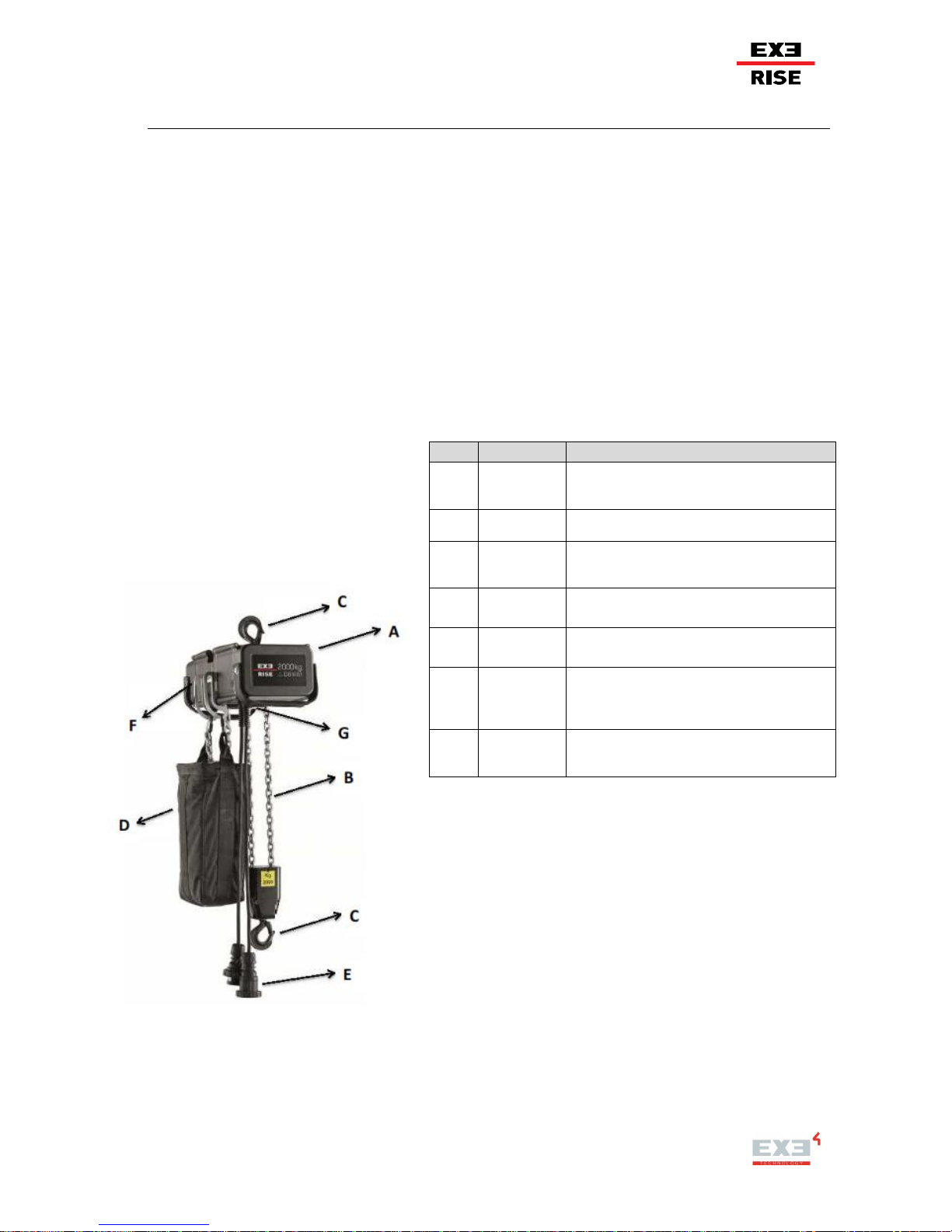
The EXE-Rise chain hoist consists in several parts. In Figure 2 and in Table 3 are reported main of these.
Table 3 “EXE-Rise chain hoist parts”
Figure 2 “EXE-Rise chain hoist parts”
COD
TITLE
DESCRIPTION
A
BODY
The body s made in cast aluminium to be as
light, yet as strong as possible. The matt black
finish is corrosion resistant and non-reflective.
B
CHAIN
The chain is in Zinc Galvanized, with grade of
steel equal to 80.
C
HOOK
The hook is in Carbon Steel and they are
equipped with a sprung safety latch that prevents
accidental release of loads
D
CHAIN
BAG
The chain bag is in Polyvinyl chloride coated
65% PVC (Nylon 840), 35% Polyamide.
E
PLUG and
SOCKET
The plug and socket are produced from
Polyamide 6 as well as PC7ABSm (IP66/67)
F
BRACKET
The chain-bag bracket in aluminum and the
design ensures the bag is positioned correctly to
accept chain without the need for any
adjustment.
G
GUIDE
PLATE
The chain guide plate is made in PVC to
prevent breaking the chain guide if the chain
jams(Small body hoists use steel guide plate.
20 / 64
3.2 IDENTIFICATION
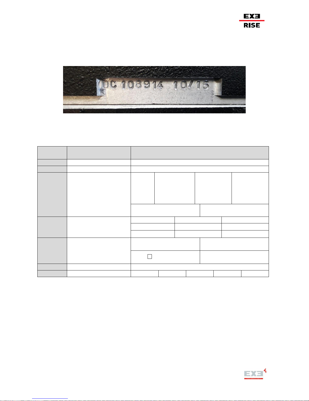
The chain hoist EXE-Rise are uniquely identified by a serial number carved on the hoist body. The
manufacturer RWM marked years of construction too.
Figure 3 “EXE-Rise chain hoist serial number”
Accordance with the procedure that RWM Srl has established, EXE-RISE hoists are encoded as follows:
XRH + A + B + CCC+ DDD+ EE + F
CODE
FORMAT
DESCRIPTION
TYPE
XRH
EXE-Rise chain Hoist
----
A
version hoist number
1 – 2 – 3 – 4 – 5 – 6 – 7 – 8 ….
B
type of control and limit
switch size
D=Direct
Control
L= Low Voltage
Control - limit
switch 50 m
M= Low
Voltage
Control - limit
switch 30 m
N= Low
Voltage
Control - limit
switch 30 m RWM
N= Low Voltage Control -
limit switch 75 m
V=EXE-Vario 20 m/min
CCC
load capacity/10
015 =150 kg
025=250 kg
030 =300 kg
050 =500 kg
060 =600 kg
080=800kg
100 =1000 kg
120 =1200 kg
200 =2000 kg
DDD
model hoist
S8- = D8 SF 8:1
D8- = D8 SF 5:1- 1 brake
D8+ = D8+ SF 10:1
DB- = D8 SF 5:1- 2 brake
EE
chain length in meter
max length = 100 m / 220 lbs
F
chain bag size
XS S M L X (XL)
Table 4 “EXE-Rise chain hoist identification”
For example LT XRH1D100DB-20M is EXE-Rise chain hoist D8 bouble brake direct control with WLL
1000kg, chain bag size M and with 20m of chain.

21 / 64
3.2.1 Model
EXE-Rise Chain hoist models are based on a German standard that differentiates between three types of
electric chain hoists:
D8 Hoist
Electric chain hoist according to DGUV 115 (formerly known as BGV D8) "Winches, lifting and pulling
devices") for use as a chain hoist for lifting loads in construction.
D8 Plus Hoist
Electric chain hoist based on DGUV 115 "Winches, lifting and pulling devices" for use as a chain hoist for
lifting loads in construction with the special characteristic of being able to hold loads statically above people
without the use of secondary safety devices. The types of electric chain hoists specified above can be
operated both individually and in groups. The choice of the type of electric chain hoist depends on the
operating conditions:
D8
D8 with
secondary safety device
D8 Plus**
With people under the load
Holding loads
not permitted
permitted
permitted
Erection /dismantling,
rigging operations
not permitted
not permitted
not permitted
Scenic movement
not permitted
not permitted
not permitted
Complex scenic
movement
not permitted
not permitted
not permitted
Table 5 “Selection criteria for electric chain hoists for moving and holding loads above people”
Local legislation shall be checked for specific regulations. For guidance we refer to the German regulation
DGUV 17 (formerly known as BGV) The user could refer to German SQ-P2 code-of-practice for information,
which can be obtained at www.igww.org
* Source: IGVW SQ P2 – Electric chain hoists
** For statically indeterminate loads, Load cells shall be used in combination with hoist control. The lifting operation shall be stopped in
the event of exceeding the pre-set over- or underload – limits. Values shall be derived from structural analysis of the applied loads
3.2.2 Type of Control
Selection of the hoist also depends on the duty class needed. The duty class refers to the time the hoist can
operate under full load. EXE-Rise chain hoists have a minimum rating of 1Bm and maximum rating of 2m as
per FEM classification; See table 6.
Class
1Bm
1Am
2m
3m
Duty factor of motor
25%
30%
40%
50%
Starts per hour
150
180
240
300
Table 6 “FEM Classification”
Depending on its operating hours and the load applied the same hoist can also be used in another duty
class. Please contact RWM for support if this is required. Table 7 gives guidance for correct selection

22 / 64
Load spectrum
Average operating time per day in hours
≤0.25
≤0.5
≤1
≤2
≤4
≤8
≤16
Light
1Bm
1Am
2m
3m
Moderate
1Bm
1Am
2m
3m Heavy
1Bm
1Am
2m
3m
Very Heavy
1Bm
1Am
2m
3m
Table 7 “Average operating time per day in hours”
Direct control hoists
The terms direct control (DC) and low-voltage controlled (LVC) refer to the system used to manage hoist
movement, not to the power supply voltage.
With DC hoists, the travel direction is determined directly by the phase sequence of the three phase power
supplied to the red CEE plug fitted (CEE 16A 6h 400 VAC – 3PH). Phase reversing contactors are inside the
controller and not inside the hoist. The hoist lifts when the three power phases are in normal sequence and
lowers when they are inverted.
DC hoists have an integrated mechanical emergency overload device known as the slip clutch. This slip
clutch is adjustable but changes to this device must only be performed by an officially trained and competent
person. A chain stop (a two part metal block) is attached to the end of the load chain, 11 links form the end,
which prevents the chain from running through the hoist should it overrun the length of the chain.
The chain stop shall be placed 11 links from the end. This gives the user or person carrying out any
inspection, access an unloaded length of chain as measuring reference compared to rest of the chain which
will have been under load.
Low Voltage Controlled hoist
LVC hoists are fitted with a CEE plug (CEE 16A 6h 400 VAC – 3PH) for three phase power and a yellow
CEE plug (CEE 16A 4h 24 VAC – 3PH) for control purposes. The direction signal is given by a low voltage
hoist controller and is transmitted along the control cable which activates reversing contactors inside the
hoist body. LVC hoists have an integrated mechanical emergency overload device known as the slip clutch.
This slip clutch is adjustable but changes to this device must only be performed by an officially trained and
competent person.
LVC hoists also have an integrated adjustable electrical limit switch that halts the lifting and lowering
operation at pre-set positions. The control signal is a 24 VAC low voltage circuit.
These electrical limit switches can be set to limit the chain travel during both lifting and lowering operations.
The factory default settings can be adjusted by altering the position of the “up” and “down” cams. The limit
switches are factory calibrated in such a way as to stop the motor automatically a few links before the chain
comes to an end in both directions.
After setting the up/down selector, press the start button on the control unit to which the EXE-Rise LVC hoist
has been connected. When the external up / down button is selected the control signal activates the
contactor inside the hoists and powers the motor, setting the chain in motion in the required direction. The
23 / 64
chain will continue to travel through the hoist in the chosen direction until it reaches a mechanical stop on the
chain, or until the electrical limit switch reaches its pre-set end point. Once the limit switch is activated the
hoist can only be run by reversing the direction of travel.
Any control unit used to power EXE-Rise LVC hoists must provide an "un-inverted" three phase power
supply. An incorrect sequence of phases make the hoist run in a different direction as the limit switch. This
will result in damage of the limit switches and potential over run of the chain.
Electric chain hoists are offered in a variety of designs and feature options; as well as with different safety
devices. This means that the choice of chain hoist is extremely important. Consideration must be given to
risks arising from the nature of the intended operational use and the specific operating conditions.
The selection must be based on the hazards arising from the type of use, taking into account the specific
conditions of use whilst abiding to the local laws in the country of use. We strongly advise that the
user/operator carries out a risk assessment on which the choice of your hoist shall be based.
3.3 COMPONENTS DESCRIPTION
Every single component of the EXE-Rise hoist body is manufactured in Italy. The high grade Lifting chain is
coming from Germany and complies with the strictest EN and DIN standards relating to lifting in the
entertainment industry. The EXE-Rise clutch system is located outside the load path. The DC brakes give a
real instant response to electrical impulses thanks to a unique component specifically created for us. The 5pocket load wheel, helical gears with dynamic lubrication and the precise aluminum chain guide make
the EXE-Rise series one of the quietest on the market.
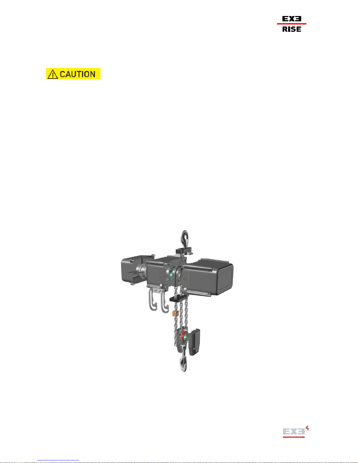
Figure 4 “EXE-Rise chain hoist 2000 kg DC principal components”
24 / 64
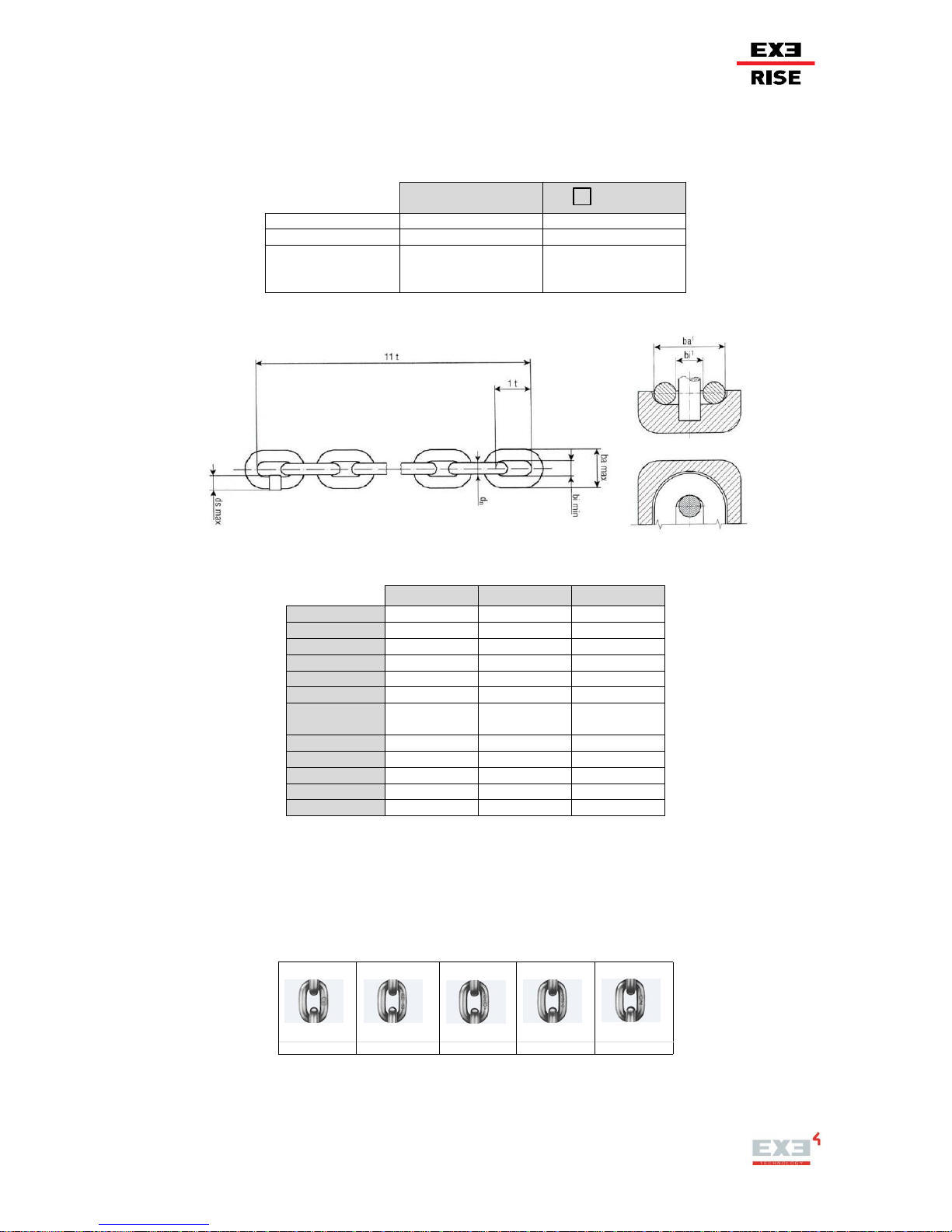
3.3.1 Chain
The chain used for EXE-Rise chain hoist is in Zinc Galvanized Steel EN DIN 818-7 (grade of steel: 80).
There are five measures in order to hoist chain of destination:
CHAIN
SF-8
D8+
4x12 mm
D8 250 kg
D8+ 150 kg
6x18 mm
D8 500 kg
D8+ 300 kg
8x24 mm
D8 1000 kg
D8 2000 kg
D8+ 600 kg
D8+ 800 kg
D8+ 1200 kg
Table 8 “Chain measures”
Figure 5 “Chain dimensions”
Each chain has specific characteristics, among them the most important are reported:
Table 9 “Chain technical data”
LEGEND:
dn: nominal diameter – 1t: nominal pitch – bi
min
: minimum inner width – ba
max
: maximum outside width – Gauge length: 11t (11 links) –
ds
max
:maximum welding diameter – σ
min
: minimum stress at breaking force – F
min
: Minimum Breaking Force (MBF) – A
min
:minimum total
ultimate elongation – WLL: max Working Load Limit.
Chain can be identified from the manufacturers stamped identification marks on the chain. The stamps
shown are repeated at regular intervals along the length of the chain.
Figure 6 “Chain identification”
Permittance stamp Grade Type Manufacturing no. Batch no.
CHAIN 4x12
CHAIN 6x18
CHAIN 8x24
Code
XRC032-01M
XRC0618-01M
XRC0618-01M
Weight
0.35
0.78
1.39
dn [mm]
4.0
6.0
8.0
1t [mm]
12.0
18.0
24.0
bi
min
[mm]
5.0
7.2
9.6
ba
max
[mm]
13.7
20.2
27.0
Gauge length
[mm]
132.0
198.0
264.0
ds
max
[mm]
4.3
6.5
8.6
σ
min
[N/mm2]
800
800
800
F
min
[kN]
20.1
45.2
80.4
A
min
10 %
10 %
10 %
WLL [kg]
320
720
1280

25 / 64
3.3.2 Hook
The hooks are forget Carbon Steel or Alloy Steel with heat treatment in according to Machinery Directive.
Small body hoists use Stainless Steel.
CHAIN SWIVEL HOOK
D8 250 kg and D8+ 150 kg - D8 500 kg and D8+ 300 kg
Figure 7. “Lift chain hook with safety latch” D8 250 kg and D8+ 150 kg - D8 500 kg and D8+ 300 kg
D8 1000 kg and D8+ 600 kg
Figure 8. “Lift chain hook with safety latch” D8 1000 kg and D8+ 600 kg
DIMENSIONS [ mm ]
A B D G H L O
73
51
15
16
20
64
18
DIMENSIONS [ mm ]
A B D G H L O
92
64
20
21
27
72
30

26 / 64
D8 2000 kg and D8+ 1200 kg
Figure 9. “Lift chain hook with safety latch” D8 2000 kg and D8+ 1200 kg
The standard ingress protection Level of IP55 means that when the hoist is used in wet environments,
adequate protection of the hoist body is required.
BODY SWIVEL HOOK
Body swivel hook is an assemblage of a plate with two holes, two fixing screws and hook (see Chain Swivel
Hook for models).
Figure 10. “Example of Body Swivel Hook”
EXE-Rise chain hoists with a lifting speed up to 8m/min generate a dynamic factor of 1.2 during start and
stop. Tolerances in lifting speed up to 5% can occur within same models of the same manufacture. Lifting
speeds vary depending on the load, and if the load is lifted or lowered.
DIMENSIONS [ mm ]
A B D G H L O
122
82
30
28
36
97
33

27 / 64
3.3.3 Chain Bag Bracket
The chain-bag bracket allows the hoist to be used motor up or down. The design ensures the bag is
positioned correctly to accept chain without the need for any adjustment, reducing the chance of chain spills.
3.3.4 Chain Stop
Fits below dead end link on lifting chain for added measure of safety.
Table 10 “Chain stop code”
Figure 11 “Chain stop”
3.3.5 Quick Link
CONNECTION INSTEAD OF BRACKET
Chain bags shall be suspended by Quicklinks or Carabiners made according to DIN 56927 or equivalent
standard. Some bags are supplied with a suitable rated captive spring hook. Only rated hooks supplied by
RWM should be used.
CONNECTION INSTEAD OF BRACKET
Litec Code
Chain size
[mm]
XRSFC412
4x12
XRSFC515
6x18
XRSFC722
8x24
Litec Code
CHB004
Commercial name
Quick link
Description
Material: Zinc Galvanized
Carbon Steel
Color: black
Diameter: 6 mm
DIN
DIN 56927
SWL (Safe Working Load)
250 kg
Safety Factor
10:1
Weight
47 g
Table 11 “Chain bag – bracket Quick Link
technical data”
Figure 12 “Chain bag – bracket
Quick Link dimension”

28 / 64
Manufactured according to BGV C-1. It has a compact shape, is galvanized and stamped with the DIN
standard, manufacturer´s name and the carrying capacity.
Figure 13 “End chain – bracket Quick Link dimension”
Table 12 “End chain – bracket Quick Link technical data”
3.3.6 External Chain Guide Plate
The External Chain Guide Plate is made from a special PVC is used to minimize the chance of chain
jamming should the chain become twisted. This sacrificial plate helps protect both the chain and internal
chain guides. (Small body hoists use steel guide plate).
Figure 14 “External Chain Guide Plate”
Litec Code
Chain size [mm]
WLL
d c e l h b weight
[kg]
[mm]
[mm]
[mm]
[mm]
[mm]
[mm]
[g]
CHB037
6x18
7x22
8x24
140
5.0
3.0
22.0
52.0
13.0
13.0
25
CHB041
4x12
50
3.5 - -
29.0
10 5 9
CHB041
5x15
90
4.0 - -
32.0
11 5 13

29 / 64
3.3.7 Plugs and Socket
Plugs and sockets are produced from POLYAMIDE 6 as well as PC/ABS.
The main characteristics of these
materials are:
- excellent impact resistance combined with high rigidity and solidity,
- high thermal stability (self-extinguishing),
- very good insulating qualities,
- high disruptive strength,
- high abrasion resistance,
- high weathering resistance,
- very good chemical resistance to various chemicals,
- free from cadmium and halogen (fluorine, chlorine, bromine, jodine,
astatine),
- black color.
Figure 15 “Plug and socket”
3.3.8 Brake
The spring-applied brake is a single-disk brake with two friction surfaces. Several compression springs
create the braking torque by friction locking. The brake is released electromagnetically.
Figure 16 “Double brake version”
The spring-applied brake is designed for the conversion of mechanical work and kinetic energy into heat. For
operating speed. Due to the static brake torque, the brake can hold loads without speed difference.
Emergency braking is possible at high speed. The more friction work, the higher the wear.
Figure 17 “Brake Features”

30 / 64
EXE-Rise chain
hoist
D8 250 kg
D8+ 150 kg
D8 500 kg
D8+ 300 kg
D8 1000 kg
D8+ 600kg
D8 2000 kg
D8+ 800 kg - 1200 kg
DC Brake Size
06
08
10
DC Brake Power
20W
25W
30W
DC Brake
Operating Voltage
105VDC
105VDC
105VDC
DC Brake Rated
Torque
4Nm
8Nm
16Nm
DC Brake Rated
Torque Reduction
at the speed
specified x%
(1500r/min)
87% (1500 r/min)
85% (1500 r/min)
83% (1500 r/min)
Table 13 “Brake technical data”
3.3.9 Limit switch
Limit switch consists of 4 cams and a gear motor that transfers movement through a primary input reduction
stage (worm gear and helical toothed gear) and one or more secondary output stages (pairs of straight
toothed gears).
Figure 18 “Limit Switch large medium and body”
3.3.10 Chain Bag
Chain Bag used for EXE-RISE chain hoist is in Polyvinyl chloride coated polyamide 65% PVC (Nylon 840),
35% Polyamide. There are five size (XS, S, M, L, XL) in order to hoist chain of destination.
Table 14 “Chain bag characteristic”
Description
Nylontex 840 P.V.C. flame ritardent + PP BELT
Material
Polyvinyl chloride coated polyamide 65% PVC (Nylon
840), 35% Polyamide +
PP Yanr Multifilament 100% (Melting Points ≈ 165°)
Color
Black
Classification
Reaction to fire classification: E
combustible not inflammable - partially fire retardant.
Conformity to EN 119925-2
Safely Factor
5:1

31 / 64
Figure 19 “Chain bag”
Table 15 “Chain bag dimensions”
Table 16 “Chain bag size”
3.3.11 Bolts and nuts
All bolts and nuts used in the line of forces, shall be fastened by means
of a torque wrench. Grade 8.8 bolts are used and the following torque
shall be applied.
Table 17 “Bolts”
SPECIFICATIONS
CHAIN BAG XS
CHAIN BAG S
CHAIN BAG M
CHAIN BAG L
CHAIN BAG XL
Litec Code
CHB029
CHB024
CHB025
CHB026
CHB027
External
Dimensions [cm]
14x9
20x17
20x17
20x17
27x21
Height [cm]
40
34
42
58
65
Selfweight [kg]
≈ 0.75
≈ 1.00
≈ 1.00
≈ 1.00
≈ 1.00
CHAIN
Up to 26m
@75%
(26-40)m
@75%
From to 40m
@75%
4X12
XS
XS
-
6X18 S M
L
8X24 M L
XL
8.8 bolts
Lbsft
Nm
M4 2 3
M5
4,5 6 M6
7,5
10
M8
18
25
M16
159
215

32 / 64
3.3.12 EXE-Rise Chain Hoist Controllers
More EXE-Rise Chain hoists shall be operated by controllers designed and specified for this purpose. We
advise to use the EXE-DRIVE range controllers for proper use of your EXE-Rise chain hoist.
The use of other brands, in alternative to EXE-DRIVE controllers is not recommended unless they comply
with the applicable directives and standards. The controller shall provide the required control and monitoring
functions for save operation. The control system must meet the requirements of:
1. EN 60204-32: 2008 Safety of machinery - Electrical equipment of machines - Part 32: Requirements for
hoisting machines (IEC 60204-32: 2008);
2. 2006/42 / EC - Machinery Directive;
3. 2014/30 / EC - Electromagnetic Compatibility (EMC) Directive.
Controllers shall be chosen depending on the power consumption of an individual hoist, which can vary, as
well as its model (direct control or Low voltage control) or the amount of hoist one would like to control at the
same time.
We strongly advise to keep good view on the load being lifted. Using more than two hoist on one load
requires much more attention. Based on a risk analysis the user shall identify if the hoist and controllers need
additional control options such as Load cells, encoders etc...
In case the controller is equipped with Molded Case Circuit Breakers (MCCB), make sure the correct setting
of amperage is applied and the correct MCCB.

33 / 64
3.4 SAFETY DEVICE
The hoist is equipped with various guards and devices designed to prevent accidents and to ensure the
product complies with various safety standards.
3.4.1 Primary Safety Component
The guards and devices listed below must not be removed by the user. Before operation the user should
ensure all guards and devices are present, correctly fitted and have correct setting.
Removal of these guards and safety devices should only be allowed during maintenance by competent and
authorised persons and in controlled conditions.
Chain guide plate
EXE Rise chain hoists are fitted with a special plastic chain guide plate that provides various safety
functions.
- Prevents accidental contact with the internal moving parts.
- Prevents accidental contact with the internal parts that could reach high temperatures.
- Prevents wear between the chain and internal chain guide.
- Prevents jamming of the chain.
- Helps to reduce the chance of twisted chain entering the hoist.
These chain guides are a consumable item and should be replaced if they become worn.
Badly worn plates can be a sign of misuse. Eg. Side loading of the chain.
Hooks
The hooks are equipped with a sprung safety latch that prevents accidental release of loads when applied
correctly to the hook.
If this spring latch does not engage against the point of the hook correctly, or can fall through the opening of
the hook, the hook has overloaded and shall be replaced.
An unloaded hook attached to a lifting point can disengage itself when put under tension.
Therefore the hook shall be held under tension manually until loaded
Slip Clutch
The Slip clutch is designed and set up to act in the case of excessive load and therefore only shall be
considered as an emergency overload device. If overloaded, it starts to slip and the hoist will not lift.
The slip clutch shall never be used as a lifting height limiter.
If the clutch is subject to prolonged slipping it can overheat and become damaged. The clutch should not be
allowed to slip continuously for several seconds.
Considering the above statements, these hoists should not be used in an application where a suspended
load can be increased by adding additional weight. For example food lifts etc.

34 / 64
Figure 20: Example of securing a load
suspended from a tower by means of a
locking bar
Figure 21: Example of a secondary safety
component attached directly to the load that is
being lifted (front view)
Figure 22: Example of a secondary
safety component attached directly to
the load that is being lifted
3.4.2 Secondary Safety Component
A secondary safety component is a second independent suspension element of equivalent capacity to the
primary suspension point, which is intended to prevent the fall of the load should the primary point fail. Some
application examples are illustrated here below.
When operating a system according to the German DGUV V54 standard, or if maintenance is required on a
hoist that is still suspended, a secondary safety device should be used.

35 / 64
Figure 23: Example of a secondary safety
component attached below the hoist, bypassing
the hoist lifting mechanism (front view)
Figure 24: Example of a secondary
safety component attached below
the hoist, bypassing the hoist lifting
mechanism (perspective view)
Never use a chain clutch to connect the hoists lifting chain to a safety device. A lateral load to the lifting chain
can easily lead to failure.
3.4.3 Safety Conditions
Environmental conditions
To ensure the hoists function correctly, the following environmental conditions shall be observed:
Temperature
Temperature ranging between -10°C and +40°C
Humidity
The relative humidity must not be higher than 50% with maximum temperature of
+40°C. A higher relative humidity is allowed al lower temperatures (ex. RH. 90% AT
20°C).
Altitude
Maximum altitude at 3000m
Electromagnetic
environment
The hoist is designed to work correctly in an industrial type electromagnetic
environment, falling within the emission and immunity limits provided by the
harmonized rules currently in force
Wind
Wind can have a significant influence on the load suspended. The exposed influence
shall be considered at all time
Lighting of work place
During the set-up, dismantling and maintenance, it is favourable that the diffusion intensity does not have a
value lower than 300 lux. In case of use in environments with poor lighting (typical of the entertainment
sector), the localised lighting of the control devices and the intervention area must be arranged.

36 / 64
3.5 TECHNICAL DATA
- 4 x 1.5 mm2 power cable fitted with CEE 16A 6h 400VAC – 3PH +G black plug.
- 4 x 1.5 mm2 control cable fitted with CEE 16A 4h 24VAC – 3PH +G black plug (LVC only).
- Internal 25VA transformer: 400VAC on the primary windings, and 24VAC on the secondary
windings.
- Delay fuse 100 mA (0.1 A) on the primary windings, and rapid fuse 1 A on the secondary windings.
- Three-pole Schneider Electric series LC2-K09 reversing contactors with 24 V AC coil for a rated
power of 4 kW (AC3/400V).
- Mechanical limit switch 4 position with manual cam adjustment.
- Maximum control (Low Voltage Control) cable length attachable to motor: 50 m.
- Maximum chain length managed by low voltage control hoist: 60 m for single fall models and 30 m
for double fall models.
Other voltages and frequency are available on request.
For fully markets the chain hoist configuration available is 208VAC - 3 @ 60Hz. Custom configuration are
also possible, please refer to your local EXE TECHNOLOGY representative for all information.
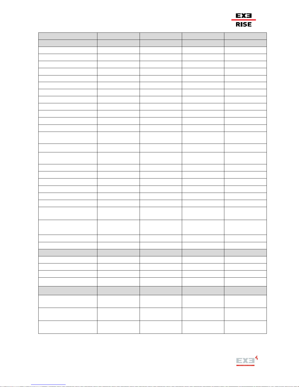
37 / 64
MODEL D8 DC / LVC
D8 250kg
D8 500kg
D8 1000kg
D8 2000kg
Hoist Specifications
Hoist Specifications
Hoist Specifications
Hoist Specifications
Hoist Specifications
Working Load Limit (WLL)
250kg
500kg
1000kg
2000kg
Lifting Speed @50Hz
4m/min
4 m/min
4m/min
4 m/min
Motor Power
0.5 kW
0.8 kW
1.0 kW
1.6 kW
Operating Voltage Δ / Y
230/400VAC - 3 - 50 Hz
230/400VAC - 3 - 50Hz
230/400VAC - 3 - 50Hz
230/400VAC - 3 - 50Hz
3 ph Δ 230 VAC Y 400 VAC
Δ 2.70A – Y 1.56A
Δ 3.93 A – Y 2.27 A
Δ 4.62 A – Y 2.67 A
Δ 8.37 A – Y 4.83 A
Falls of Chain
1 1 1
2
Load Wheel
5 pockets
5 pockets
5 pockets
5 pockets
Protection Class
IP55 DIN 40050
IP55 DIN 40050
IP55 DIN 40050
IP55 DIN 40050
FEM Classification
2m
2m
2m
2m
Duty Factor of Motor
40%
40%
40%
40%
Starts Per Hour
240
240
240
240
Connection Cable Lenght
1m
1m
1m
1m
Δ Power Supply Connector (*)
CEE 16A 9h 230VAC –
3PH + G black plug
CEE 16A 9h 230VAC –
3PH + G black plug
CEE 16A 9h 230VAC –
3PH + G black plug
CEE 16A 9h 230VAC –
3PH + G black plug
Y Power Supply Connector
CEE 16A 6h 400VAC –
3PH + G black plug
CEE 16A 6h 400VAC –
3PH + G black plug
CEE 16A 6h 400VAC –
3PH + G black plug
CEE 16A 6h 400VAC –
3PH + G black plug
Control Supply Connector
(only LVC)
CEE 16A 4h 24VAC –
3PH + G yellow socket
CEE 16A 4h 24VAC –
3PH + G yellow socket
CEE 16A 4h 24VAC –
3PH + G yellow socket
CEE 16A 4h 24VAC –
3PH + G yellow socket
Noise Level
67.5 db @ full load
67.5 db @ full load
67.5 db @ full load
67.5 db @ full load
DC Brake System
2 2 2
2
DC Brake Size
06
06
08
10
DC Brake Power
20W
20W
25W
30W
DC Brake Operating Voltage
105VDC
105VDC
105VDC
105VDC
DC Brake Rated Torque
4Nm
4Nm
8Nm
16Nm
DC Brake Rated Torque
Reduction at the speed
specified x% (1500r/min)
87% (1500 r/min)
87% (1500 r/min)
85% (1500 r/min)
83% (1500 r/min)
Clutch Characteristics
Clutch is friction based
force-limiter. Clutch outside
the line of kinetic
movement.
Clutch is friction based
force-limiter. Clutch outside
the line of kinetic
movement.
Clutch is friction based
force-limiter. Clutch outside
the line of kinetic
movement.
Clutch is friction based
force-limiter. Clutch outside
the line of kinetic
movement.
Limit Switch (only LVC)
Not Provided
2/4
2/4
2/4
Selfweight
≈ 17.0kg
≈ 24.0kg
≈ 43.0kg
≈ 45.0kg
Chain Specifications
Chain Specifications
Chain Specifications
Chain Specifications
Chain Specifications
Size
4x12mm
6x18mm
8x24mm
8x24mm
Safety Factor
8:1
8:1
8:1
8:1
Selfweight
0.35kg/m
0.78kg/m
1.39kg/m
1.39kg/m
Material
Zinc Galvanized Steel
grade 80
Zinc Galvanized Steel
grade 80
Zinc Galvanized Steel
grade 80
Zinc Galvanized Steel
grade 80
Chain Bag Specifications
Chain Bag
Specifications
Chain Bag
Specifications
Chain Bag
Specifications
Chain Bag
Specifications
(Chain Length Up to 26m) Size Selfweight - External dimension
- Height
XS - 0,75kg 140x90mm - 400mm
S - 1,00kg 200x170mm - 340mm
M - 1,00kg 200x170mm - 420mm
M - 1,00kg 200x170mm - 420mm
(Chain Length 26/40m) Size Selfweight - External dimension
- Height
XS - 0,75kg 140x90mm - 400mm
M - 1,00kg 200x170mm - 420mm
L - 1,00kg 200x170mm - 580mm
L - 1,00kg 200x170mm - 580mm
(Chain Length From to 40m)
Size - Selfweight - External
dimension - Height
Not Provided
L - 1,00kg 200x170mm - 580mm
XL - 1,00kg 270x210mm - 650mm
XL - 1,00kg 270x2100mm - 650mm
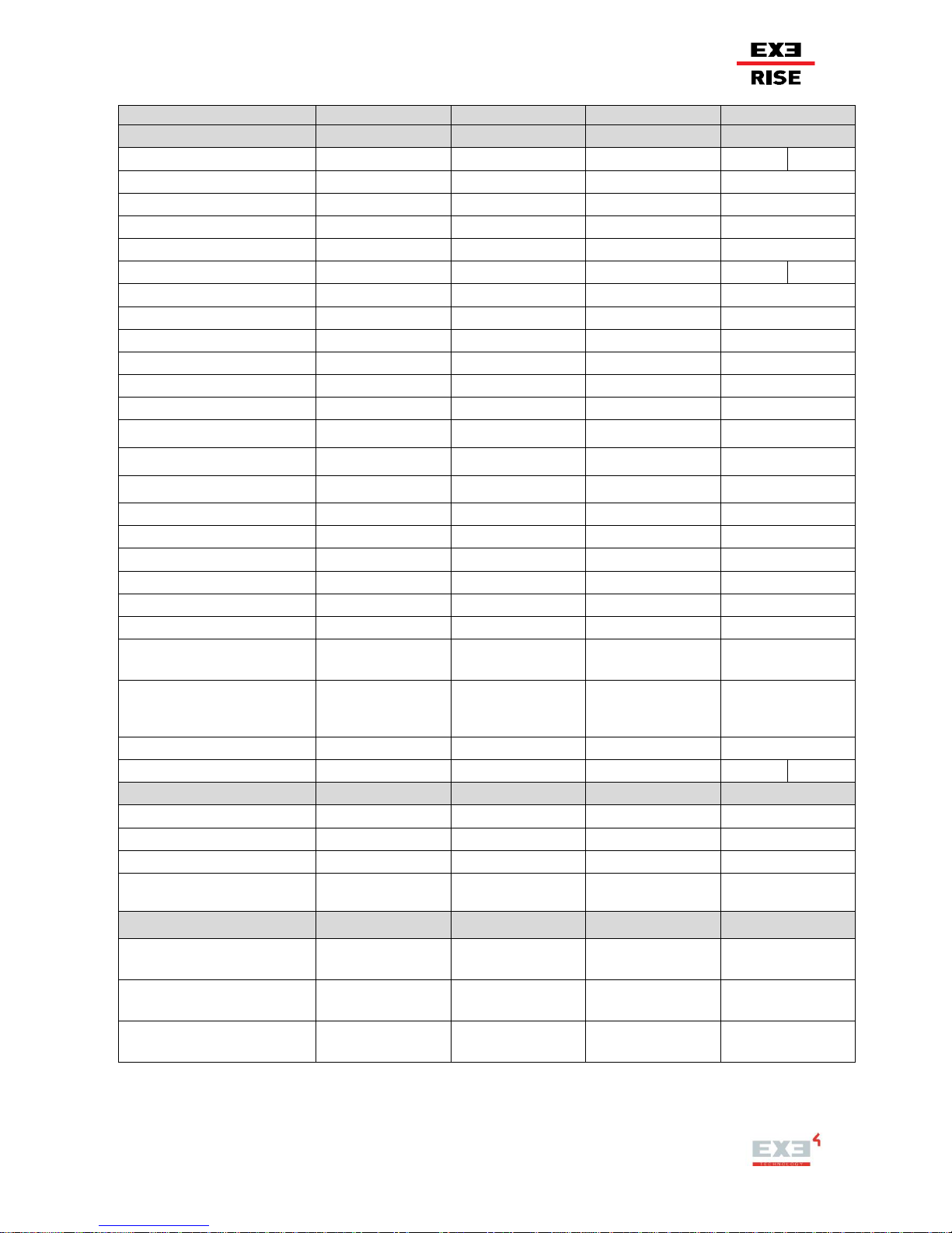
38 / 64
MODEL D8+ DC / LVC
D8+ 150kg
D8+ 300kg
D8+ 600kg
D8+ 800kg - 1200kg
Hoist Specifications
Hoist Specifications
Hoist Specifications
Hoist Specifications
Hoist Specifications
Working Load Limit (WLL)
150kg
300kg
600kg
800kg
1200kg
Lifting Speed @50Hz
4m/min
4m/min
4m/min
4m/min
Motor Power
0.5kW
0.8kW
1.0kW
1.6kW
Operating Voltage Δ / Y
230/400VAC - 3 - 50Hz
230/400VAC - 3 - 50Hz
230/400VAC - 3 - 50Hz
230/400VAC - 3 - 50Hz
3 ph Δ 230 VAC Y 400 VAC
Δ 2.70A – Y 1.56A
Δ 3.29 A – Y 1.90 A
Δ 3.59 A – Y 2.07 A
Δ 4.59 A – Y 2.65 A
Falls of Chain
1 1 1 1 2
Load Wheel
5 pockets
5 pockets
5 pockets
5 pockets
Protection Class
IP55 DIN 40050
IP55 DIN 40050
IP55 DIN 40050
IP55 DIN 40050
FEM Classification
2m
2m
2m
2m
Duty Factor of Motor
40%
40%
40%
40%
Starts Per Hour
240
240
240
240
Connection Cable Lenght
1m
1m
1m
1m
Δ Power Supply Connector (*)
CEE 16A 9h 230VAC –
3PH + G blue plug
CEE 16A 9h 230VAC –
3PH + G blue plug
CEE 16A 9h 230VAC –
3PH + G blue plug
CEE 16A 9h 230VAC –
3PH + G blue plug
Y Power Supply Connector
CEE 16A 6h 400VAC –
3PH + G red plug
CEE 16A 6h 400VAC –
3PH + G red plug
CEE 16A 6h 400VAC –
3PH + G red plug
CEE 16A 6h 400VAC –
3PH + G red plug
Control Supply Connector
(only LVC)
CEE 16A 4h 24VAC –
3PH + G yellow socket
CEE 16A 4h 24VAC –
3PH + G yellow socket
CEE 16A 4h 24VAC –
3PH + G yellow socket
CEE 16A 4h 24VAC –
3PH + G yellow socket
Noise Level
67.5 db @ full load
67.5 db @ full load
67.5 db @ full load
67.5 db @ full load
DC Brake System
2 2 2
2
DC Brake Size
06
06
08
10
DC Brake Power
20W
20W
25W
30W
DC Brake Operating Voltage
105VDC
105VDC
105VDC
105VDC
DC Brake Rated Torque
4Nm
4Nm
8Nm
16Nm
DC Brake Rated Torque
Reduction at the speed specified
x% (1500r/min)
87% (1500 r/min)
87% (1500 r/min)
85% (1500 r/min)
83% (1500 r/min)
Clutch Characteristics
Clutch is friction based
force-limiter.Clutch outside
the line of kinetic
movement.
Clutch is friction based
force-limiter.Clutch outside
the line of kinetic
movement.
Clutch is friction based
force-limiter.Clutch outside
the line of kinetic
movement.
Clutch is friction based
force-limiter.Clutch outside
the line of kinetic
movement.
Limit Switch (only LVC)
Not Provided
4 4 4
Selfweight
≈ 17.0kg
≈ 24.0kg
≈ 43.0kg
≈ 43.0kg
≈ 45.0kg
Chain Specifications
Chain Specifications
Chain Specifications
Chain Specifications
Chain Specifications
Size
4x12mm
6x18mm
8x24mm
8x24mm
Safety Factor
10:1
10:1
10:1
10:1
Selfweight
0.35kg/m
0.78kg/m
1.39kg/m
1.39kg/m
Material
Zinc Galvanized Steel
grade 80
Zinc Galvanized Steel
grade 80
Zinc Galvanized Steel
grade 80
Zinc Galvanized Steel
grade 80
Chain Bag Specifications
Chain Bag
Specifications
Chain Bag
Specifications
Chain Bag
Specifications
Chain Bag
Specifications
(Chain Length Up to 26m) Size Selfweight - External dimension Height
XS - 0,75kg 140x90mm - 400mm
S - 1,00kg 200x170mm - 340mm
M - 1,00kg 200x170mm - 420mm
M - 1,00kg 200x170mm - 420mm
(Chain Length 26/40m) Size Selfweight - External dimension Height
XS - 0,75kg 140x90mm - 400mm
M - 1,00kg 200x170mm - 420mm
L - 1,00kg 200x170mm - 580mm
L - 1,00kg 200x170mm - 580mm
(Chain Length From to 40m) Size
- Selfweight - External dimension
- Height
Not Provided
L - 1,00kg 200x170mm - 580mm
XL - 1,00kg 270x2100mm - 650mm
XL - 1,00kg 270x210mm - 650mm

39 / 64
3.6 EXE-Rise DRAWING
250kg D8 DC/LVC and 150kg D8+ DC/LVC
Figure 25: “EXE-Rise DRAWING: 250kg D8 DC/LVC and 150kg D8+ DC/LVC”
500kg D8 DC/LVC and 300kg D8+ DC/LVC
Figure 26: “EXE-Rise DRAWING: 500kg D8 DC/LVC and 300kg D8+ DC/LVC”

40 / 64
1000kg D8 DC/LVC and 600kg – 800kg D8+ DC/LVC
Figure 27: “EXE-Rise DRAWING: 1000kg D8 DC/LVC and 600kg – 800kg D8+ DC/LVC”
2000kg D8 DC/LVC and 1200kg D8+ DC/LVC
Figure 28: “EXE-Rise DRAWING: 2000kg D8 DC/LVC and 1200kg D8+ DC/LVC”

41 / 64
4. HANDLING AND INSTALLATION
When handling and unpacking the hoist you should use safe handling techniques.
Electric chain hoists must be assembled by qualified personnel. Always refer to your local areas manual
lifting directives, as well those mentioned in this manual.
Should the electric chain hoist be destined for operation outdoors then it is necessary to use a protection
cover to shield it from the effects of the weather. NB! This can also be protection against fine sand!
4.1 HANDING & TRANSPORTATION
The customer must carefully check if the goods are complete and undamaged upon delivery. Any damage in
transit is the responsibility of the carrier. The packaging should be disposed of in an environmentally friendly
manner. Ensure all routes and areas which are intended for handling are free from obstacles.
When working at height the user should employ relevant and suitable access and safety equipment.
Lifting, shifting and handling operations must be carried out by trained personnel. Do not halt, for any reason,
below suspended loads during lifting operations.
The package contains a label on the front and on the back side, reporting serial number, code, description
and number of pieces of EXE-Rise chain hoist. It means you have a chance of reading all labels when they
are stacked on a pallet as opposed to no chance if the labels are on top. The follow figure is an example of
packing label.
Figure 29: “EXE-Technology package label”

42 / 64
4.2 TRANSPORT AND STORAGE
- It is advised to transport the electric chain hoist in its original packaging or a dedicated flight case.
- Before putting your EXE Rise hoist in storage make sure all components are dry
- Use flight cases with ventilation openings for all compartments
- Keep the chain oiled to prevent corrosion
- Do not stack carton boxes in which the hoist comes from the factory higher than two
- Provide a clip on attachment point for the lift chain hook in the flight case. This minimises the risk of
chain becoming entangled during transport.
- When air freighted the pressure inside the hoist can increases and cause leakage of oil/grease.
This is temporary effect caused by difference in air pressure.
A Banksman should be present when moving goods with machinery such as lift trucks.
Packaging such as plastic bags, expanded polystyrene must not be released to the environment but must be
kept in order to pack again the hoist after using it.
4.2.1 Packaging storage
The goods are packaged in a way that offer protection from damage. This packaging should be stored in a
dry environment away from moisture, heat and temperatures from 10degrees Celsius up to 40degrees
Celsius
Should the hoist not be operated immediately, it is recommended to store it inside its packaging, in a
covered, dry and clean area, away from heat sources that might jeopardise its integrity.
4.2.2 Unpacking and ground handling of the hoist
Remove the hoist from its packaging. Lift the hoist by the handles.
- Check that the packaging label information are the same as those on the hoist plate.
- Check that the hoist has not suffered damage arising from an inadequate transport. Perform the
following checks;
- Make sure the plugs and cables are undamaged
- Check integrity of the hoist metal housing
- No cracks or dents must be present
- All casing screws should be present and tight
- Check for water ingress.
- Check that the sprung latches on the hooks are present and functioning correctly.
- Check chain bag for damage.
- Inspect the load chains for dents or notches
If a damage arising from shipment has been detected please refer to the accompanying document envelope
on the box for the claim procedure.
Possible claims related to hoist damages must be presented within 8 days from receipt of the goods; in any
case it must be pointed out that the hoist is subject to an accurate inspection in every part before being
packed and shipped to the customer.
Place the hoist on the ground and attach the chain bag; make sure that the screw closures of the bag
connecting links have been correctly closed.

43 / 64
4.3 SUSPENDING THE HOIST
It is the user’s responsibility to ensure all hanging points, lifting hardware and control systems are inspected
and tested prior before use.
Cables must be placed in such a way that they do not come into contact with sharp edges and do not run the
risk to be cut off or damaged. Cables must not be placed under tension.
4.3.1 Mounting the hoist “motor-down” (self-climbing mode)
1. Move the hoist in the required location whilst still in its packaging.
2. Connect the hoist to its control system.
3. For the first installation run the complete chain through the hoist and back. This way correct storage
of the chain in the bag or chain container is guaranteed
4. Connect the hook end of the chain to the fixing point at height. The hoist can then be operated and
run up to a working height position where the load to be connected.
4.3.2 Mounting the hoist in “motor-up“ position
5. Use an appropriate method of lifting the hoist body and attach the anchorage hook to the point of the
structure.
6. Connect the hook on the hoist body to the suspension point.
7. Connect the hoist to its control system.
8. For the first installation run the complete chain through the hoist and back. This ensures the chain
will be correctly stored in the chain bag.
9. Lower the lifting chain to its required height
Figure 30: “EXE-Rise motor up and down”

44 / 64
4.4 ELECTRICAL CONNECTIONS
Before connecting the hoist to the power supply, check that voltage and power of the electric supply
corresponds to those reported on the chain hoist plate. Check also that the earthing system is efficient.
Do not insert the plug of the hoist directly into a power socket. Only use a dedicated chain hoist controller.
Installers must equip the branch circuit with a grounding system, protection against current overloads and
short circuits that comply with the requirements of the laws on safety and health protection on work place of
the Country where the hoist is installed.
In order to avoid risk of electrocution and malfunction, check that all cables powering the hoist are protected
against possible external damages.
EXE Rise chain hoists are available in both direct and low voltage control. They must be connected to a
power and control system that is suitably designed to operate the chain hoists and handle the power
consumption of the motor.
EXE Rise hoists are factory set to be run with a voltage of 400 V AC. The DC hoist is fitted with a CEE 16A
6h 400VAC – 3PH +G black plug. plug as standard. The LVC hoist comes with a CEE 16A 4h 110VAC 3PH +G black socket.
Electrotechnical adjustments may only be performed by authorised specialists.
EXE Rise hoists are manufactured to be run with a voltage of 400 V AC. The DC hoist is fitted with a CEE
16A 6h 400VAC – 3PH +G black or red plug. plug as standard with IP RATE 67. The wiring must be done
according to the standard sequence following:
Low Voltage Control Direct Control
PIN
COLOR
L1
Brown
L2
Black
L3
Grey
PE
Yellow – Green
Table 18: “Plug wiring”
The LVC hoist comes with a CEE 16A 4h 110VAC - 3PH +G black or yellow socket, with IP RATE 67.
The wiring must be done according to the standard sequence following:
PIN
COLOR
FUNCTION
L1
Brown
Up
L2
Grey
Down
L3
Black
Common 24 VAC
PE
Yellow – Green
Earth
Table 19: “Socket wiring”
PIN
COLOR
L1
Grey
L2
Black
L3
Brown
PE
Yellow – Green

45 / 64
When power extension cords CEE 16A 6h 400VAC – 3PH +G and / or Control extensions CEE 16A 4h
110VAC - 3PH +G are used, you must make sure that the electrical connections have been made
according to the rules respecting the position of PIN to PIN for each pole plugs and sockets (L1-L1, L2-L2;
L3-L3, PE-PE). Incorrect wiring means that the hoist does not perform its function.
Do not insert the plug of the hoist directly into a power socket. Only use a dedicated chain hoist controller.
The chain hoist EXE-Rise LVC must only be connected electrically to a motor controller compatible to
command EXE- Rise LVC.
5. USE
STAY ALERT! Watch what you are doing and use common sense. Do not use the hoist when you are tired,
distracted or under the influence of drugs, alcohol or medication that can cause diminished control.
Improper operation of the hoist can create a potentially hazardous situation which, if not avoided, could result
in death or serious injuries. Permit only authorised and qualified personnel to operate the unit. Do not use
the hoist or any other overhead materials handling equipment for lifting persons.
Do not use the hoist unless it is perfectly efficient, even if the hoist still operates.
Do not use the emergency stop button to habitually stop hoist motion.
Do not carry out operations or manoeuvres on one’s own initiative that do not fall within one’s area of
expertise and can compromise the safety of everyone.
Do not wear loose fitting clothes as these can get entangled in moving parts.
Do pay attention at all times when operating the hoist.
Do ensure the chain container is not obstructed in any way.
Do stay clear of moving chains.
Do ensure chain is lubricated at all times.
Call your EXE Rise supplier if the hoist does not work properly.
If damaged or worn parts are detected do not use the hoist. Seek assistance for service of the unit.
During the movement of the load always appoint a responsible person to monitor and ensure the load is
safe. If the load encounters any obstruction stop movement immediately. If the load is being moved on
multiple hoists a safe operating procedure must be pre-defined.
Limit switch adjustment for LVC models: The device is calibrated in a standard way at the factory. Official
trained and competent operators can adjust it according to their specific needs.

46 / 64
5.1 ATTACHING AND MOVING THE LOAD
1. Insert the lifting hook into the load pick-up point.
2. Make sure chain travel is in the same direction as shown on the controls.
3. Check to be sure that the attachments to the load hook are firmly seated. Make sure the hook latches
are closed and not supporting any part of the load.
4. Check to ensure that the load point is in line with the hoist head. WHEN APPLYING A LOAD, IT
MUST BE DIRECTLY IN LINE WITH THE HOIST. AVOID OFF CENTRE LOADING OF ANY KIND.
5. Make sure the load has enough room to be free to move: no obstructions must be present along its
travel.
6. Make sure no other sound than the hoist can be heard
7. Have a clear view on the load. Other wise use spotters with appropriate means of communication.
They shall be in direct contact with the operator
8. Select each hoist one by one and move it just that far that it is under tension and pick up the load
9. Before moving the load check for twists in the load chain.
10. Level the load before lifting.
11. Select the travel direction of all hoist connected to the load
12. Move the load by operating the go button of the associated controller.
13. Raise the load only enough to check the attachments to the hook and load are firmly seated.
14. Move the load slowly to avoid shock and jerking of load chain. If there is any evidence of overloading,
immediately lower the load and remove the excess load.
15. Stop at intermediate heights to check if the structure is still in the required position
16. When the hoist is are at trim height apply a secondary safety if required. Follow the instructions as
given in the chapter “safety instructions”
17. Switch of the hoist main circuit breaker to avoid un intended operation
5.2 LOWERING AND DISCONNECTING THE LOAD
It shall be noted that lowering a load suspended on multiple hoist incorporates many more risk of overload as
lifting.
If one hoist is not following the lift sequence it is very likely it immediate is overloading itself, its suspension
point and the pickup point at the load:
1. Switch on the main circuit breaker of the hoist controller
2. Check if the travel path of the load is free of obstructions
3. Clear the area from people
4. Make sure no other sound than the hoist can be heard
5. Select the operation direction to “down” for each hoist connected to the load
6. Have a clear view on the load. Other wise use spotters with appropriate means of communication.
They shall be in direct contact with the operator
7. Activate all hoist by pressing the “Go” button
8. Check if all hoist are running. If not lift the load to its original position and solve the problem
9. Lower the load till the hoist are un loaded
10. Remove the hoist from their load. Use if possible its own lifting chain to place it back in its flight case.
11. Disconnect the power supply from the hoist
12. Disconnect the lifting chain
13. Make sure the chain is fed back in the chain bag in an appropriate way without getting entangled.

47 / 64
5.3 LIMIT SWITCH SETTING AND RE-SETTING
Manufacturer set limit switch as follow.
ULTIMATE UP between 3th and 4
th
links
STANDARD UP between 9
th
and 10
th
links
STANDARD DOWN at the 21th link
ULTIMATE DOWN at the 16
th
link
CHAIN STOP at the 11th link
Any Limit Switch re-setting is prohibited. Only RWM authorised service engineers are allowed to carry out resetting of limit switch.
320kg LVC model and 160kg D8+ hoist come without limit switch.
For a double reeved hoist like the 2000kg version, the length of chain travel is double. This reduces the lifting
height to 24.5 metres.
5.4 TURN 1000kg SINGLE REEVE IN 2000kg DOUBLE REEVE
EXE-Rise chain hoist D8 1000kg single reeve (DC and LVC) can be turned in D8 2000kg double reeve (DC
and LVC). The procedure to be performed is reported below:
1) Make sure the lifting chain is just 100cm long before modifying the hoist.
2) Reverse barycenter, rotating hoist body hook of 180° as in figure below. Unscrew the screws of the
plate, rotate 180° and tighten the screws, that they are M16 (8,8 steel) and the correct torque for
tightening these screws is 198 Nm (see figure 32).
Figure 31: “Reversing of barycenter”
3) Procure lift “chain hook” with load well for 8x24mm chain and “dead end block 8x24mm chain” (see
figure 33).
Figure 32: “Required Components”

48 / 64
4) Remove the lifting hook.
5) Remove Aluminum Frame Block (see figure 34).
Figure 33: “Removing the Frame Block”
6) Feed the lifting chain through the new lift hooks pulley. Make sure the chain is not twisted (see
figure 35).
Figure 34: “Replacement of the Chain hook”
7) Re-connect the chain to the aluminum frame block (see figure 36).
Figure 35: “Re-applying of the frame block”
8) Run the chain minimum 2 meter through the lift hook to ensure good operation.
49 / 64
6. INSPECTIONS
For a correct and safe use of EXE-Rise chain hoist it’s important to carry out appropriate inspections and
control. RWM recommended to comply with the frequency of inspections and follow the check reported in
this chapter.
6.1 INITIAL AND EACH ASSEMBLY INSPECTION AND CONTROLS
The purpose of the following test and inspection is to ensure the hoist has been correctly assembled,
installed, is not damaged and is safe to use. RWM recommended to perform the following checklist
When handling and unpacking the hoist you should use safe handling techniques.
The following test should be carried out prior to each new use of the hoist.
Visual inspections and controls
Visual inspections and controls should be carried out on the following elements to check for any damage or
faulty parts:
Presence and congruence of use and
maintenance manual, wiring diagram and
declaration of conformity of EXE-Rise chain
hoist
Identification and congruence of CE
marking and the data plate on the EXERise body
Correspondence between the power supply
and that provided for the hoists
Any visible damage to the hoist body, hook,
chain, bag, Quick Link and controller.
The value of the power supply is within the
+/-10% limits of the nominal value
Body work and Chain hook
Connections to the hoist controller
Chain bag connection
Power and control cables from the hoist to
the hoist controller
Load chain
Functional inspections and controls
Functional inspections and controls should be carried out on the following elements to check for any damage
or faulty parts:
Connect the hoist to a suitable controller
Listen for any strange noises from the hoist
while chain is running
Operate the hoist in both directions to
check phasing is correct. If not correct the
sequence
Chain should run smoothly into the chain
bag
Check E-stop of the controller is working
correctly
Ensure chain is not allowed to bunch up
while entering or exiting the hoist. Chain
should be allowed to run clear of the hoist.
Check the chain runs smoothly through the
hoist
Check all functions of the controller

50 / 64
6.2 FREQUENT AND PERIODICAL INSPECTION
Here the term inspection refers to the visual examination of the hoist and its accessories.
In order to keep a continuous and satisfactory operation inspection intervals must be determined by the
individual application and are based on the type of service to which the hoist will be subjected and the
degree of exposure to wear, deterioration or malfunction of the critical components. Check periodically that
all the labels are present and legible on the hoist.
In addition to the suggested inspection program below, please also refer to the local regulations relating to
lifting machinery. Appropriate actions as an outcome of the inspection and testing regime can be found in the
chapter “maintenance “
The type of service to which the hoist is subjected can be classified as "Normal", "Heavy", or "Severe".
Normal Service: Involves operation with randomly distributed loads within the rated load limit, or
uniform loads less than 65% of rated load for not more than 25% of the time.
Heavy Service: Involves operating the hoist within the rated load limit which exceeds normal service.
Severe Service: Normal or heavy service with abnormal operating conditions.
Two classes of inspections – frequent and periodic – can be performed
Frequent Inspections: These inspections are visual examinations by the operator or other designated
personnel. Records of such inspections are not required. The frequent inspections
are to be performed monthly for normal service, weekly to monthly for heavy service,
and daily to weekly for severe service, and they should include those items listed in
Table 14.
Periodic Inspections: These inspections are visual inspections of external conditions by an appointed
person. Records of periodic inspections are to be kept for continuing evaluation of
the condition of the hoist. Periodic inspections are to be performed yearly for normal
service, every six months for heavy service and quarterly for severe service, and
they are to include those items listed in Table 15.
Any deficiencies are to be corrected before the hoist is returned to service. Be aware that the external
conditions may show the need for more detailed inspections, which, in turn, may require the use of nondestructive type testing.
TYPE OF SERVICE
ITEM
Normal
Heavy
Severe
a) Brake for evidence of slippage.
b) Control functions for proper operation.
c) Hooks for damage, cracks, twists, excessive opening, latch engagement and
latch operation
d) Load chain for adequate lubrication, as well as for signs of wear, damaged links
or foreign bodies
e) Load chain for proper reeving and twists.
Monthly
Weekly to
monthly
Daily to weekly
Table 20: “Minimum frequent inspections”
51 / 64
TYPE OF SERVICE
ITEM
Normal
Heavy
Severe
a) All items listed in Table 8 for frequent inspections.
b) External evidence of loose screws, bolts, nuts.
c) External evidence of worn, corroded, cracked or distorted hook block,
suspension screw, bearings and dead end block and chain pin.
d) External evidence of damage to hook retaining nut and pin.
e) Check the integrity of the power plug of the chain hoist and control socket for
LVC models.
f) Check the electrical cords and cables and controller for damaged insulation.
g) Inspect for signs of lubricant leaks.
h) Setting and functioning of the slip clutch
Yearly
Every six months
Every three
months
Table 21: “Minimum periodic inspections”
6.2.1 Chain Inspection
Chain should feed smoothly into and away from the hoist or hook block. If chain binds, jumps or is noisy,
first clean and lubricate it. If trouble persists, inspect chain and mating parts for wear, distortion or other
damage.
The chain stop at the end of each lifting chain shall be placed at 11 links from the “dead end”. This dead end
is your reference for chain defaults as it never will be subject to load or wear and tear.
Lubrication:
Chain should always be kept well lubricated. No chain link may be overlooked as this can lead to premature
wear. Change-over links especially should be lubricated. Change-over links are those links which stop on,
resp. immediately at the inlet of the drive and reversing wheels at constant stroke when switching from lifting
to lowering. Beside the contact point of 2 links need sufficient lubrication.
Inspecting the chain and chain wheel:
The chain must be inspected at regular intervals, but at least once annually, in accordance with the
stipulations of ISO 7592 and the valid accident prevention regulations in the country of use. As the frequency
of use increases, the chain inspection program should be reviewed and carried out at more regular intervals.
Increased use will mean wear, corrosion, the effects of the heat and greater susceptibility to faults occur.
The inspection includes detecting surface damage of the links such as deformation, cracks, wear and
corrosion. The choice of a suitable lubricant is dependent on the operating environment. Please contact
RWM for recommendations of appropriate lubricants.
For usage a high pressure resistant lubricant will suffice.
During inspection, the chains must be examined along their entire length, including the hidden parts. If the
lifting equipment is frequently used with a constant lifting distance or if switchover from upward to downward
often takes place in the same area, a particularly thorough inspection and lubrication is required in this
switch-over area. Together with the chain the wheels, chain guide and fixing parts should be inspected for
damage, corrosion, abnormal area of wear or other defects.

52 / 64
Particular attention should be paid to the condition of all bolts and safety components. If defects are
discovered the hoist must be taken out of service and repaired immediately.
TIP! To detect surface damage and deformations on the external surfaces of the links, use a piece of cotton
fabric and pull the chain through. Any surface damage such as nicks or cracks will hook catch on the fibres
of the fabric and thus can be easily detected.
Discard criteria of chain:
The chain must be replaced if the average wire diameter (dm) has been reduced due to wear by more than
10% of the nominal thickness at any point on the chain link.
The average wire diameter dm=(d1+d2):2 ≤ 0.9d, whereby the average wire diameter (dm) is calculated from
two individual values d1 and d2 measured rotated through 90° with respect to each other. The chain must be
replaced if a single chain link is permanently lengthened or if the inner pitch t of the individual link has
increased in size by more than 5% as a result of wear.
The chain must also be replaced if the inner pitch 11t has increased in size by more than 2% along a
measuring section of 11 chain links.
The lubricant shall sit at the contact points between to chain links as this part is subject to the utmost wear
and tear
Chain wheel inspection:
If the chain is found to have reached the point of wear of 2% pitch enlargement (over 11t), the lift wheels
must be inspected carefully. Damaged wheels have to be replaced together with the chain. If no severe wear
has occurred to the lift wheel pockets the lift wheels do not have to be replaced.
External chain guide inspection:
The external chain guide helps feed the chain properly into the lift wheel. Its shape is specially designed in
order to disentangle chain before entering the hoist.
Excessive wear makes to the guide reduces its functionality. Wear that is apparent on one side of the chain
guide clearly indicates side pull on a loaded hoist. In both cases the chain guide shall be replaced.
Figure 36: “External chain guide plate”

53 / 64
6.2.2 Hook Inspection
Hooks damaged from chemicals, deformations, cracks or which have a 10° twist from the hook’s unbent
plane must be replaced.
If the throat of the hook is deformed or has excessively opened enough to allow the latch to not engage with
the tip of the hook correctly, it must be replaced. Any hook that is twisted or has excessive opening indicates
abuse or overloading of the unit. Inspect other load sustaining parts, hook block screws, load pins and chain
block body for damage.
Check and inspect that the spring latch is not damaged or bent and that it operates properly with sufficient
spring pressure to keep the latch tightly closed against the tip of the hook and allow the latch to spring back
to the tip when released.
If the latch does not operate properly, it should be replaced. The check on the max hook opening allowed
see drawings and dimensions below.
6.2.3 Chain Bag Inspection
Chain bags should be inspected for signs of excessive wear and tear to the fabric of the bag and the
attachment loops. Damaged bags shall be replaced at all times.
Chain bags shall be filled to a maximum of 75% .
Chain bags shall be suspended by Quicklinks or Carabiners made according to DIN 56927 or equivalent
standard. They shall have a 5:1 safety factor as suitable for overhead suspension. Some bags are supplied
with a suitable rated captive spring hook. Only rated hooks supplied by RWM should be used.
Any attaching devices should also be inspected. Danged or worn devices should be discarded immediately
and replace.
6.3 PERIODICAL CONTROLS
The hoist must be tested as often as deemed necessary, based on usage logs, or at least once a year.
Testing should be carried out by an authorised expert. In case of heavy services or intensive use, the user
must carry out additional extraordinary testing based on his own risk evaluation. Periodic testing must be
carried out by the authorised RWM maintenance service engineer.
Testing shall consist of lifting a dynamic load in order to test the functioning and setting of the slip clutch and
the brake.
In addition, the slipping properties of the clutch and brake can be affected by, but not limited to, the position
of the pocket wheel, operation in extreme temperatures (above 65dgr. Celsius or below -10dgr. Celsius),
humidity or fluctuations in the friction material. This could lead different values of the clutch setting as seen
on the initial test report.
The clutch settings of the EXE RISE hoist are set at 120% of the nominal load to meet the German
standards for the use of hoists above people. Due to the nature of the clutches and the above conditions,
these settings can vary easily by +/- 10%... The testing shall be performed with a suspended load of 120% of
the maximum WLL. Other countries may have different regulations. However, clutch settings shall remain in
between 110% and 160% at all times (EN14992-2).

54 / 64
6.4 EXTRAORDINARY INSPECTION
In case of extraordinary events which can jeopardise the safety of the working equipment, extraordinary
testing must be carried out. In particular, extraordinary events include accidents, modifications to the hoist,
prolonged downtime periods and natural phenomena.
Testing must be carried out only by authorised personnel, duly authorised for the purpose.
In addition to the above inspection and testing procedure, a preventive maintenance program should be
established to prolong the useful life of the hoist and maintain its reliability and continued safe use. The
program should include the periodic and frequent inspections with particular attention being paid to the
lubrication of the various components using the recommended lubricants.

55 / 64
7. MAINTENANCE AND REPAIR
Visual inspection and testing of the hoist and lubricating the chain are the only interventions that should be
undertaken by the user of the hoist.
All other maintenance, replacement, adjustment interventions that involve the opening of the hoist housing
should only be carried out by RWM authorised service engineers.
The hoist must therefore be delivered to RWM authorised centre that will issue special control and
maintenance reports.
Maintenance and service are preventive measures designed to preserve the full functionality of electric chain
hoists. Non-compliance with maintenance and service routines can result in reduction in the useful function
of and/or damage to chain hoists.
Maintenance work encompasses visual checks and cleaning routines. Service work includes additional
functional checks. During the functional checks, all securing elements and cable clamps must be checked for
secure seating.
During maintenance and service work, general accident prevention directions, special safety directions as
well as hazard protection instructions should be followed.
Before carrying out any kind of maintenance, repair, cleaning or any activity that requires a manual
intervention on the machine, disconnect the power supply to the hoist.
Ensure the power cannot be re-connected to the hoist be securing or clearly marking the plug “do not
connect”.
7.1 CHAIN MAINTENANCE
Use of commercial or other manufacturers’ chain and spare parts to repair the hoist may cause load loss.
Use only chains supplied by the manufacturer.
The valid accident prevention regulations and the stipulations of ISO 7592 must be observed during all
maintenance work.
7.1.1 Cleaning Chain
Clean the load chain with acid-free solvent and coat with new high pressure oil. Wipe excess oil to prevent
dripping. Never apply grease to the chain.
7.1.2 Lubrication of Chain
Lubricated chain has a much higher (15-20 times) lifecycle than a dry chain. We recommend to lubricate the
chain along its entire length before putting into operation. It must be ensured that all chain links are
lubricated. During lubrication, ensure that the lubricant penetrates into connection point between chain links.
This spot is most susceptible to wear. Change-over link should be lubricated especially careful. Change-over

56 / 64
links are those links which stop on, resp. immediately at the inlet of the drive and reversing wheels at
constant stroke when switching from lifting to lowering. These chain links are charged especially heavy by
dynamic vibrations and have therefore to be lubricated carefully in shorter intervals. The choice of a suitable
lubricant is dependent from the operating place and the existent environment conditions. An appropriate
lubricant recommendation can be inquired by RWM. For average applications a high pressure resistant
lubricant will do.
7.2 BRAKE AND LIMIT SWITCH MAINTENANCE / ADJUSTMENT
EXE-Rise chain hoist are equipped with an INTORQ brake.
1. Measure the rotor thickness of the brake by means of a Vernier Caliper gauge. (See table below for
allowable Values)
2. If required, exchange the entire rotor. See chapter “SPARE PART “ for further instruction.
3. Check the air gap ”sL” near the fixing screws between the armature plate and stator using afeeler
gauge.
4. Compare air gap measured to maximally permissible air gap ”sL max.”, (see table below)
5. If required, set air gap to ”sLN”
Figure 37: “Brake components”
Any intervention on the brake is prohibited. Only RWM authorised service engineers are allowed to carry out
maintenance work on brakes.
57 / 64
7.3 CLUTCH AND GREAR BOX MAINTENANCE / ADJUSTMENT
Any intervention on the clutch is prohibited. Only RWM authorised service engineers are allowed to carry out
maintenance work on clutches.
Do not use any kind of fluid or spray which causes a lubrication effect on the clutch friction disk. For cleaning
use a resolving agent suitable for the application.
7.4 TROUBLESHOOTING
TROUBLE
PROBABLE CAUSE
CHECK AND REMEDY
1) Hoist does
not respond to
the controller
or control
device
a) No voltage at hoist main line or control circuit
switch open; control line fuse blown or circuit
breaker tripped.
a) Close switch, replace fuse blown.
b) Phase failure – power cable damaged; power
supply cable damaged; broken stator winding.
b) Check for electrical continuity and
repair or replace defective part.
c) Open control circuit – primary transformer fuse
blown; broken transformer winding; broken
up/down limit switch; up/down contactor coil
broken; loose connection or broken wire inside the
circuit; contactor jammed.
c) Check electrical continuity and
repair or replace defective part.
d) Wrong voltage or frequency.
d) Use the voltage and frequency
indicated on hoist identification plate.
e) Low voltage.
e) Check the power supply voltage.
f) The brake does not open – the brake power
supply coil is open, short-circuited or broken;
circuit breaker blown.
f) See item c).
g) Excessive load.
g) Reduce loading to the capacity limit
of hoist as indicated on the
identification plate.
2) Chain
moves in the
opposite
direction
a) Three-phase power inverted.
a) Refer to installation instruction in
chapter 4.
3) Hook lowers
but will not
raise.
a) Excessive load mechanical load clutch slipping.
a) Refer to installation instruction in
chapter 4.
b) Open hoisting circuit-open or shorted winding in
reversing contactor coil loose connection or
broken wire in circuit; control station contacts not
making; upper limit switch contacts open.
b) Check electrical continuity and
repair or replace defective part.
c) Phase failure.
c) See item 1b
4) Hook raises
but will not
lower.
a) Open control circuit – "down" contactor coil
broken or short-circuited; "down" limit switch
broken.
a) Check electrical continuity and
repair or replace defective part.
5) Hook lowers
when hoisting
control is
operated.
a) Phase failure
a) See item 1B
b) Phase reversal.
b) Refer to installation instruction in
chapter 3.

58 / 64
6) Hook does
not stop
promptly
a) Brake slipping.
a) Check brake.
b) Excessive load.
b) See item 1H
7) Hoist
operates
sluggishly
a) Excessive load
a) See item 1H
b) Low voltage
b) Correct low voltage condition.
c) Phase failure or unbalanced current in the
phases.
c) See item 1b.
d) Brake dragging.
e) Check brake.
8) Motor
overheats.
a) Low voltage.
a) Correct low voltage conditions.
b) Excessive load.
b) See item 1H.
c) Extreme external heating.
c) Above an ambient temperature of
40°C (104°F) the frequency of hoist
operation must be limited to avoid
overheating of motor. Special
provisions should be made to
ventilate the space or shield the hoist
from radiation.
d) Frequent starting or reversing.
d) Avoid excessive inching, jogging or
plugging. This type of operation
drastically shortens the motor and
contactor life and causes excessive
brake wear.
e) Phase failure or unbalanced current in the
phase.
e) See item 1B.
f) Brake dragging.
f) Check brake.
9) Hook fails to
stop at either or
both ends of
travel.
a) The limit switches do not open the circuits
because they are stuck. Limit switches not
adjusted correctly.
a) Check switch connections,
electrical continuity and mechanical
operation. Check the switch
adjustment of Limit Switches.
b) Limit switch shaft not rotating.
b) Check for damaged Limit Switch
gears and their fixing.
c) Travelling nuts not moving along shaft-guide
plate loose; shaft or nut threads damaged.
d) Tighten guide plate screws.
Replace damaged part.
10) Hook
stopping point
varies.
a) Limit switch not holding adjustment.
a) see item 9.
b) Brake not holding.
b) check the brake.
Table 22: “Troubleshooting based on hoist behaviour”

59 / 64
8. SPARE PART
250kg D8 DC/LVC and 150kg D8+ DC/LVC
Figure 39: “Spare Part of D8 250kg DC/LVC and D8+ 150kg DC/LVC”
Table 23: “Spare Part of D8 250kg DC/LVC and D8+ 150kg DC/LVC”
CODE
DESCRIPTION
CODE
DESCRIPTION
COVER
GEAR BOX
COVER
ROTOR
BRAKE FLANGE
STATOR
GEAR BOX HOUSING
BRACKET
GEAR BOX FLANGE
FRAME BLOCK
LOAD WHEEL HOUSING
LIMIT SWITCH
LOAD WHEEL FLANGE
REVERSING CONTACTOR
MOTOR HOUSE
FUSES
BODY SWIVEL HOOK
RECTIFIER
CHAIN SWIVEL HOOK
TRASFORMER
CHAIN STOP
SCREW
EXTERNAL CHAIN GUIDE
LOAD WHEEL
DOUBLE BRAKE

60 / 64
500kg D8 DC/LVC and 300kg D8+ DC/LVC
Figure 40: “Spare Part of D8 500kg DC/LVC and D8+ 300kg DC/LVC”
Table 24: “Spare Part of D8 500kg DC/LVC and D8+ 300kg DC/LVC”
CODE
DESCRIPTION
CODE
DESCRIPTION
COVER
GEAR BOX
COVER
ROTOR
BRAKE FLANGE
STATOR
GEAR BOX HOUSING
BRACKET
GEAR BOX FLANGE
FRAME BLOCK
LOAD WHEEL HOUSING
LIMIT SWITCH
LOAD WHEEL FLANGE
REVERSING CONTACTOR
MOTOR HOUSE
FUSES
BODY SWIVEL HOOK
RECTIFIER
CHAIN SWIVEL HOOK
TRASFORMER
CHAIN STOP
SCREW
EXTERNAL CHAIN GUIDE
LOAD WHEEL
DOUBLE BRAKE

61 / 64
1000kg D8 DC/LVC and 600kg D8+ DC/LVC
2000kg D8 DC/LVC and 1200kg D8+ DC/LVC
Figure 22: “Spare Part of D8 1000kg DC/LVC, D8 2000kg DC/LVC and D8+ 600kg DC/LVC, D8+ 1200kg
DC/LVC”
Table 25: ““Spare Part of D8 1000kg DC/LVC, D8 2000kg DC/LVC and D8+ 600kg DC/LVC, D8+ 1200kg
DC/LVC”
CODE
DESCRIPTION
CODE
DESCRIPTION
COVER
GEAR BOX
COVER
ROTOR
BRAKE FLANGE
STATOR
GEAR BOX HOUSING
BRACKET
GEAR BOX FLANGE
FRAME BLOCK
LOAD WHEEL HOUSING
LIMIT SWITCH
LOAD WHEEL FLANGE
REVERSING CONTACTOR
MOTOR HOUSE
FUSES
BODY SWIVEL HOOK
RECTIFIER
CHAIN SWIVEL HOOK
TRASFORMER
CHAIN STOP
SCREW
EXTERNAL CHAIN GUIDE
LOAD WHEEL
DOUBLE BRAKE

62 / 64
9. DEMOLITION AND DISPOSAL
Before carrying out demolition and disposal of the hoist, complete the working cycle and disconnect power.
Upon demolition, plastic parts must be separated from electric components and must be sent to selective
collections according to regulations in force.
With regard to metal housing, aluminium parts should be separated from all other metals before sending for
recycling.
To dispose of hydraulic oil, please refer to the product safety report or data sheet.
It is prohibited to pour rejected liquids such as oils, circuit liquids, etc. on the ground or into drainage
systems. Please dispose of components or fluids that may be hazardous to health or the environment in a
manner compliant with local regulations.
During operations of hydraulic oil replacement and disposal, the operator must wear gloves and protective
overalls indicated in the product safety report.

63 / 64
10. DECLARATION MODELS
The declaration of conformity completed, dated and signed is attached to this
manual. This document is integral part of the manual.

64 / 64
EXE-RISE CHAIN HOIST
IS EXCLUSIVELY DISTRIBUTED BY
LITEC ITALIA S.R.L.
Via Martin Luther King 70, I-31032 Casale sul Sile (TV), Italy
Tel: +390422997300 Fax: +390422997399
www.exetechnology.com
www.litectruss.com
 Loading...