

exemys SGW1-IA3-MMP User Manual

SGW1-IA3-MMP – Modbus Multiplexer Exemys
www.exemys.com SGW1-IA3-MMP User’s Manual Rev. 1 1

SGW1-IA3-MMP – Modbus Multiplexer Exemys
www.exemys.com SGW1-IA3-MMP User’s Manual Rev. 1 2
Exemys products are constantly evolving to meet the needs of our customers. For this reason,
the specifications and capabilities are subject to change without notice.
Find updates at www.exemys.com
Copyright © Exemys, 2007. All rights reserved.

SGW1-IA3-MMP – Modbus Multiplexer Exemys
www.exemys.com SGW1-IA3-MMP User’s Manual Rev. 1 3
Page Index
1111 Introduction
IntroductionIntroduction
Introduction ________________________________
________________________________________________________________
________________________________________________________
________________________________________________
________________________ 4444
1.1
1.11.1
1.1 User’s Manual Purpose
User’s Manual PurposeUser’s Manual Purpose
User’s Manual Purpose ________________________________
________________________________________________________________
________________________________________________
________________________________
________________ 4444
1.2
1.21.2
1.2 Product Overview
Product OverviewProduct Overview
Product Overview ________________________________
________________________________________________________________
____________________________________________________
________________________________________
____________________ 4444
1.3
1.31.3
1.3 Ordering Codes
Ordering CodesOrdering Codes
Ordering Codes ________________________________
________________________________________________________________
_____________________________________________________
__________________________________________
_____________________ 5555
1.4
1.41.4
1.4 Technical Specifications
Technical SpecificationsTechnical Specifications
Technical Specifications ________________________________
________________________________________________________________
_______________________________________________
______________________________
_______________ 5555
2222 Installation
InstallationInstallation
Installation ________________________________
________________________________________________________________
________________________________________________________
________________________________________________
________________________ 6666
2.1
2.12.1
2.1 Power
PowerPower
Power ________________________________
________________________________________________________________
____________________________________________________________
________________________________________________________
____________________________ 6666
2.2
2.22.2
2.2 Connections
ConnectionsConnections
Connections ________________________________
________________________________________________________________
________________________________________________________
________________________________________________
________________________ 6666
2.3
2.32.3
2.3 LED indicators
LED indicatorsLED indicators
LED indicators ________________________________
________________________________________________________________
______________________________________________________
____________________________________________
______________________ 7777
3333 Configuration
ConfigurationConfiguration
Configuration ________________________________
________________________________________________________________
______________________________________________________
____________________________________________
______________________ 8888
3.1
3.13.1
3.1 Master / Slave configuration parameters
Master / Slave configuration parametersMaster / Slave configuration parameters
Master / Slave configuration parameters ________________________________
________________________________________________________________
___________________________________
______
___ 9999
3.2
3.23.2
3.2 Serial Port Configuration
Serial Port ConfigurationSerial Port Configuration
Serial Port Configuration ________________________________
________________________________________________________________
_____________________________________________
__________________________
_____________ 10
1010
10
3.3
3.33.3
3.3 RTS Control Configuration
RTS Control ConfigurationRTS Control Configuration
RTS Control Configuration ________________________________
________________________________________________________________
____________________________________________
________________________
____________ 11
1111
11
3.4
3.43.4
3.4 Slave ranges, Configuration
Slave ranges, ConfigurationSlave ranges, Configuration
Slave ranges, Configuration ________________________________
________________________________________________________________
___________________________________________
______________________
___________ 11
1111
11
3.5
3.53.5
3.5 Other configuration settings.
Other configuration settings.Other configuration settings.
Other configuration settings. ________________________________
________________________________________________________________
__________________________________________
____________________
__________ 14
1414
14
4444 TTTTypical Usage Modes
ypical Usage Modesypical Usage Modes
ypical Usage Modes ________________________________
________________________________________________________________
________________________________________________
________________________________
________________ 15
1515
15
4.1
4.14.1
4.1 Multiplexer Mode
Multiplexer ModeMultiplexer Mode
Multiplexer Mode ________________________________
________________________________________________________________
__________________________________________________
____________________________________
__________________ 15
1515
15
4.2
4.24.2
4.2 De
DeDe
De----Multiplexer Mode
Multiplexer ModeMultiplexer Mode
Multiplexer Mode ________________________________
________________________________________________________________
________________________________________________
________________________________
________________ 16
1616
16
4.3
4.34.3
4.3 Converter Mode
Converter ModeConverter Mode
Converter Mode ________________________________
________________________________________________________________
____________________________________________________
________________________________________
____________________ 17
1717
17
4.4
4.44.4
4.4 Interchange memory Mode
Interchange memory ModeInterchange memory Mode
Interchange memory Mode ________________________________
________________________________________________________________
____________________________________________
________________________
____________ 17
1717
17
5555 Monitoring
MonitoringMonitoring
Monitoring ________________________________
________________________________________________________________
_______________________________________________________
______________________________________________
_______________________ 18
1818
18
A. FIRMWARE UPGRADE
A. FIRMWARE UPGRADEA. FIRMWARE UPGRADE
A. FIRMWARE UPGRADE 19
1919
19
B. FACTORY SETTINGS
B. FACTORY SETTINGSB. FACTORY SETTINGS
B. FACTORY SETTINGS 22
2222
22
C. DIN RAIL MOUNT
C. DIN RAIL MOUNTC. DIN RAIL MOUNT
C. DIN RAIL MOUNT 23
2323
23

SGW1-IA3-MMP – Modbus Multiplexer Exemys
www.exemys.com SGW1-IA3-MMP User’s Manual Rev. 1 4
1 Introduction
1.1 User’s Manual Purpose
The purpose of this manual is to provide the instructions for installing and operating the
SGW1-IA3-MMP quickly and simply. The manual begins with a general description of the
product, following the instructions for the correct installation of the hardware. The
configuration and operation of the device is detailed later.
Acr
onym
Descrip
tion
PC Personal Computer
USB Universal Serial Bus
LED Led Indicator
GND Ground (Reference)
1.2 Product Overview
The SGW1-IA3-MMP is a Modbus communications multiplexer / converter over serial ports. It
allows you to connect Modbus RTU / ASCII masters to Modbus RTU / ASCII slaves. Each of
the serial devices can operate with Baud Rate, Data Bits, Parity, Bits Stop and different
Modbus protocol type (RTU or ASCII).
The SGW1-IA3-MMP orders the interrogations coming from the different masters assigning a
priority according to the order of arrival of the different masters, and then sends them to the
slaves.
As an additional function, the device allows the exchange of information between Modbus
masters through the 1000-byte exchange memory that can be read and written by any of the
connected masters.

SGW1-IA3-MMP – Modbus Multiplexer Exemys
www.exemys.com SGW1-IA3-MMP User’s Manual Rev. 1 5
1.3 Ordering Codes
Part Number Description
SGW1-4B0
4B04B0
4B0-00
0000
00-IA3-MMP
4 RS-232 / RS-485 ports
SGW1-13B0
13B013B0
13B0-00
0000
00-IA3-MMP-CF
CFCF
CF
1 RS232with flow control + 3 RS-232 / RS-485 ports
1.4 Technical Specifications
Communication
CommunicationCommunication
Communication Protocol
ProtocolProtocol
Protocol
Modbus RTU, Modbus ASCII.
Communication Ports
Communication PortsCommunication Ports
Communication Ports
4 RS232/RS485 + 1 USB type B.
Configura
ConfiguraConfigura
Configuration
tiontion
tion
Serial USB console.
Firmwa
FirmwaFirmwa
Firmware upgrade
re upgradere upgrade
re upgrade
Via serial RS232 console
LED’s
LED’sLED’s
LED’s Indica
IndicaIndica
Indicators
torstors
tors
Power, Modbus data
Dimensions
DimensionsDimensions
Dimensions
100 mm x 22,5 mm x 112 mm (Height x Width x Length).
Power
PowerPower
Power
10 a 30 [Vdc].
12 Vdc – 70 [mA]
24 Vdc – 40 [mA].
Temperatur
TemperaturTemperatur
Temperatures
eses
es
Operation: -15 to 65 ºC.
Storage: -40 to 75 ºC.
Warranty
WarrantyWarranty
Warranty
1 year
Technical support included.
SGW1-IA3-MMP – Modbus Multiplexer Exemys
www.exemys.com SGW1-IA3-MMP User’s Manual Rev. 1 6
2 Installation
2.1 Power
The SGW1-IA3-MMP accepts a power supply in the range of +10 to 30 Vdc and must connect
the positive of the power supply to terminal No. 17 and the negative of the power supply to
terminal No. 18, as shown in the following figure:
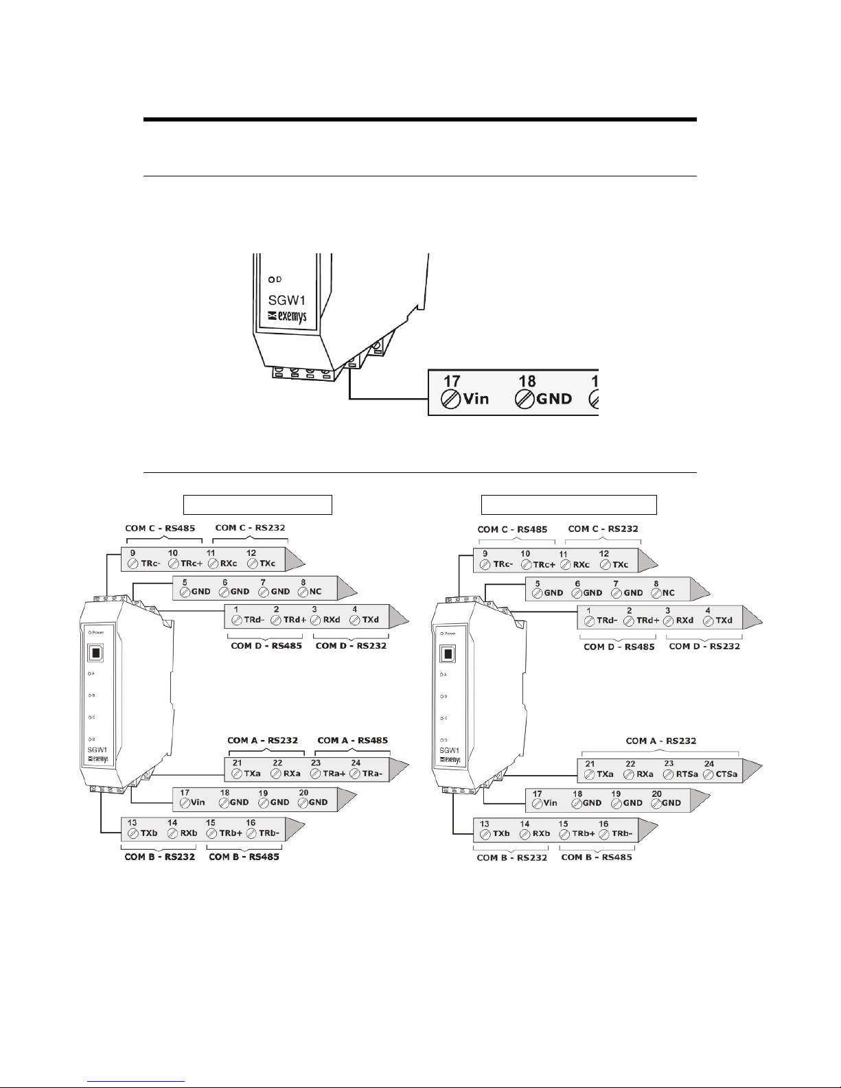
2.2 Connections
SGW1-4B0
4B04B0
4B0----00
0000
00-IA3-MMP SGW1-13B0
13B013B0
13B0----00
0000
00-IA3-MMP-CF
CFCF
CF
RS232 ports are DTE type. That is, it is transmitted through the TX terminal and is received by
the RX terminal. If you want to connect another DTE device you must cross the terminals Tx and
Rx.

SGW1-IA3-MMP – Modbus Multiplexer Exemys
www.exemys.com SGW1-IA3-MMP User’s Manual Rev. 1 7
2.3 LED indicators
The SGW1-IA3-MMP has five indicator LEDs. One of them indicates that the device is
energized (Power). While the other four are each linked to their serial port and shows the
state of communications.
 Loading...