

Page 1

RMS2-AI-IA3 Analog Variables Acquisition Module – User’s Manual Exemys
www.exemys.com Rev. 2 1
Page 2

RMS2-AI-IA3 Analog Variables Acquisition Module – User’s Manual Exemys
Exemys products are constantly evolving to meet the needs of our customers. For this reason,
the specifications and capabilities are subject to change without notice.
Find updates at www.exemys.com
Copyright © Exemys, 2007. All rights reserved.
www.exemys.com Rev. 2 2
Page 3

INDEX
RMS2-AI-IA3 Analog Variables Acquisition Module – User’s Manual Exemys
1111 INTRODUCTION
1.1
1.1 PPPPurpose of the manual
1.11.1
1.2
1.2 Product Overview
1.21.2
1.3
1.3 Order numbers
1.31.3
1.4
1.4 Technical Specifications
1.41.4
2222 INSTALLATION
2.1
2.1 Power Input Connection
2.12.1
2.2
2.2 Connections and term
2.22.2
2.3
2.3 LEDs Indicators
2.32.3
3333 Configuration
3.1
3.1 Serial port configuration
3.13.1
3.2
3.2 Inputs Configuration
3.23.2
3.3
3.3 Advanced Configuration
3.33.3
INTRODUCTION ________________________________
INTRODUCTIONINTRODUCTION
urpose of the manual ________________________________
urpose of the manualurpose of the manual
Product Overview ________________________________
Product OverviewProduct Overview
Order numbers ________________________________
Order numbersOrder numbers
Technical Specifications ________________________________
Technical SpecificationsTechnical Specifications
INSTALLATION ________________________________
INSTALLATIONINSTALLATION
Power Input Connection ________________________________
Power Input ConnectionPower Input Connection
Connections and terminals
Connections and termConnections and term
2.2.1 Analog inputs wiring 7
2.2.2 RS232 serial port wiring 8
2.2.3 RS485 serial port connection 8
LEDs Indicators ________________________________
LEDs IndicatorsLEDs Indicators
Configuration ________________________________
ConfigurationConfiguration
Serial port configuration ________________________________
Serial port configurationSerial port configuration
Inputs Configuration ________________________________
Inputs ConfigurationInputs Configuration
3.2.1 Scaling Configuration. 11
Advanced Configuration ________________________________
Advanced ConfigurationAdvanced Configuration
_____________________________________________________
________________________________________________________________
________________________________________________
________________________________________________________________
____________________________________________________
________________________________________________________________
______________________________________________________
________________________________________________________________
_______________________________________________
________________________________________________________________
______________________________________________________
________________________________________________________________
_______________________________________________
________________________________________________________________
inals ________________________________
_____________________________________________
inalsinals
________________________________________________________________
_____________________________________________________
________________________________________________________________
______________________________________________________
________________________________________________________________
______________________________________________
________________________________________________________________
________________________________________________
________________________________________________________________
______________________________________________
________________________________________________________________
_____________________ 4444
__________________________________________
________________ 4444
________________________________
____________________ 4444
________________________________________
______________________ 5555
____________________________________________
_______________ 5555
______________________________
______________________ 6666
____________________________________________
_______________ 6666
______________________________
_____________ 6666
__________________________
_____________________ 8888
__________________________________________
______________________ 9999
____________________________________________
______________ 10
____________________________
________________ 11
________________________________
______________ 12
____________________________
10
1010
11
1111
12
1212
3.4
3.4 Other Configuration Items
3.43.4
4444 Modbus Communication
4.1
4.1 Modbus Registers
4.14.1
A. FACTORY SETTINGS
A. FACTORY SETTINGS 15
A. FACTORY SETTINGSA. FACTORY SETTINGS
B. DIN RAIL MOUNTING
B. DIN RAIL MOUNTING 16
B. DIN RAIL MOUNTINGB. DIN RAIL MOUNTING
Other Configuration Items ________________________________
Other Configuration ItemsOther Configuration Items
Modbus Communication ________________________________
Modbus CommunicationModbus Communication
Modbus Registers ________________________________
Modbus RegistersModbus Registers
__________________________________________________
________________________________________________________________
____________________________________________
________________________________________________________________
_____________________________________________
________________________________________________________________
__________________ 14
____________________________________
____________ 13
________________________
_____________ 14
__________________________
13
1313
14
1414
14
1414
15
1515
16
1616
www.exemys.com Rev. 2 3
Page 4
RMS2-AI-IA3 Analog Variables Acquisition Module – User’s Manual Exemys
BPS Bits per second
PC Personal Computer
GND Ground (Reference)
1111 INTRODUCTION
INTRODUCTION
INTRODUCTIONINTRODUCTION
1.1
1.1 PPPPurpose
1.11.1
urpose oooof th
urpose urpose
f theeee manual
f thf th
manual
manualmanual
This manual provides instructions for easy and quick installation and operation of the
RMS2-AI-IA3 analog module. The manual starts with a general description of the product,
and then provides instructions for the correct hardware installation. Configuration and
operation of the device is detailed below.
Acronym Description
1.2
1.2 Product
Product Overview
1.21.2
Product Product
Overview
OverviewOverview
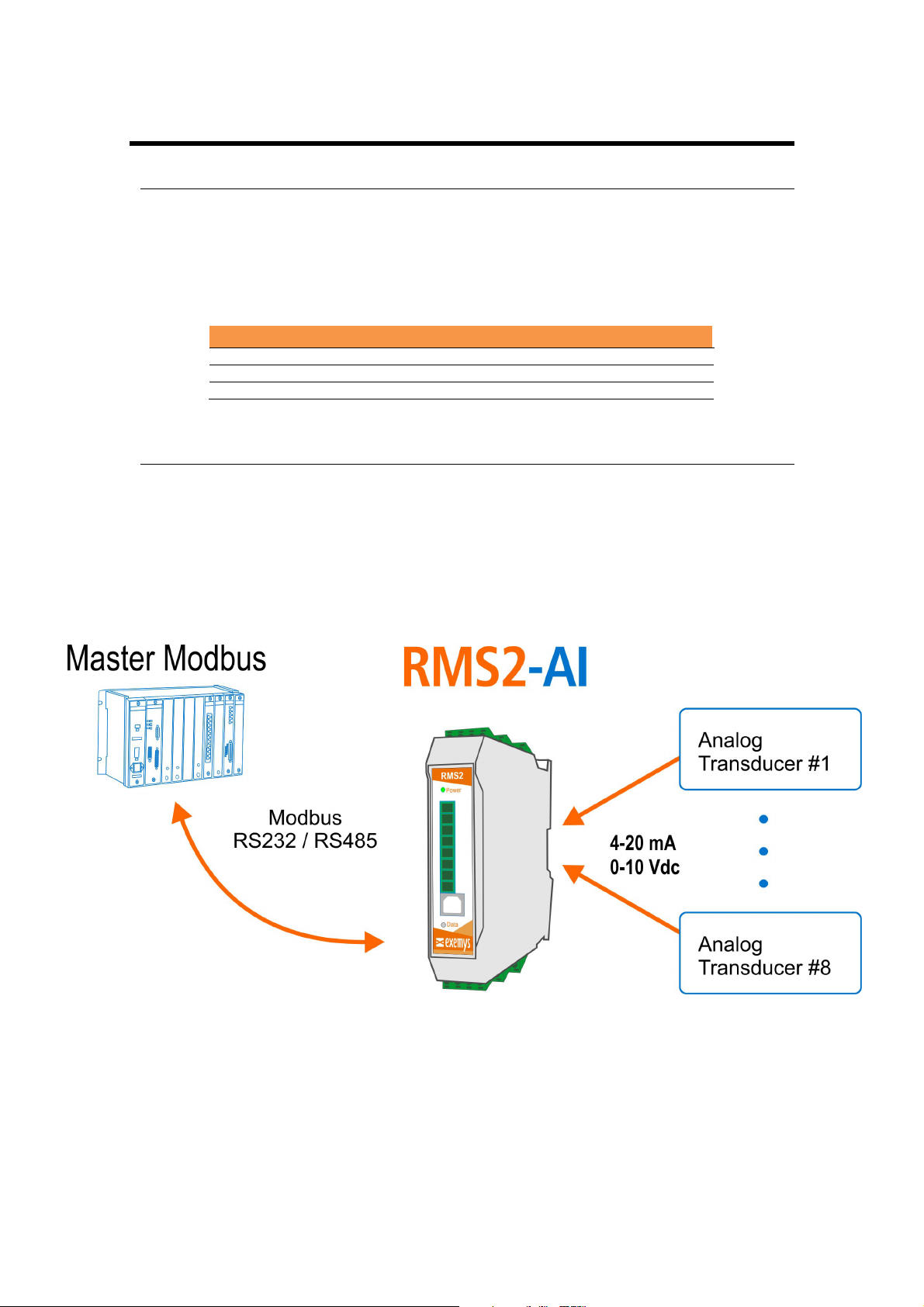
RMS2-AI-IA3 acquisition module is a complete interface for your analog sensors, because it
allows to monitor and supervise analog devices whose output is 4-20 mA current loops or 010V voltage range. This device works in differential mode, which means that it measures the
difference between the absolute values of two signals.
www.exemys.com Rev. 2 4
Page 5

RMS2-AI-IA3 Analog Variables Acquisition Module – User’s Manual Exemys
1.3
1.3 Order
Order numbers
1.31.3
Order Order
numbers
numbersnumbers
Product order numbers are the following:
Code number Description
RMS2-AI-110-00-80-IA3-MB
1.4
1.4 Technical Specifications
Technical Specifications
1.41.4
Technical SpecificationsTechnical Specifications
Technical specifications
Communication p
Communication protocols
Communication pCommunication p
Analog Inputs
Analog Inputs
Analog InputsAnalog Inputs
Input resolution
Input resolution
Input resolutionInput resolution
USB
USB port
port
USBUSB
portport
Serial
Serial Protocol
Protocol
Serial Serial
ProtocolProtocol
Serial
Serial Port
Port
SerialSerial
PortPort
Indica
Indicators
tors
IndicaIndica
torstors
rotocols
rotocolsrotocols
(1)serial port RS-232 / RS-485 optoisolated
(8) 4-20 mA / 0-10V Inputs
Modbus RTU, Modbus ASCII.
0-10V / 4-20mA (Zi = 62Ω).
12 bits
1 USB port type B, for device configuration
Modbus RTU/ASCII
1 RS-232 + 1RS-485optoisolatedwith plug-in terminals
Power LED
Data LED
Measurements
Measurements
MeasurementsMeasurements
Power
Power input
Power Power
Average consumption
Average consumption
Average consumptionAverage consumption
Temperatur
Temperatureeee
TemperaturTemperatur
Warranty
Warranty
WarrantyWarranty
input
inputinput
100 mm x 22,5 mm x 112 mm (High x Width x Depth).
10 to 30 V.
12 Vdc – 50mA / 24 Vdc – 30mA.
Operation Temperature: -15 °Cto 65 °C.
Storage Temperature: -40 °Cto 75 °C.
1 year.
Technical Support included
www.exemys.com Rev. 2 5
Page 6
RMS2-AI-IA3 Analog Variables Acquisition Module – User’s Manual Exemys
2222 INSTALLATION
INSTALLATION
INSTALLATIONINSTALLATION
2.1
2.1 Power
Power Input
2.12.1
Power Power
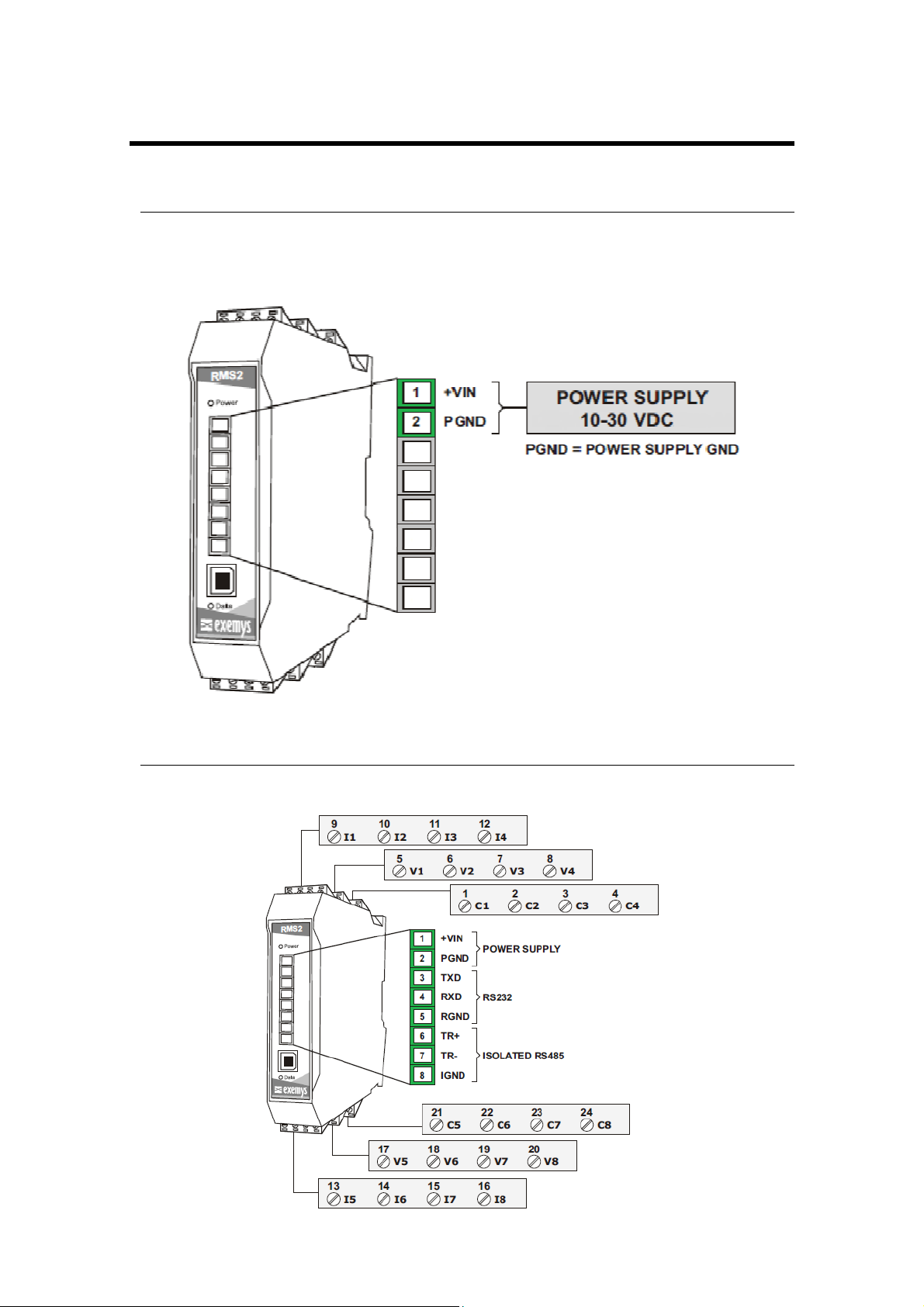
RMS2-AI-IA3 allows a power input from +10 to 30 VDC. Positive power supply must be
connected to the terminal N° 1 and negative power supply to terminal N° 2 as can be shown
in the following figure:
Input Connection
Input Input
Connection
ConnectionConnection
2.2
2.2 Connections and terminals
Connections and terminals
2.22.2
Connections and terminalsConnections and terminals
Device has 7 plug-in terminals. The function of each terminal is indicated in the following
picture.
www.exemys.com Rev. 2 6
Page 7
RMS2-AI-IA3 Analog Variables Acquisition Module – User’s Manual Exemys
2.2.1
2.2.1 Analog inputs
2.2.12.2.1
Analog inputs wiring
Analog inputs Analog inputs
2.2.1.1
2.2.1.1 Voltage
2.2.1.12.2.1.1
Voltage input
Voltage Voltage
wiring
wiringwiring
input wiring
inputinput
wiring ((((0000----10V
wiringwiring
10V))))
10V10V
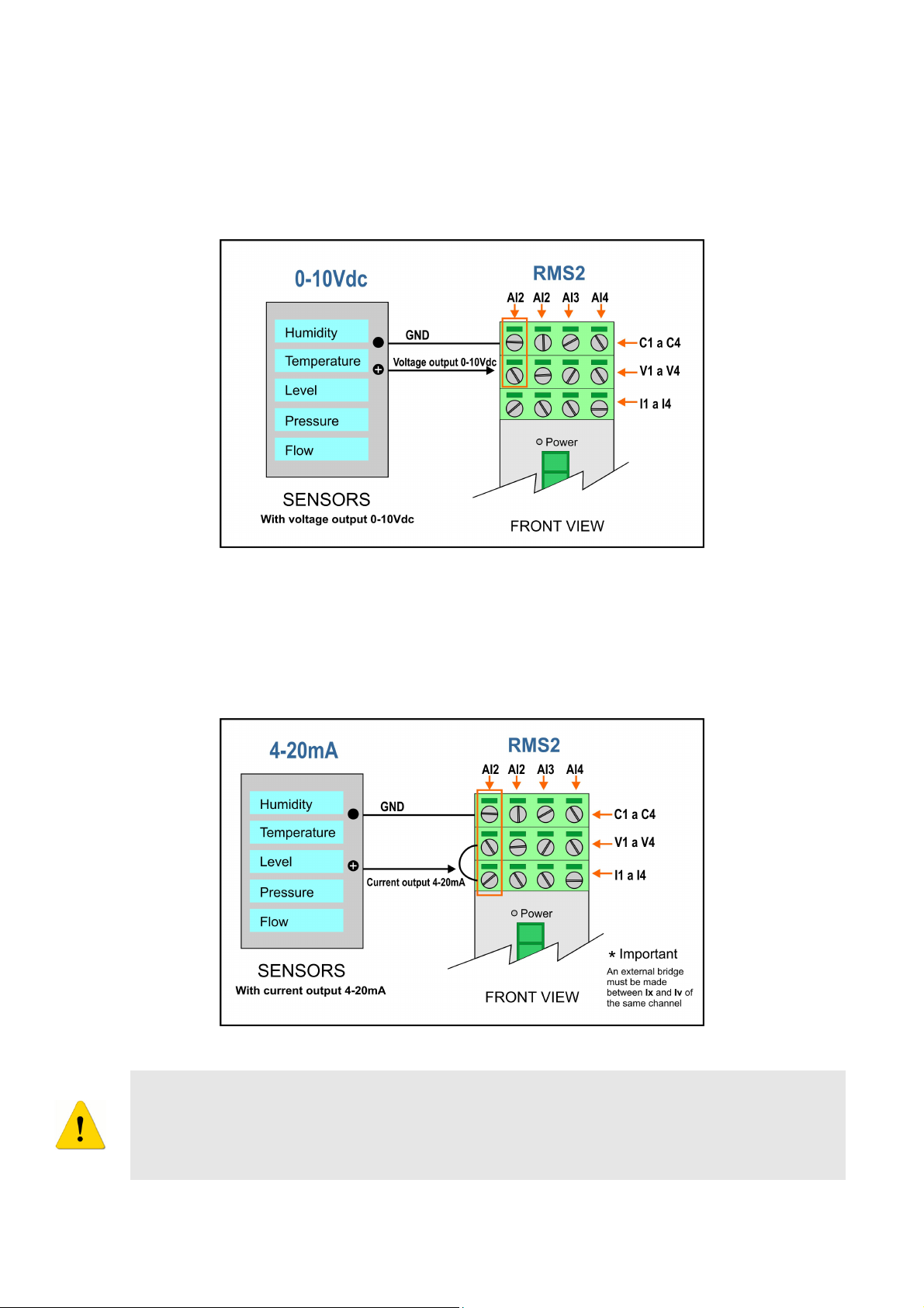
Sensors with voltage output (0-10V) can be connected to the device as shown in the
following figure.
2.2.1.2 Current
Current input
Current Current
input wiring
input input
wiring ((((4444----20mA
wiringwiring
20mA))))
20mA20mA
In this case, sensors with current loop output (4-20mA) can be connected to the
device as shown in the following figure.
The input impedance value of each track is 62Ω.
Do not exceed the signal limit for each case (10 V or 20 mA respectively).
Excessive signal level may cause abnormal operation or permanent damage to the device.
www.exemys.com Rev. 2 7
Page 8

RMS2-AI-IA3 Analog Variables Acquisition Module – User’s Manual Exemys
Power
Data
Description
Switched on
- Energized device
- Flashes turning off
Data Transmission or reception
Flashes alternately with
Flashes alternately with the
Critical failure. Contact technical
2.2.2
2.2.2 RS232
2.2.22.2.2
RS232 serial port
RS232RS232
serial port wiring
serial port serial port
wiring
wiringwiring
To connect the device RS232 serial port to PC serial port or any other serial device, it must be
connected as can be shown in the following figure. You should consider RMS2-AI-IA3 is a
DTE device, which means it must cross wire with those of the PC.
2.2.3
2.2.3 RS
2.2.32.2.3
RS485
485 serial port connection
RSRS
serial port connection
485485
serial port connectionserial port connection
To connect the device RS485 serial port to PC serial port or any other serial device, it must be
connected as can be shown in the following figure.
2.3
2.3 LED
LEDs Indicators
2.32.3
s Indicators
LEDLED
s Indicatorss Indicators
RMS2-AI-IA3has two LEDsindicators.Power LED indicates that device is energized, whereas
Data LED shows activity of RS232 / RS485 port.
the Data LED
Power LED
support.
www.exemys.com Rev. 2 8
Page 9

RMS2-AI-IA3 Analog Variables Acquisition Module – User’s Manual Exemys
3333 Configuration
RMS2-AI-IA3 configuration is done through a command console connecting the device to a
USB port on the PC.
To access the command console, you must connect the RMS2-AI-IA3 to a USB port on a PC
and you must install an Exemys serial terminal program, named
Download the USB driver:
http://www.exemys.com/rmsrmdriver
Download the Exemys Console:
http://www.exemys.com/console
Once the driver and the serial terminal program are installed, connect the RMS2-AI-IA3 to a
USB port on the PC and execute the
Exemys Console
.
1. Click on Connection -> USB, it will open a window with the description of all the
Exemys products with USB port. Select with double click the product you want to set.
Exemys Console.
2. Type CFG and press ENTER or press the CFG button. RMS2-AI-IA3 will display
welcome message on the configuration command console.
www.exemys.com Rev. 2 9
Page 10

RMS2-AI-IA3 Analog Variables Acquisition Module – User’s Manual Exemys
Op
tion
Descrip
tion
3. Type the menu or submenu number to which you want to access and edit its
parameters with the proposed values.
3.1 Serial port configuration
1->1
Baud Rate
(1200|…|115200)
1->2
Data Bits
(7|8)
1->3
Parity
(N|E|O)
1->4
Stop Bits
(1|2)
1->5
Modbus
Mode(RTU|ASCII)
Setting the BaudRate.
Values: 1200, 2400, 4800, 9600, 19200, 38400, 57600, 115200.
Example: 1->1->4 (Serial Port->Baud Rate->1200)
Setting the Data Bits
Values: 7 Bits, 8 Bits.
Example: 1->2->1 (Serial Port->Data Bits->7 Bits)
Setting the Parity
Values: None, Odd, Even.
Example: 1->3->3 (Serial Port->Parity->ODD)
Setting the Stop Bits
Values: 1,2
Example: 1->4->1 (Serial Port->Stop Bits->1)
Setting the Modbus Mode
Values: RTU, ASCII.
Example: 1->5->1 (Serial Port->Modbus Mode->RTU)
www.exemys.com Rev. 2 10
Page 11

RMS2-AI-IA3 Analog Variables Acquisition Module – User’s Manual Exemys
Op
tion
Descrip
tion
Op
tion
Descrip
tion
3.2 Inputs Configuration
1->1...8->1
Input Type
(4-20mA| 0-10V)
1->1...8->2
Average
(1|…|100)
1->1...8->3
Scaling
(X0 | Y0 | X1 | Y1)
Setting the analog input type
Values: Voltage 0-10 V, Current Loop 4-20 mA.
Example:
2->1->1->2 (Inputs->Input Nº1->Input Type ->0-10V)
Setting the number of samples that are taken to make an average of readings. This is
the value shown when the input is monitored.
Values: 1, 5, 10, 20, 50, 100.
Example:
2->2->2->20 (Inputs->Input Nº2->Average->20)
RME2-AI-IA3 can convert the measured value to a scaled value.
For example, you can convert a signal from a temperature transducer with
4-20mA output to a reading of -100 to 500 degrees Celsius; for this, you must set the
2 points to scale, in this way, device applies the equation of a line given that you
know two points it passes through.
3.2.1
3.2.1 Scaling Configuration.
3.2.13.2.1
Scaling Configuration.
Scaling Configuration.Scaling Configuration.
The value YMIN will be the desired minimum output value.
1->1...8->3->1
Y0
(-32767| 32767)
Values: -32767…32767.
Example:
2->5->3->1->-100(Inputs->Input Nº5->Scaling->YMIN->-100)
The value YMAX will be the desired maximum output value.
1->1...8->3->2
Y1
(-32767| 32767)
Values: -32767…32767.
Example:
2->5->3->2->500 (Inputs->Input Nº5->Scaling->YMAX->500)
Next, we will post an example about it was explained previously:
It’s necessary to convert a signal from a temperature transducer with 4-20mA output to a
reading of -100 to 500 degrees Celsius. For this, the output values would be
YMIN = -100 and YMAX= 500.
www.exemys.com Rev. 2 11
Page 12

RMS2-AI-IA3 Analog Variables Acquisition Module – User’s Manual Exemys
Op
tion
Descrip
tion
3.3 Advanced Configuration
1->1
Modbus Slave ID
(1…254)
3->2
CSV Monitor
(0|1)
Setting the internal Modbus Slave ID to access to the data transfer memory
Values: 1…254.
Example: 3->1->50(Advanced->Modbus Slave ID->50)
Enables/Disables the text monitor option
Values= Enabled / Disabled
Example: 3->2->1 (Advanced->CSV Monitor->Enabled)
After enabling CSV monitor you must choose option ‘E’ on the main menu for it to start
working.
While it’s enabled the device will send once a second the scaled value of the 8 analog inputs
on the USB port. It will be text formatted and separated with commas.
Once enabled, it will be enabled even after turning the device off. To enter configuration
mode again press ESC or ENTER and type CFG and ENTER
www.exemys.com Rev. 2 12
Page 13

RMS2-AI-IA3 Analog Variables Acquisition Module – User’s Manual Exemys
Showing the current device measurements, represented in 3
3.4 Other Configuration Items
Option Description
A
Show Configuration
B
Show Monitor
C
Restart
Listing the current device configuration.
different types of values, detailed below:
Analog Value
Analog Value: Value in Ampere or Volt according to each of the
Analog ValueAnalog Value
inputs configured.
Range 0-10 V or 4-20 mA.
Scaled Value
Scaled Value: In this field you see the value calculated according to
Scaled ValueScaled Value
the scaling configuration.
A/D Convert Value
A/D Convert Value: Analog digital converter counts for each of the
A/D Convert ValueA/D Convert Value
eight inputs.
Restart the device.
D
Factory Reset
E
Exit
Reset to the factory setting
This command must be typed 2 times to begin working.
Ends the configuration mode.
www.exemys.com Rev. 2 13
Page 14

RMS2-AI-IA3 Analog Variables Acquisition Module – User’s Manual Exemys
40001
to 40008
Anal
og Value
(x 100).
Current inputs status (This field that indicates the status of each
40017 to 40024
Scaling Value
.
Analog digital converter counts
Input type
.
Average
.
Scaling YMIN value for all the inputs
Scaling YMAX value for all the inputs
4 Modbus Communication
4.1 Modbus Registers
Each input has a register in the Modbus Holding Registers area. In this way, once the
communication is established, the data is transferred transparently from the analog inputs to
the corresponding Modbus address.
Holding Registers presented below are read o
Modbus TCP Registers Description
analog input configured in current).
0: Normal.
40009 to 40016
1: Below 4mA
2: Above 20mA
Note: these registers are 0 when the inputs are configured in
voltage.
40025 to 40032
0 for 0V and 4000 for 10V.
800 for 4mA and 4000 for 20mA.
40201 to 40208
0000: Current 4-20mA.
1111: Voltage 0-10V.
read only
nly.
read oread o
nlynly
40209 to 40216
1, 5, 10, 20, 50, 100 ->Number of samples to average.
40217 to 40224
40225 to 40232
www.exemys.com Rev. 2 14
(values from - 32.767 to 32.767)
(values from - 32.767 to 32.767)
Page 15

RMS2-AI-IA3 Analog Variables Acquisition Module – User’s Manual Exemys
Par
ameters
Value
Serial Port
Serial PortSerial Port
Serial Port
AAAA
Baud Rate.
9600
bps
Data
Bits 8
Parity. NO
Stop B
its 1
Modbus
Mode
. Modbus
RTU
Type
. 4-20 mA
Average
. 5
Y
MIN 400
YMAX
2000
Ot
OtOt
Ot
hers
hershers
hers
Internal Memory I
D.
240
A.Factory Settings
INPUTS
INPUTS x 8
INPUTSINPUTS
x 8
x 8x 8
Configura
Configuration
ConfiguraConfigura
tion
tiontion
www.exemys.com Rev. 2 15
Page 16

RMS2-AI-IA3 Analog Variables Acquisition Module – User’s Manual Exemys
B.DIN Rail Mounting
Device can be mounted on a DIN rail. To assembly the module to the rail, make the upper
side of the device fit the DIN rail and then push gently until you hear a Click! As shown in the
figure.
To disassemble the device of the rail DIN, pull down the metallic clip and then remove it as
shown in the figure.
www.exemys.com Rev. 2 16
 Loading...