

Page 1
EXLs3 rev09-051114
EXLs3
Miniature Wireless
Inertial Measurement Unit
USER GUIDE
(FIRMWARE REV. 6.26)
Page 2

2
Table of contents
1. GENERAL DESCRIPTION .................................................... 3
2. FEATURES ............................................................................ 3
3. HARDWARE OVERVIEW ...................................................... 4
4. INTERNAL BLOCK DIAGRAM ............................................. 6
5. REFERENCE SYSTEM .......................................................... 7
6. MEASUREMENT UNITS........................................................ 8
7. BLUETOOTH SETUP ............................................................ 9
8. COMUNICATION PROTOCOL ............................................ 13
8.1. BASIC COMMANDS ............................................................ 13
8.2. PACKET DATA TYPES ........................................................ 13
8.3. CONFIGURATION COMMANDS ............................................ 16
8.4. CONFIGURATION REGISTERS ............................................. 16
8.5. CONFIGURATION PARAMETER ACCESS .............................. 19
8.6. REAL TIME CLOCK CONFIGURATION ................................... 21
8.7. OTHER COMMANDS ........................................................... 22
APPENDIX A. FIRMWARE UPDATE ..................................... 23
LEGACY FUNCTIONS ............................................................. 26
Page 3

3
EXLs3
Miniature Wireless Inertial Measurement Unit
1. GENERAL DESCRIPTION
The EXLs3 is a miniaturized electronic device with the function of real-time Inertial Measurement Unit
(IMU).
It features a complete MEMS sensor set, which is composed of a tri-axial accelerometer, gyroscope
and compass, a 32-bit Cortex microprocessor for data processing and a Bluetooth radio to send real-
time data.
The unit can be used for real-time motion measurement and transmission in particular in the medical field
as a wearable device for biomechanical analysis, such as posture assessment, rehabilitation, gait
monitoring, joints’ functionality analysis, activity monitoring, etc.
The Bluetooth™ radio allows easy interfacing to a wide range of devices (PC, Tablets, Smartphones)
without the need of additional hardware so that data can be transmitted wirelessly up to 10 meters.
The unit is also equipped with an embedded 1 GB flash drive which allows data logging to CSV files
and USB interface for file transfer.
The on board 32-bit CPU provide algorithms for orientation estimation with Kalman filtering in order to
give high quality measurement.
The integrated rechargeable Litium battery allows continuous data acquisition and streaming up to 3
hours and can be recharged by means of a dedicated docking station.
2. FEATURES
Module size 54 mm x 33 mm x 14 mm
Module weight 22 g
32-bit MCU, Cortex-M3 @72 MHz
3-axis accelerometer with selectable full-scale range (±2 / ±4 / ±8 / ±16 g).
3-axis gyroscope with selectable full-scale range (±250 / ±500 / ±1000 / ±2000 dps)
3-axis magnetometer
Orientation estimation with Kalman filtering and quaternion output.
Sampling rate up to 200 Hz for raw data and 100 Hz for orientation data.
Various data packet format available
Bluetooth™ 2.1 class 1.
Up to 7 nodes at the same time can stream data to the same host.
1GB Flash Memory (USB Mass Storage) for data storage
Docking station with micro-USB connector for battery recharging and log-file downloading.
Battery operating time 3h
Firmware upgradable by means of bluetooth connection.
Page 4
4
3. HARDWARE OVERVIEW
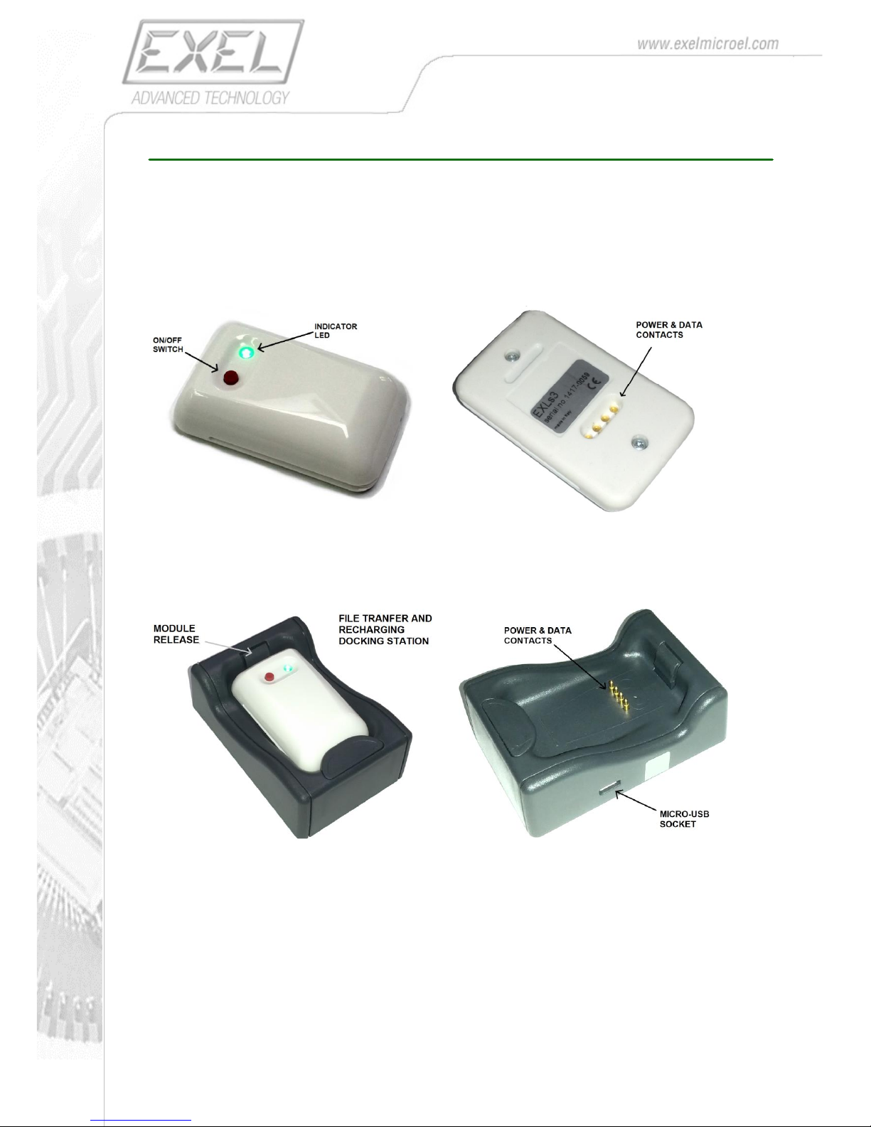
On the front side of the IMU the ON/OFF button and an indicator LED are located.
In order to switch-on the device, press shortly the button. The LED lights green.
To switch-off the IMU press and hold the button for two seconds, until the LED turns-off.
In addition, the IMU turns-off automatically after 10 minute of inactivity.
When the battery reaches a low voltage the LED starts blinking red.
On the back side 4 golden contacts are present in order to allow communication with the docking station
for battery recharging and data download.
The Docking-station allows the sensor to be interfaced to a PC via USB cable, for battery recharging
and data-log file transfer.
The IMU must be properly placed in the docking station as shown in the above picture.
For battery recharging is alternatively possible to connect the docking station to a standard 5V power
supply equipped with micro-USB connector.
The current required to recharge the battery is 250 mA.
When the battery is being charged the EXLs3’s indicator LED turns red.
When the battery is fully charged the LED turns green.
By connecting the docking-station to a PC it is possible to access the IMU’s internal storage flash disk, in
order to retrieve data-log files.
Page 5
5
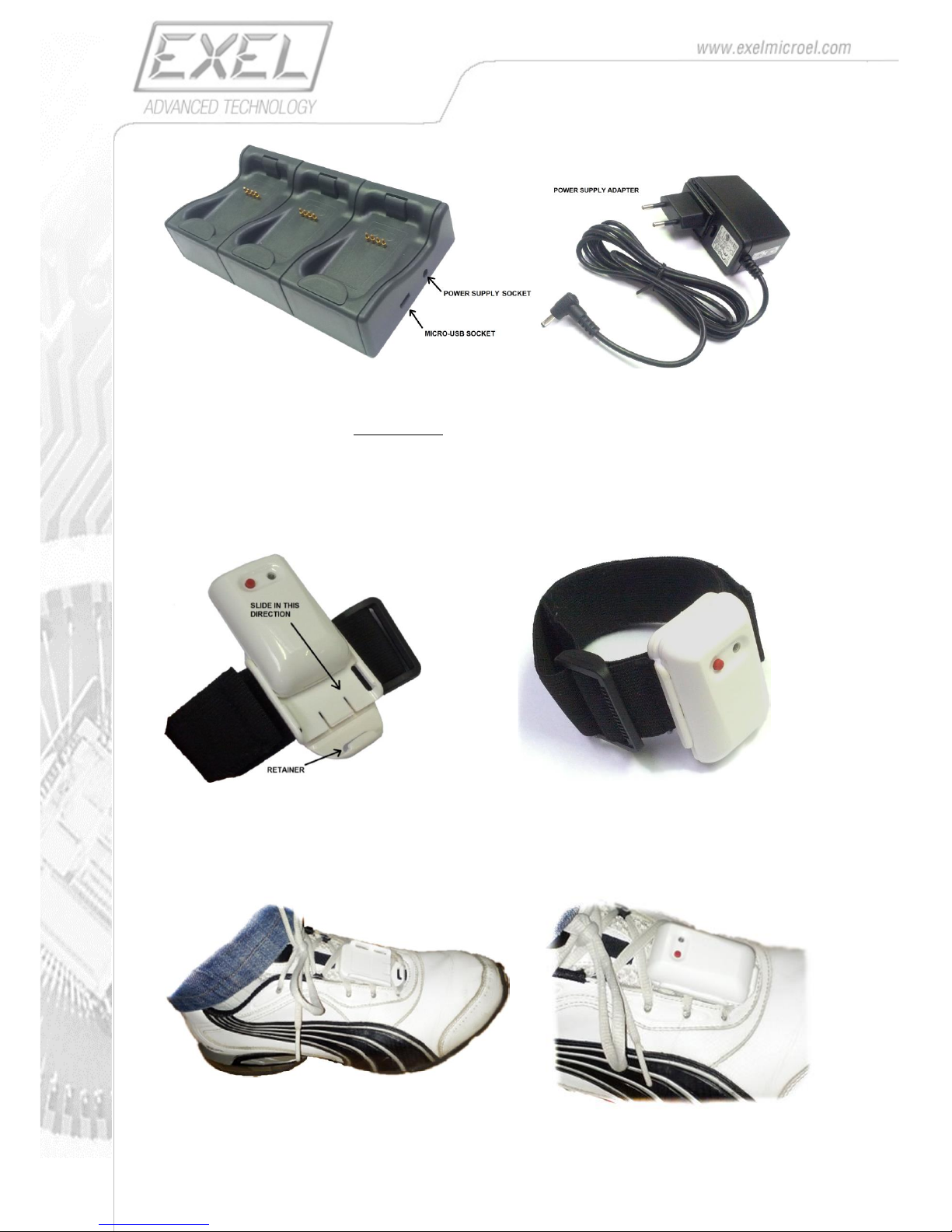
The Multiple Docking-Station allows more units to be recharged at the same time. It also acts as USB
hub which allows more units to be seen as multiple distinct flash disks where log files can be found.
The multiple docking-station must be used with the provided Power Supply Adapter, otherwise neither
battery recharging nor USB hub will work.
The IMU is provided with a special holder which allows easy fixing to a Velcro-strap or similar.
The IMU must be placed as shown in the following picture, by sliding it in the holder gently until the
body hooks in the retainer, making sure the holder’s lateral rails fit in the respective sensor’s slots.
In case of gait analysis the holder can be used to hook the IMU to shoes-laces, as shown in the
following picture.
Page 6
6
4. INTERNAL BLOCK DIAGRAM
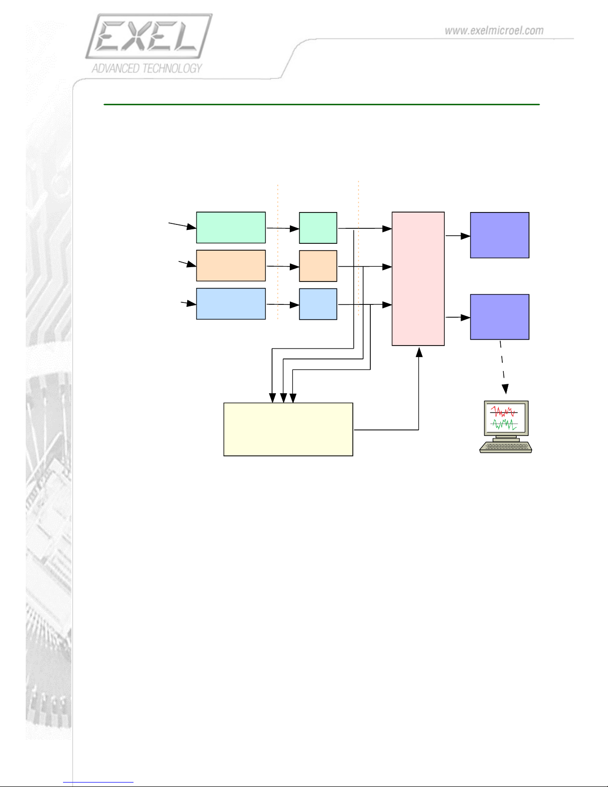
The following picture shows in a simplified form the internal logic of the EXLs3 unit.
The task of the unit is to measure in real-time the linear acceleration and the angular velocity at which
the unit itself is subjected (inertial measurements).
The unit can at the same time measure the magnitude of the surrounding magnetic field.
All measurements are performed by tri-axial sensors, so both magnitude and vector direction are
acquired.
After the compensation of sensor’s raw data (i.e. offset and gain error removal), data and are processed
in order to calculate the orientation of the unit related to a earth reference frame in real-time.
Compensated inertial data together with Orientation data are packed and sent wirelessly to the host PC a
the desired sampling rate.
The produced stream can also be saved in the internal flash drive, as standard CSV file, in order to be
retrieved afterwards via USB connection for off-line post-processing and/or analysis.
3-axis
Digital
Accelerometer
3-axis
Digital
Gyroscope
3-axis
Digital
Magnetometer
comp
comp
comp
ORIENTATION ESTIMATION
Linear A cceleration
(m/s²)
Angular Speed
(rad/s)
Earth Magnetic
Field (µT)
RAW D ATA COMPENSATED DATA
DATA
PAC KING
AND
TIME-
STAMPING
BLUETOOTH
RADIO
DATA-LOG
ON INTERNAL
DRIVE
(CSV FILE)
HOST PC
Page 7
7
5. REFERENCE SYSTEM
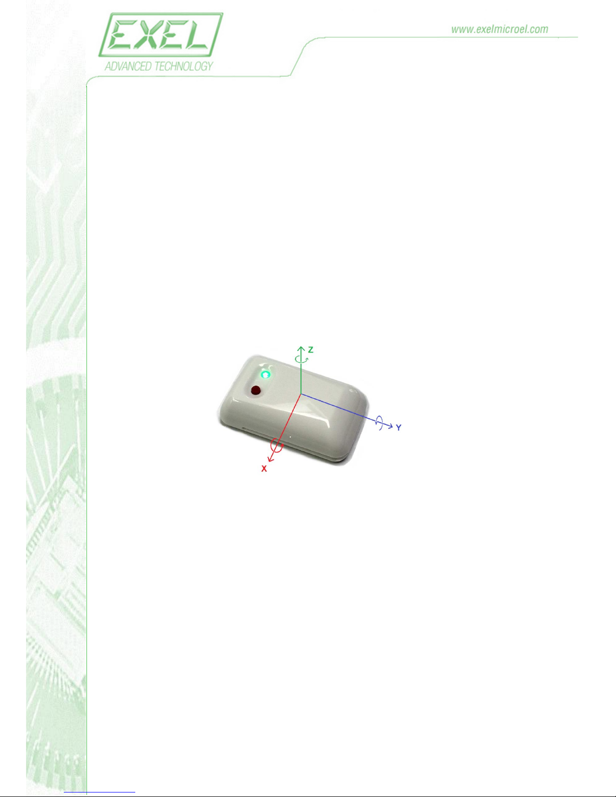
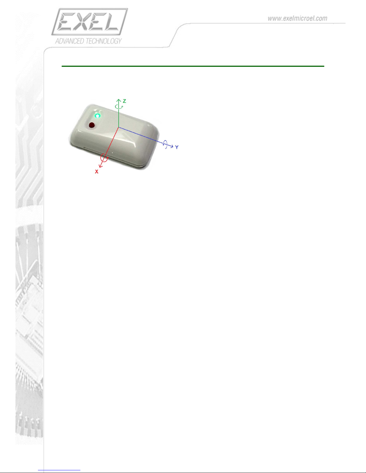
All raw inertial measurements (linear accelerations, angular velocity and earth magnetic field
provided by the unit are referred to the reference system shown below (body frame).
The orientation of the unit in the space is referred to an earth-bound frame where:
X is pointing NORTH
Y is pointing WEST
Z is pointing UPWARDS
The orientation of the sensor is given by a quaternion (q0,q1,q2,q3) representing the rotation of the
unit’s body frame with respect to the earth frame.
Thus when the X axis of the sensor is pointing NORTH and Y axis is pointing WEST the output is the
Identity Quaternion (1,0,0,0).
Page 8
8
6. MEASUREMENT UNITS
Main data returned in real-time by the EXLs3 to the host system are:
Acceleration (AccX, AccX, AccZ)
Angular Velocity (GyrX, GyrY, GyrZ)
Magnetic Field (MagX, MagY, MagZ)
Orientation (Q0, Q1, Q2, Q3)
For the Acceleration and the Angular Velocity you can chose among several full-scale ranges in order to
best fit the specific application requirement.
All data are sent in binary form, so they require conversion to be expressed in standard measurement
units.
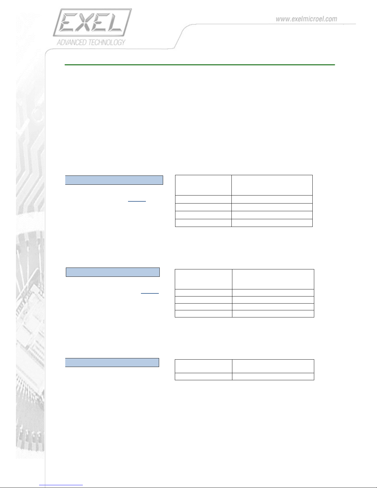
ACCELERATION
a [m/sec2] = Ka
𝐴𝑐𝑐
32768
SELECTED
FULL-SCALE
RANGE
Ka
±2 g
2 x g (19.613 m/sec2)
±4 g
4 x g (39.227 m/sec2)
±8 g
8 x g (78.45 m/sec2 )
±16 g
16 x g (156.91 m/sec2 )
This formula must be applied to each component (AccX, AccY and AccZ) of the acceleration.
ANGULAR VELOCITY
ω[degree/sec] = Kg
𝐺𝑦𝑟
32768
SELECTED
FULL-SCALE
RANGE
Kg
±250 dps
250 dps
±500 dps
500 dps
±1000 dps
1000 dps
±2000 dps
2000 dps
This formula must be applied to each component (GyrX, GyrY and GyrZ) of the angular velocity.
MAGNETIC FIELD
B[uT] = Km 𝑀𝑎𝑔
FULL-SCALE
RANGE
Km
±1200 dps
0.007629 uT
This formula must be applied to each component (MagX, MagY and MagZ) of the angular velocity.
Page 9
9
ORIENTATION
The orientation of the EXLs3 in the space is represented by a unit quaternion (q0, q1 , q2, q3)
representing the rotation of the unit’s body frame with respect to the earth frame.
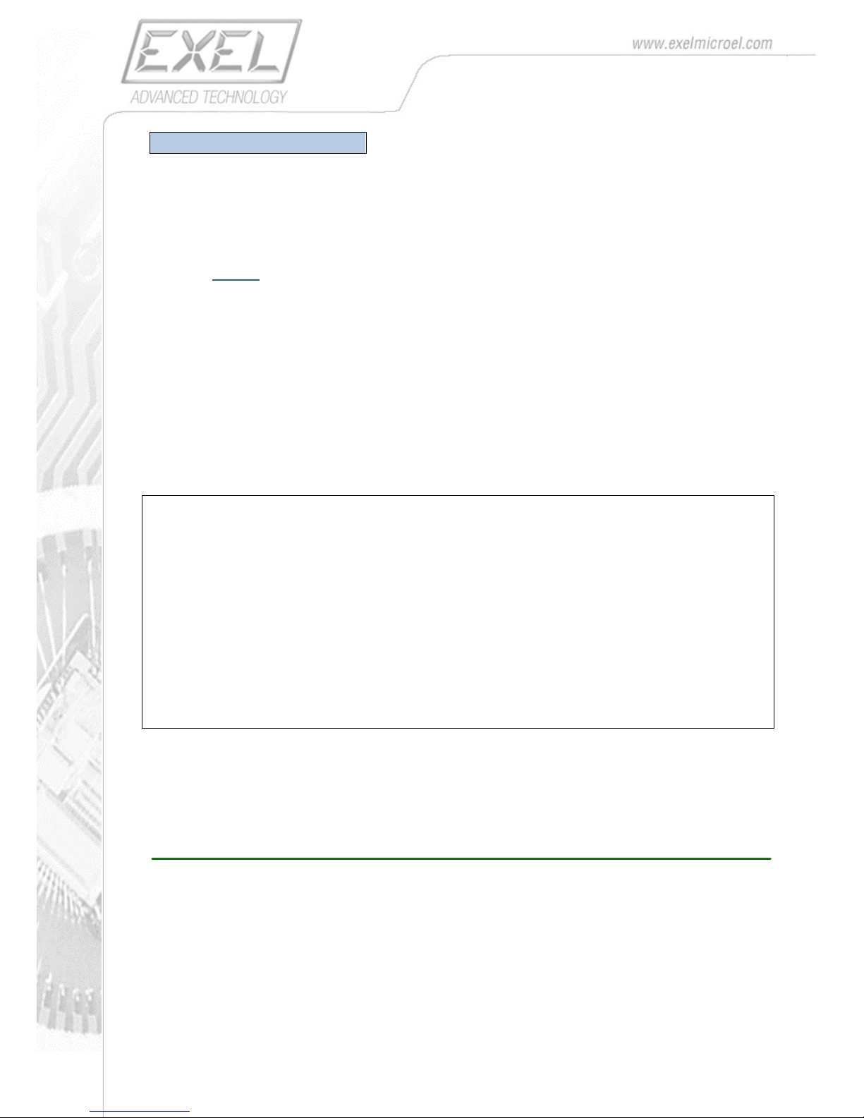
The quaternion’s components returned by the EXLs3 are normalized so that the unity is represented by
the value 16384. So the following formula should be applied:
qn =
𝑄
𝑛
16384
n = 0,1,2 and 3
The rotation of the body-frame is identified by an axis of rotation A and an angle of rotation α around that
axis:
q0 = cos(α / 2)
q1 = Ax sin(α / 2)
q2 = Ay sin(α / 2)
q3 = Az sin(α / 2)
EXAMPLES:
A rotation of +90 degrees around the Z axis (0,0,1) results:
q0 = cos(90 / 2) = 0.7071
q1 = 0 sin(90 / 2) = 0
q2 = 0 sin(90 / 2) = 0
q3 = 1 sin(90 / 2) = 0.7071
A rotation of -90 degrees around the Y axis (0,1,0) results:
q0= cos(-90 / 2) = 0.7071
q1 = 0 sin(-90 / 2) = 0
q2 = 1 sin(-90 / 2) = -0.7071
q3 = 0 sin-(90 / 2) = 0
The Identity Quaternion (1,0,0,0) indicates the unit’s body frame (X-Y-Z) is aligned with the North-West-Up earth-frame.
7. BLUETOOTH SETUP
The communication with the unit is done via bluetooth SPP connection, so you should have a Bluetooth
2.1 internal card or USB Bluetooth dongle properly installed on your host machine.
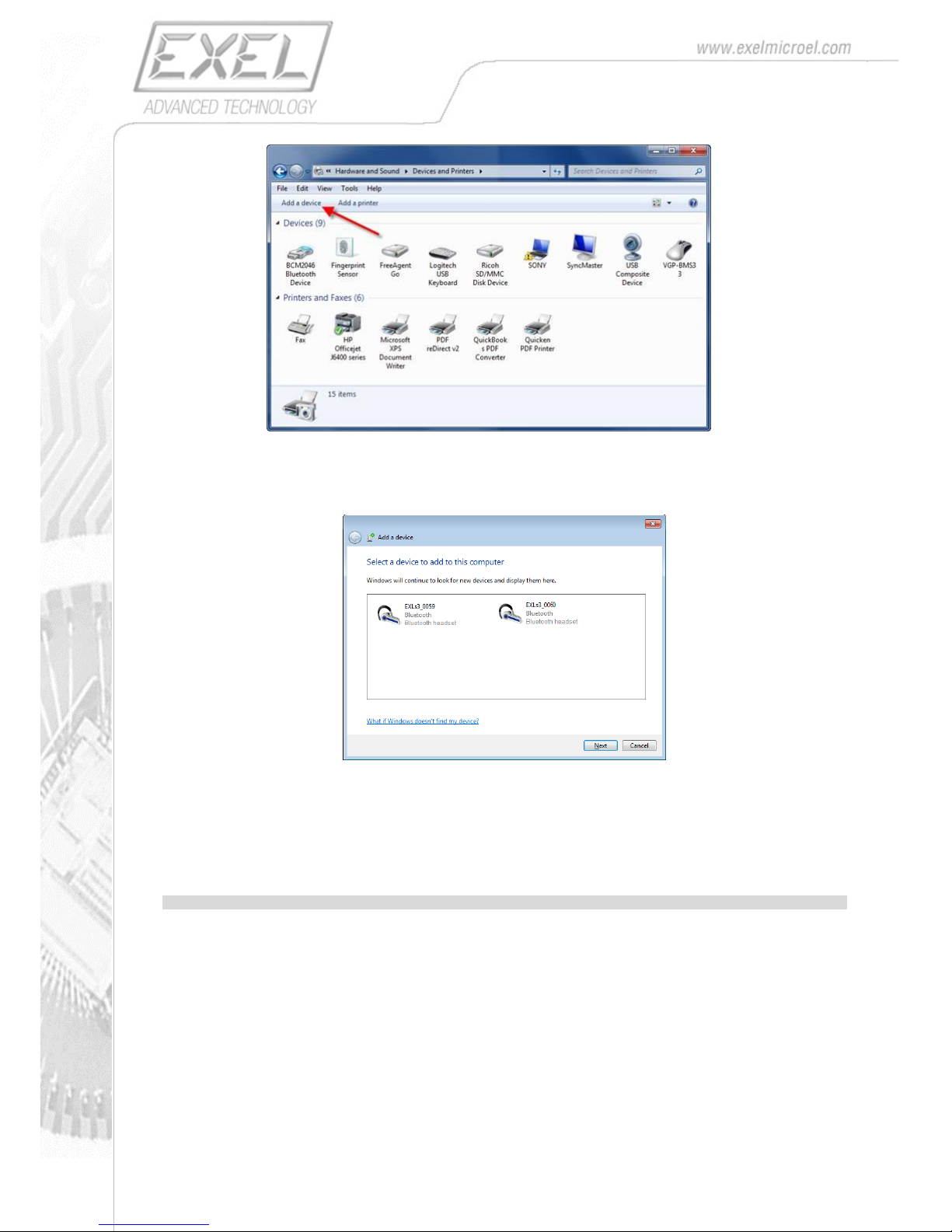
After, you must pair each EXLs3 with the host by going to View Devices and Printers (under Windows 7)
and clicking on Add a device. Note your EXLs3 device(s) must be switched-on in order to be
discoverable by the host.
Page 10
10
After a few seconds (up to 15) you should se a list of the available EXLs3 devices and you can select
the one you want to pair.
After a few seconds (up to 15) you should se a list of the available EXLs3 devices and you can select
the one you want to pair.
Note: for FW rev 6.26+ the EXLs3 is seen as generic Bluetooth device instead of bluetooth headset
Page 11
11
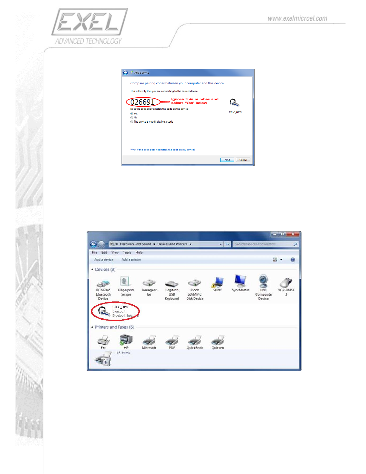
When the following window appear, just ignore the shown code and press Next.
The driver installation starts automatically. During this process you should see at the bottom-right of your
screen a notification of new COM port installation.
Ignore possible message of driver installation error, depending on the extra profiles supported by your
bluetooth dongle).
At the end of the process you should have the EXLs3 device added in the Devices and Printers group:
By double-clicking the EXLs3 device on the window you can access the associated Properties.
Page 12
12
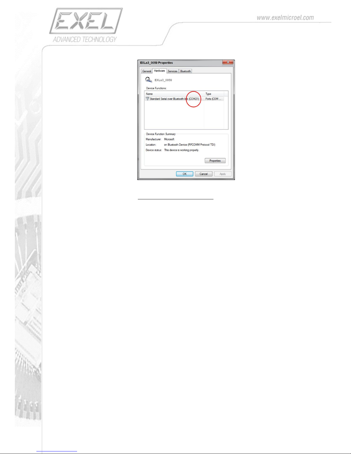
In the Hardware tab, you must take note of the COM number (in the case above COM12) associated
with the Standard Serial over Bluettoth Link function.
The identified COM port is the interface your host system will use to communicate with the EXLs3
device.
Page 13
13
8. COMUNICATION PROTOCOL
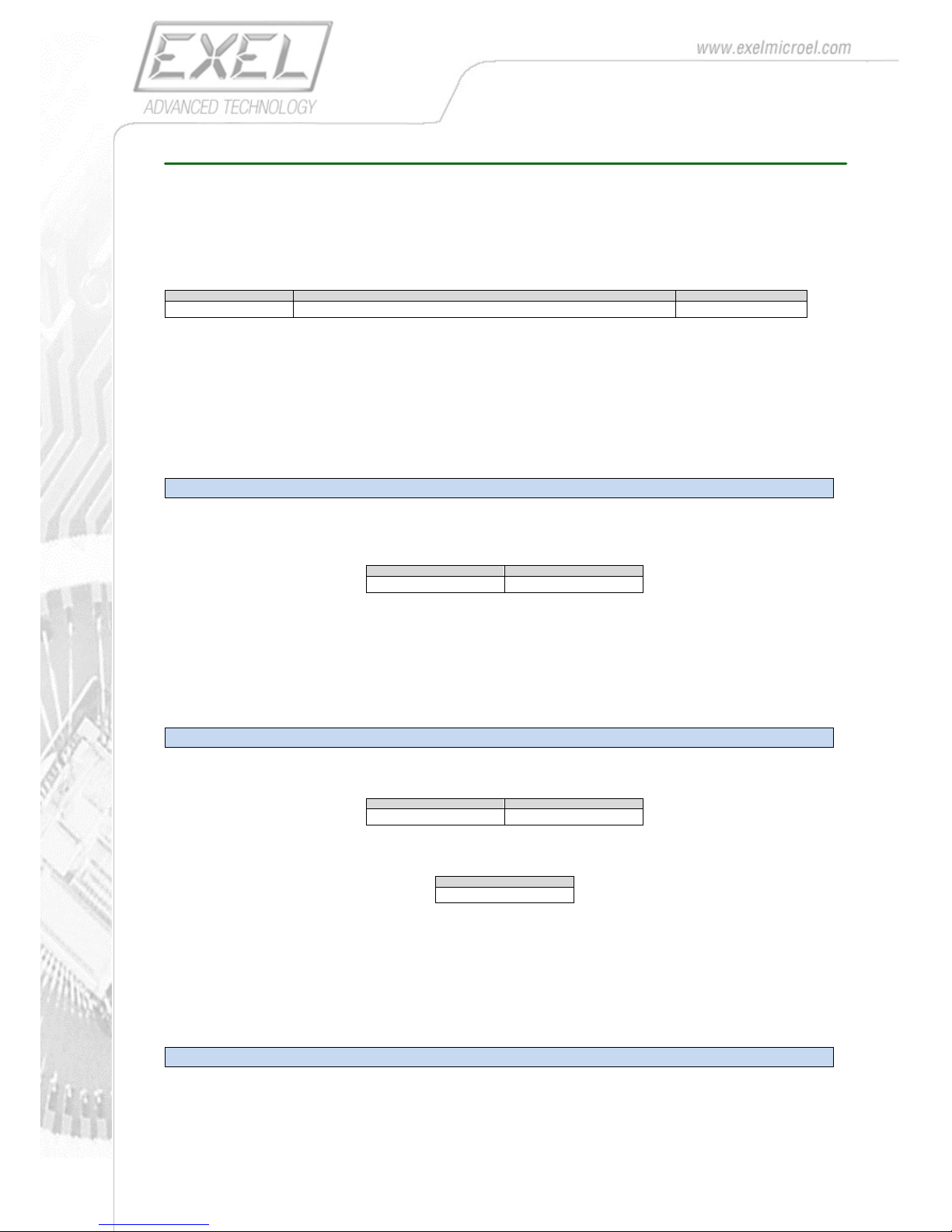
The commands used to interact with the device are based on datagrams sent by the host device via the
serial port profile over Bluetooth. They are in general constituted of an opcode (1 byte) followed by
variable number of parameters (n bytes) and 1 byte checksum, calculated as sum modulo-256 of the
previous n+1 bytes.
Byte0
Byte1 .. byte N
Byte (N + 1)
OPCODE
PARAMETERS
CHECKSUM
If the command is properly recognized by EXLs3 it responds with an ACK byte (0x01).
In case of error it respond with NACK byte (0x00)
8.1. Basic Commands
START_STREAM (0x3D)
Use this command to start real-time streaming of sampled and processed data to the controlling PC.
Byte 0
Byte1
0x3D
0x3D
The sensor starts sending to the host the data sampled in real-time with the format shown in the
paragraph Packet Data Types.
STOP_STREAM
Use this command to stop real-time streaming.
Byte 0
Byte1
0x3A
0x3A
The sensor responds with an acknowledge
Byte0
0x01
8.2. Packet Data Types
When in streaming mode, the EXLs3 unit can send different type of packets, depending on the value of
the PACKET_TYPE parameter (see in the registers description paragraph).
AGMOB_Type (Accelerometer, Gyroscope, Magnetometer, Orientation, vBattery)
This is the most generic packet format, which includes all possible information at the same time.
Page 14
14
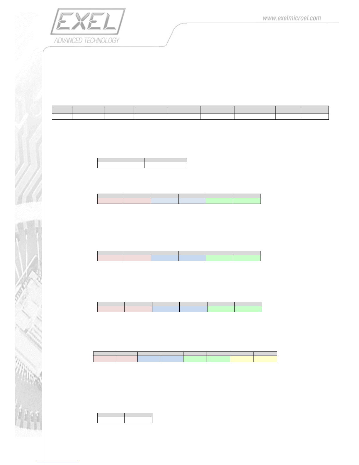
With this packet, the EXLs3 units sends the real-time, the acceleration, the angular velocity and the
magnetic field, as well as the estimated orientation of the unit.
Together are also packed the value of the EXLs3’s battery voltage and a progressive packet counter.
The actual values of acceleration, angular velocity, magnetic field and orientation can be calculated with
the formulas described in paragraph Measurement Units.
Byte0
Byte1
Byte2..Byte3
Byte4 .. Byte9
Byte10 .. Byte15
Byte16 .. Byte21
Byte22 .. Byte29
Byte30 ..
Byte31
Byte32
0x20
PKT_TYPE
PKT_CNT
ACC_DATA
GYR_DATA
MAG_DATA
ORIENT_DATA
V_BATT
CHKSUM
PKT_TYPE= 0x9F packet header which identify the type of packet.
PKT_COUNT: progressive packet number ranging from 0 to 10000
Byte2
Byte3
PKT_CNT _L
PKT_CNT _H
ACC_DATA : acceleration data sub-packed as following:
Byte4
Byte5
Byte6
Byte7
Byte8
Byte9
AccX_L
AccX_H
AccY_L
AccY_H
AccZ_L
AccZ_H
AccX_H : AccX_L : X component of the acceleration (16-bit, 2-complement)
AccY_H : AccY_L : Y component of the acceleration (16-bit, 2-complement)
AccZ_H : AccZ_L : Z component of the acceleration (16-bit, 2-complement)
GYR_DATA: angular velocity data packed as following:
Byte10
Byte11
Byte12
Byte13
Byte14
Byte15
GyrX_L
GyrX_H
GyrY_L
GyrY_H
GyrZ_L
GyrZ_H
GyrX_H : GyrX_L : X component of the angular rate (16-bit, 2-complement)
GyrY_H : GyrY_L : Y component of the angular rate (16-bit, 2-complement)
GyrZ_H : GyrZ_L : Z component of the angular rate (16-bit, 2-complement)
MAG_DATA: magnetic field data packed as following:
Byte16
Byte17
Byte18
Byte19
Byte20
Byte21
MagX_L
MagX_H
MagY_L
MagY_H
MagZ_L
MagZ_H
MagX_H : MagX_L : X component of the magnetic field (16-bit, 2-complement)
MagY_H : MagY_L : Y component of the magnetic field (16-bit, 2-complement)
MagZ_H : MagZ_L : Z component of the magnetic field (16-bit, 2-complement)
ORIENT_DATA: orientation data packed as following:
Byte22
Byte23
Byte24
Byte25
Byte26
Byte27
Byte28
Byte29
Q0_L
Q0_H
Q1_L
Q1_H
Q2_L
Q2_H
Q3_H
Q3_H
Q0_H : Q0_L : Q0 component of the normalized quaternion (16-bit, , 2-complement)
Q1_H : Q1_L : Q1 component of the normalized quaternion (16-bit, , 2-complement)
Q2_H : Q2_L : Q2 component of the normalized quaternion (16-bit, , 2-complement)
Q3_H : Q3_L : Q3 component of the normalized quaternion (16-bit, , 2-complement)
V_BAT: battery voltage (in mV) data packed as following:
Byte30
Byte31
Vbat_L
Vbat_H
Page 15
15
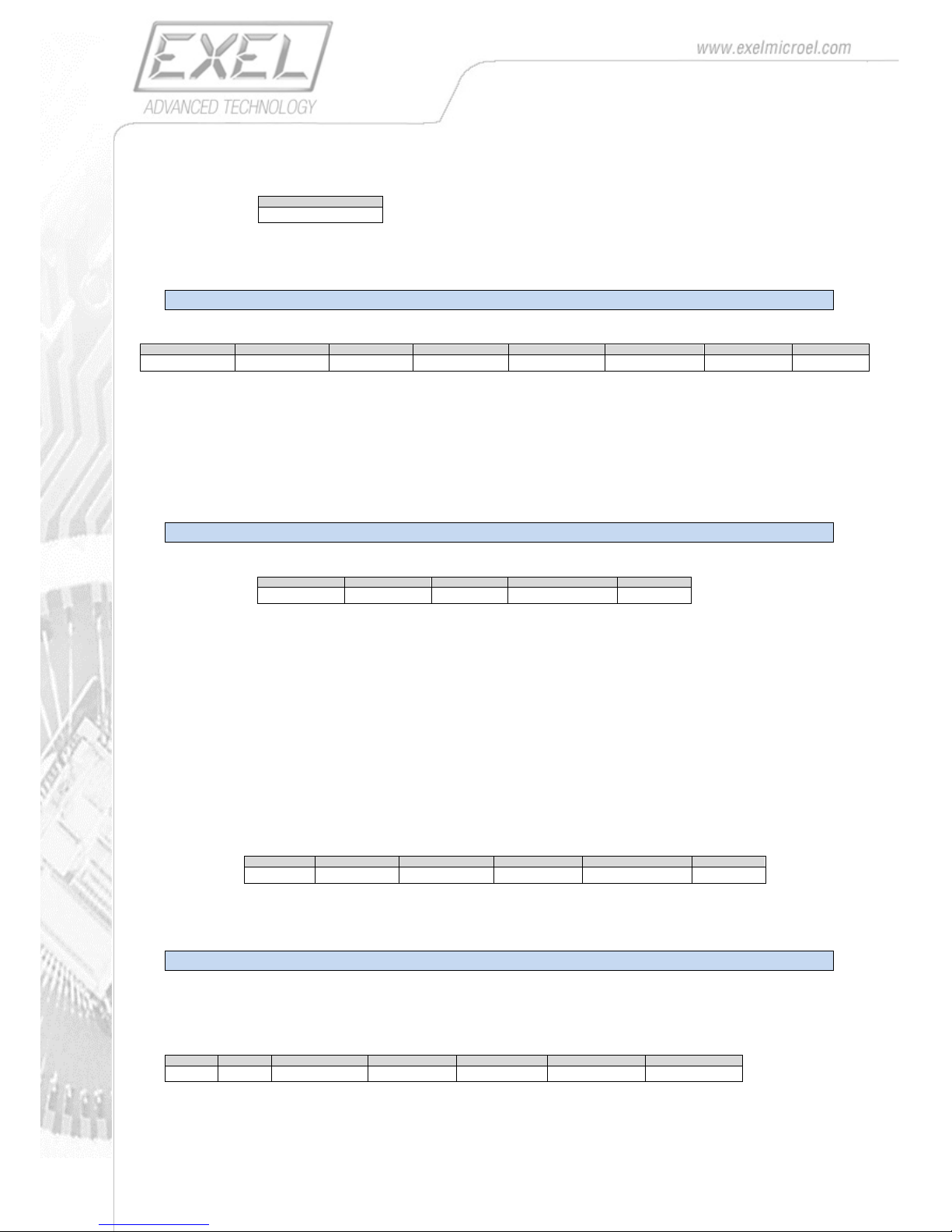
CHKSUM: sum modulo-256 of all previous bytes:
Byte32
CHKSUM
AGMB_Type (Accelerometer, Gyroscope, Magnetometer, vBattery)
Byte0
Byte1
Byte2..Byte3
Byte4 .. Byte9
Byte10 .. Byte15
Byte16 .. Byte21
Byte22 .. Byte23
Byte24
0x20
PKT_TYPE
PKT_CNT
ACC_DATA
GYR_DATA
MAG_DATA
V_BATT
CHKSUM
PKT_HEAD = 0x97 : packet header which identify the type of packet
Remaining data fields are coded the same of AGMOB packet
O_Type (Orientation)
Byte0
Byte1
Byte2..Byte3
Byte4 .. Byte11
Byte12
0x20
PKT_TYPE
PKT_CNT
ORIENT_DATA
CHKSUM
PKT_HEAD = 0x88: packet header which identify the type of packet
Remaining data fields are coded the same of AGMOB packet
IMPORTANT:
Other customizable packet type can be chosen by setting PACKET_TYPE register properly (see the
configuration register paragraph).
Every bit in the PACKET_TYPE register enable/disable a different measurement.
However, the field sequence in the packet is always derived from the generic AGMOB type by
suppressing the unused field.
For instance, the packet type AO has the following coding:
Byte0
Byte1
Byte2..Byte3
Byte4 .. Byte9
Byte10 .. Byte17
Byte18
0x20
PKT_TYPE
PKT_CNT
ACC_DATA
ORIENT_DATA
CHKSUM
RAW _Type
Raw data are values as read from the MEMS sensing elements, before any preprocessing and
compensation take place. This packet format can be useful for advanced users to operate directly on
native data in order to perform specific calibration algorithms.
Byte 0
Byte 1
Byte2
Byte3 .. Byte8
Byte9 .. Byte14
Byte15 .. Byte20
Byte21
0x20
0x0A
PKT_COUNT
ACC_DATA
GYR_DATA
MAG_DATA
CHECKSUM
PKT_HEAD: packet header which identify the type of packet
Page 16
16
Byte0
Byte1
0x20
0x0A
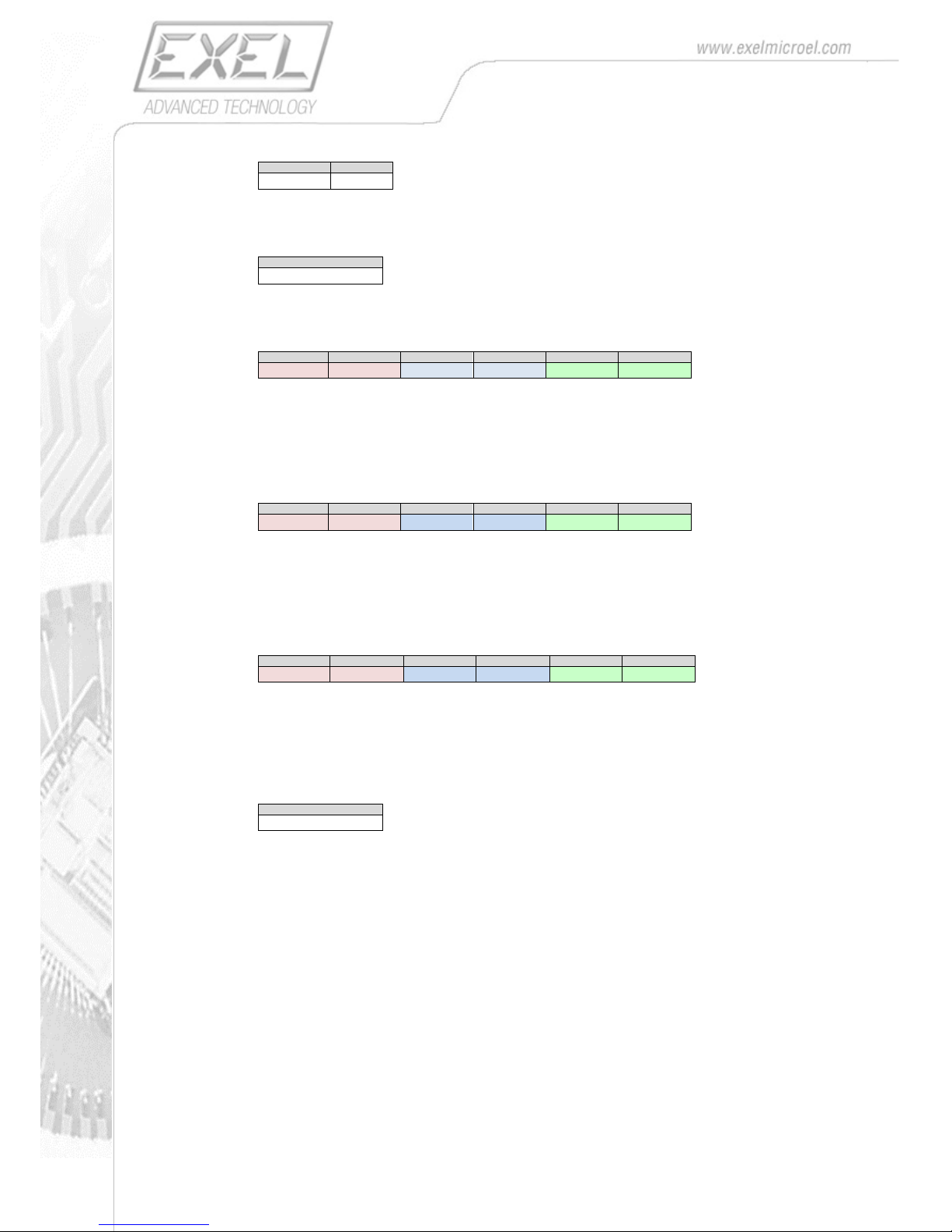
PKT_COUNT: progressive packet number ranging from 0 to 255
Byte2
PKT_CNT
ACC_DATA : acceleration data sub-packed as following:
Byte3
Byte4
Byte5
Byte6
Byte7
Byte8
AccX_L
AccX_H
AccY_L
AccY_H
AccZ_L
AccZ_H
AccX_H : AccX_L : X component of the acceleration (16-bit, 2-complement)
AccY_H : AccY_L : Y component of the acceleration (16-bit, 2-complement)
AccZ_H : AccZ_L : Z component of the acceleration (16-bit, 2-complement)
GYR_DATA: angular velocity data packed as following:
Byte9
Byte10
Byte11
Byte12
Byte13
Byte14
GyrX_L
GyrX_H
GyrY_L
GyrY_H
GyrZ_L
GyrZ_H
GyrX_H : GyrX_L : X component of the angular rate (16-bit, 2-complement)
GyrY_H : GyrY_L : Y component of the angular rate (16-bit, 2-complement)
GyrZ_H : GyrZ_L : Z component of the angular rate (16-bit, 2-complement)
MAG_DATA: magnetic field data packed as following:
Byte15
Byte16
Byte17
Byte18
Byte19
Byte20
MagX_L
MagX_H
MagY_L
MagY_H
MagZ_L
MagZ_H
MagX_H : MagX_L : X component of the magnetic field (16-bit, 2-complement)
MagY_H : MagY_L : Y component of the magnetic field (16-bit, 2-complement)
MagZ_H : MagZ_L : Z component of the magnetic field (16-bit, 2-complement)
CHKSUM: sum modulo-256 of all previous bytes:
Byte21
CHKSUM
8.3. Configuration Commands
The EXLs3’s configuration parameters (sampling frequency, full-scale ranges, etc. ) are mapped into a
register file, where each parameter has a specific address.
The user can modify each parameter in order to adapt the operation of the EXLs3 to the specific
requirement of the user’s application.
The access to the register file is performed by READ_PARAMETER and WRITE_PARAMETER commands
described further.
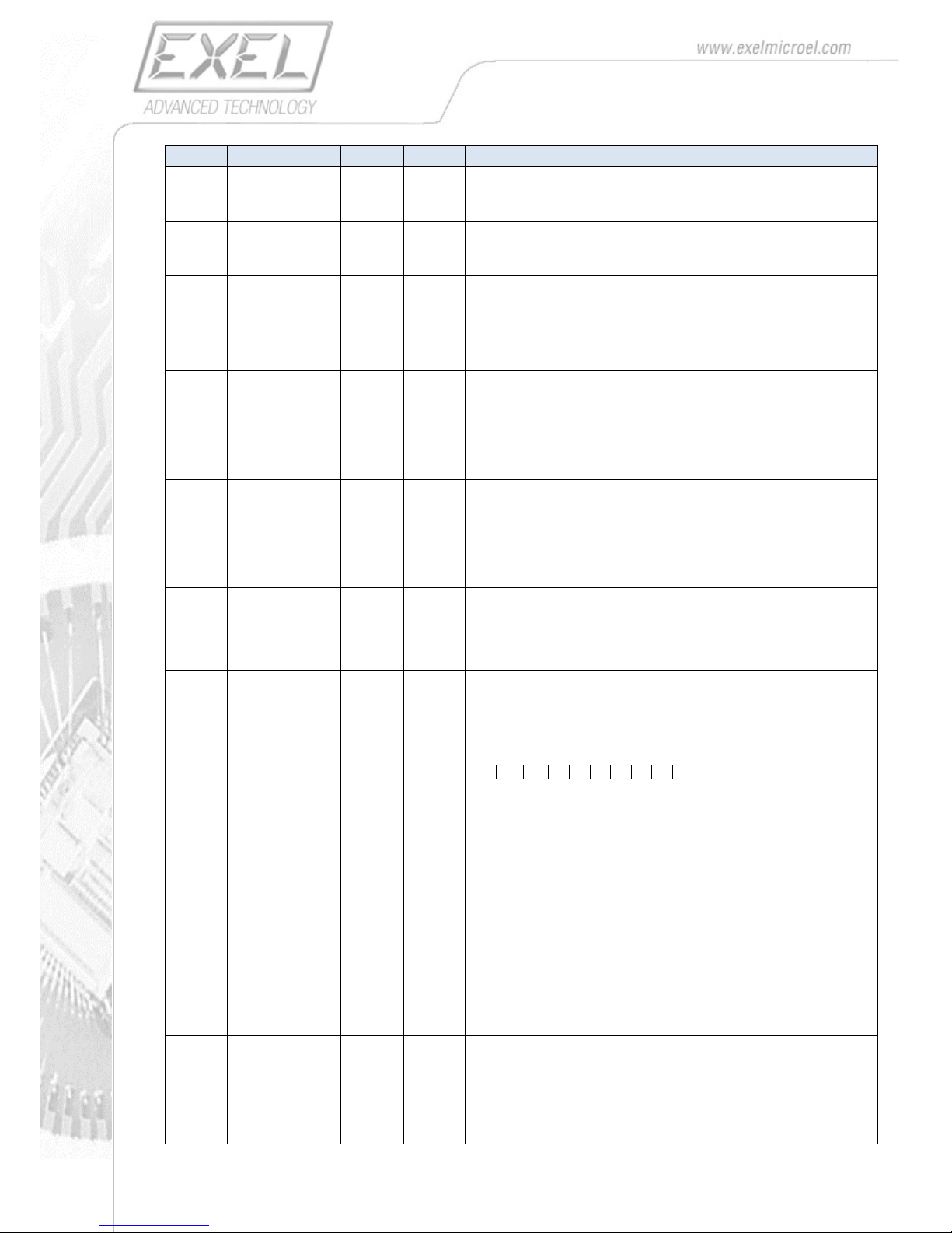
8.4. Configuration Registers
Page 17
17
ADDRESS
PARAMETER NAME
LENGTH
(bytes)
TYPE
DESCRIPTION
0x02
SW_RELEASE
16
String
info about the device’s SW
(read only)
0x12
HW_RELEASE
16
String
info about the device’s HW
(read only)
0x22
BT_NAME
16
string
Bluetooth name
maximum 15 characters max plus null char (‘/0’)
(WARNING: changing this parameter will require entering the Bootloader
Mode in order to take effect)
0x34
ACC_FS
1
u8
Full-scale range of the Accelerometer
0x00 = ±2 g
0x01 = ±4 g
0x02 = ±8 g
0x03 = ±16 g
0x35
GYRO_FS
1
u8
Full-scale range of the Gyroscope
0x00 = ±250 dps
0x01 = ±500 dps
0x02 = ±1000 dps
0x03 = ±2000 dps
0x36
IMU_DLPF
1
u8 Internal sensor low-pass filter (reserved)
0x37
IMU_SRD
1
u8 Internal sensor divider (reserved)
0x38
PACKET_TYPE
1
u8
Output Packet type.
By setting the value of this register it is possible to indicate the information
transported by the data packet when streaming or logging.
The following coding is used:
1 0 0 B O M G
A
where each bit indicates if a specific measurement is enabled
B = Battery voltage
O = Orientation
M= Magnetometer
G = Gyroscope
A = Accelerometer
For example if packet_type = 0x9F (hexadecimal) all the measurements are
output (AGMOB type packet).
0x9F = AGMOB
0x97 = AGMB
0x81 = A
0x91 = AB
0x8F = AGMO
….
0x00 = RAW packet type
0x4E
ORIENT_ALG
1
u8
Selects the algorithm to compute the orientation
0x00 = eCompass (only the accelerometer and the compass are used)
0x01 = Gyro (only the Gyroscope Integration is used )
0x02 = Kalman Filtering (data fusion between Accelerometer, Compass and
Gyroscope is used)
Page 18
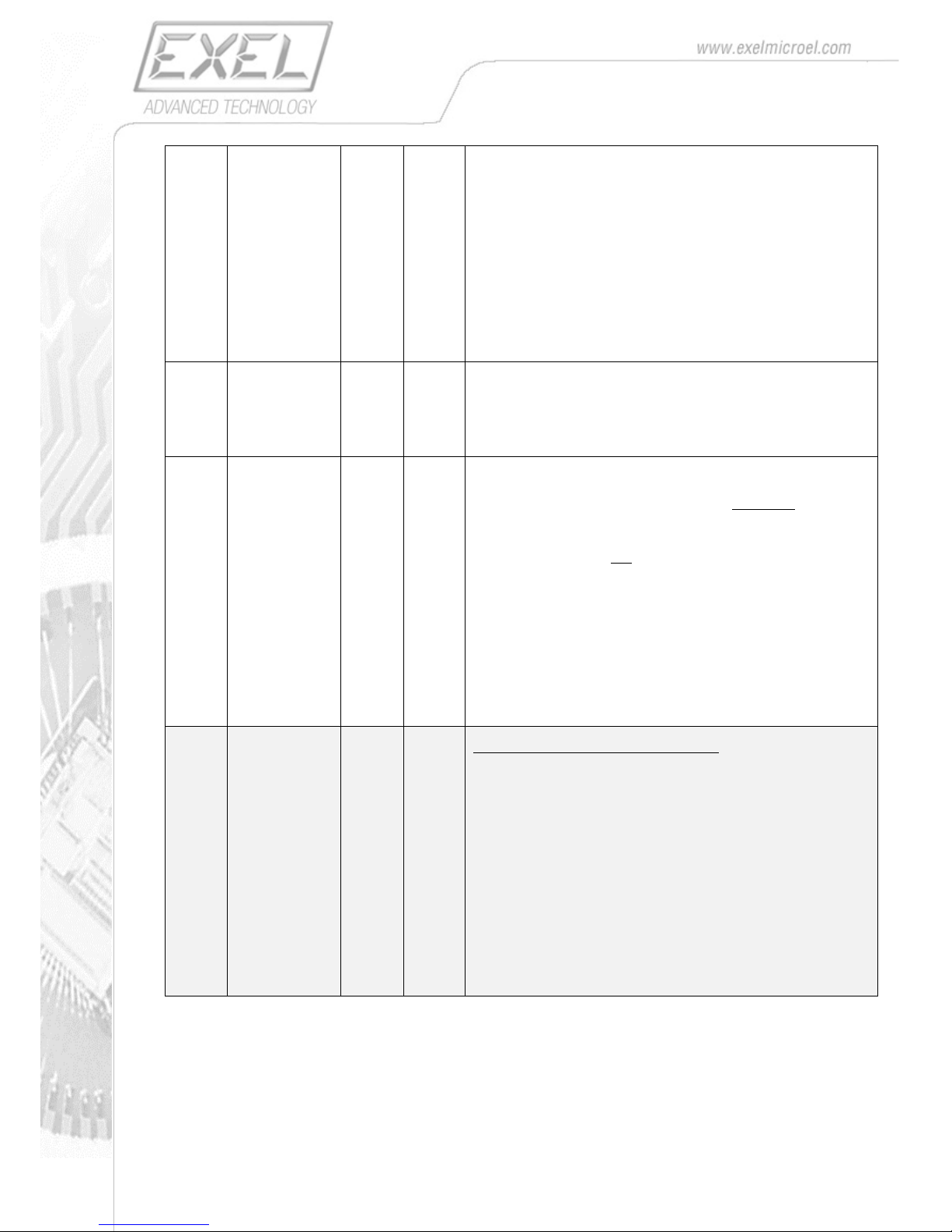
18
0x50
SAMPLE_RATE
1
u8
Selects the frequency of packets (samples) sent to the host
0x00 = 200 Hz (100 Hz if a packet with orientation is chosen)
0x01 = 100 Hz
0x02 = 50 Hz
0x03 = 33.33 Hz
0x04 = 25 Hz
0x05 = 20 Hz
0x06 = 16.67 Hz
0x07 = 12.5 Hz
0x08 = 10 Hz
0x09 = 5 Hz
0x0A = 300 Hz (No magnetometer data, 100 Hz if a packet with orientation
is chosen)
0x51
STREAM_LOG
1
U8
Select the Stream and or Log Mode when START command is issued
0x00 = Stream packets via bluetooth
0x01 = Log packets on file in the EXLs3’s internal flash disk
0x02 = Stream & Log packets
0x52
SWRFD
1
U8
Start When Removed From Dock mode
0x00 = data streaming and/or logging begins immediately after START
command has been sent
0x01 = data streaming and/or logging begins immediately after START
command has been sent only if the EXLs3 is not powered by the docking
station, otherwise it waits the dock’s power supply being removed before
starting streaming/logging.
When the EXLs3 is put back in the docking station and the power supply is
restored, it stops streaming/logging
This behavior can be used to synchronize the start/stop time of several
sensors.
0x02 = continuous data logging when the EXLs3 is not powered by the
docking station, without start/stop commands. In this operating mode no
Bluetooth connection is required.
0x53
WAKEUP_MODE
1
U8
*Only available on EXLs3 with vibration sensor.
It configure the device’s wake-up mode
0x10 = BUTTON: the device switches-on by pressing the button
0x20= VIBRO_FAST: the device switches-on with vibration (High
sensitivity).
0x21= VIBRO_MED: the device switches-on with vibration (Medium
sensitivity).
0x22= VIBRO_SLOW: the device switches-on with vibration (Low
sensitivity).
0x30= BUTTON + VIBRO_FAST: the device switches-on with vibration
(High sensitivity) or by button.
0x31= BUTTON+VIBRO_MED: the device switches-on with vibration
(Medium sensitivity) or by button.
0x32= BUTTON + VIBRO_SLOW: the device switches-on with vibration
(Low sensitivity) or by button.
Page 19
19
8.5. Configuration Parameter Access
The access to the register file is performed by a generic READ_PARAMETER and WRITE_PARAMETER
commands, which also allow readings or writings of a sequence of multiple consecutive parameters.
READ_PARAMETERS
Use this command to read one or more parameters from the sensors. Parameters are mapped in a
buffer as described in the related paragraph. The command lets the user read N bytes starting from
Add_H:Add_L
Byte0
Byte1
Byte2
Byte3
Byte4
0x65
N
Add_L
Add_H
CHKSUM
The sensor responds with a packet containing the N bytes required of the parameter buffer
Byte0
Byte1 Byte(N-1)
ByteN
Data0
Data1
…
Data(N-1)
CHKSUM
This command is only accepted if the sensor is not in streaming mode
WRITE_PARAMETERS
Use this command to write one or more parameters to the sensor.
Byte0
Byte1
Byte2
Byte3
Byte4 .. Byte(4+N-1)
Byte(4+N)
0x64
N
Add_L
Add_H
Buffer_data …
CHKSUM
The sensor responds with an acknowledge:
Byte0
0x01
This command is only accepted if the sensor is not in sampling/streaming mode. The parameters change
takes effect from the following sampling/streaming command. New parameters are stored in volatile
memory so they are lost when the device is switched-off. To save permanently the current parameters
use SAVE_PARAMETERS command.
SAVE_PARAMETERS
Use this command to save in non-volatile memory the current set of parameters, so that it will be
retained also after switching the EXLs3 off.
Byte0
Byte1
0x66
0x66
The sensor responds with an acknowledge
Byte0
0x01
This command is only accepted if the sensor is not in streaming mode
Page 20
20
EXAMPLES OF CONFIGURATION COMMANDS:
Set SAMPLE_RATE at 100 Hz
WriteParameter command 1 byte, at address 0x50, value = 0x01
OpCode
Nbyte
AddL
AddH
Value
CHKSUM
0x64
0x01
0x50
0x00
0x01
0xB6
Set SAMPLE_RATE at 200 Hz
WriteParameter command 1 byte, at address 0x50, value = 0x00
OpCode
Nbyte
AddL
AddH
Value
CHKSUM
0x64
0x01
0x50
0x00
0x00
0xB5
Set PACKET_TYPE at ORIENT_Type
WriteParameter command 1 byte, at address 0x38, value = 0x02
OpCode
Nbyte
AddL
AddH
Value
CHKSUM
0x64
0x01
0x38
0x00
0x02
0x9F
Set ACC_FS at ±16 g
WriteParameter command 1 byte, at address 0x34, value = 0x03
OpCode
Nbyte
AddL
AddH
Value
CHKSUM
0x64
0x01
0x34
0x00
0x03
0x9C
Read SW_RELEASE
ReadParameter command 16 byte, at address 0x02
OpCode
Nbyte
AddL
AddH
CHKSUM
0x65
0x0F
0x02
0x00
0x76
The EXLs3 responds with a stream similar to this:
Byte0
Byte1
Byte2
Byte3
Byte4
Byte5
Byte6
Byte7
Byte8
Byte9
Byte10
Byte11
Byte12
Byte13
Byte14
Byte15
Byte16
‘S’
‘W’
‘=‘
‘6’
‘.’
‘0’
‘9’
‘ ’
‘ ’
‘ ’
‘ ’
‘ ’
‘ ’
‘ ’
‘ ’
0x00
Checksum
Page 21
21
8.6. Real Time Clock configuration
The EXLs3 device is equipped with a Real Time Clock which allow time keeping for proper file creation
and time stamping.
It is possible to read/write the RTC register by using the following commands.
SET_CLOCK
Use this command to set the time and date value in the RTC.
Byte0
Byte1
Byte2
Byte3
Byte4
Byte5
Byte6
Byte7
0x6E
YY
MM
DD
HH
mm
SS
CHKSUM
YY = Year [0..99] MM = Month [1..12] DD = Day [1..31]
HH = Hour [0..23] Mm = Minute [0..59] SS = second [0.59]
The sensor responds with an acknowledge:
Byte0
0x01
This command is only accepted if the sensor is not in sampling/streaming mode.
GET_CLOCK
Use this command to GET the data and time from RTC:
Byte0
Byte1
0x6F
0x6F
The sensor responds with:
Byte0
Byte1
Byte2
Byte3
Byte4
Byte5
Byte6
YY
MM
DD
HH
mm
SS
CHKSUM
YY = Year [0..99] MM = Month [1..12] DD = Day [1..31]
HH = Hour [0..23] Mm = Minute [0..59] SS = second [0.59]
This command is only accepted if the sensor is not in sampling/streaming mode.
Page 22
22
8.7. Other commands
POWER_OFF
Use this command to switch-off the device.
Byte0
Byte1
Byte2
Byte3
Byte4
0x32
0x32
0x32
0x32
CHKSUM
The sensor responds with an acknowledge, right before switching-off.
Byte0
0x01
This command is only accepted if the sensor is not in sampling/streaming mode.
RESTORE_PARAMETERS
Use this command to restore all settings to the default values.
Byte0
Byte1
0x67
0x67
The sensor responds with an acknowledge.
Byte0
0x01
This command is only accepted if the sensor is not in sampling/streaming mode.
NOTE: This command does not reset the calibration parameters
START_BOOTLOADER
Use this command to start the bootloader at the next device’s switching-on.
Byte0
Byte1
Byte2
Byte4
0x80
0xBA
0xBA
CHKSUM
The device responds with an acknowledge..
Byte0
0x01
This command is only accepted if the sensor is not in sampling/streaming mode.
NOTE: This command is only supported by devices with bootloader v.1.05 and above.
Page 23
23
Appendix A. Firmware Update
The EXLs3 unit is equipped with a bootloader, which employs the Bluetooth connection to upload a new
firmware on the device.
The firmware must be provided as a binary file (.bin) and should be transmitted to the device via a serial
terminal emulator which support Y-modem data transfer (e.g TeraTerm or HyperTerminal).
The bootloader mode can be entered when turning on the device be holding pressed the switch-on
button for 5 seconds, until the red led starts blinking.
At this point the device is in the bootloader mode and will stay here until it receives further instructions. A
button press will exit the bootloader mode and normally initialize the device.
When in the bootloader mode, the device waits the connection from the terminal emulator.
The following instructions apply to Teraterm terminal emulator, but can be used with any similar program.
We are also assuming that the user already paired the device with the PC, thus having a COM port
corresponding to the device.
WARNING! This operation should be done with care and at your own risk.
Be sure that the binary file you are going to load to the EXLs3 unit is provided by EXEL only.
If the firmware file is not correct your device can be damaged permanently.
Be sure that the battery is fully charged before starting the updating procedure, as a the interruption of the
process, for any reason, can damage your EXLs3 unit.
To upload a new firmware the user must:
1. Put the device in BOOTLOADER mode (red LED blinking)
2. Start Teraterm on the host PC
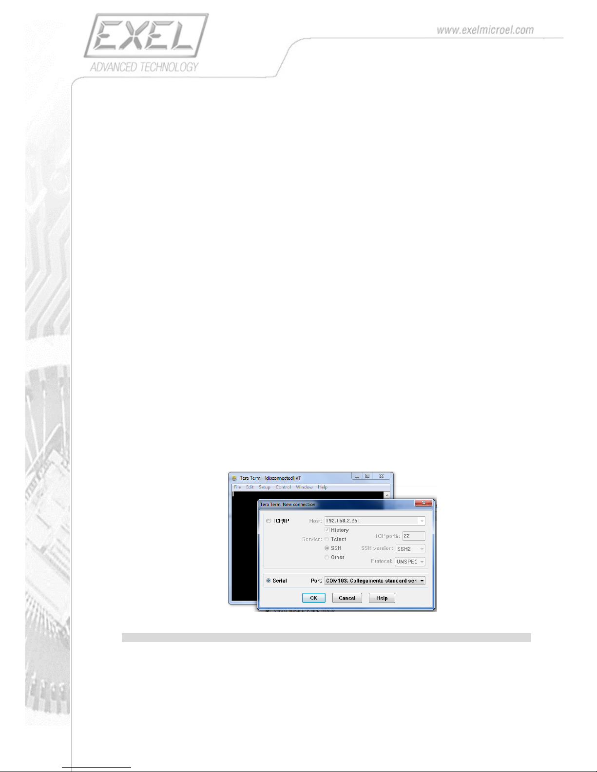
3. Connect to the EXLs3 unit by selecting in the File / New connection menu the COM port
associated with the EXLs3 unit
Note: The following points 4. and 5. are not required from the bootloader version >1.04
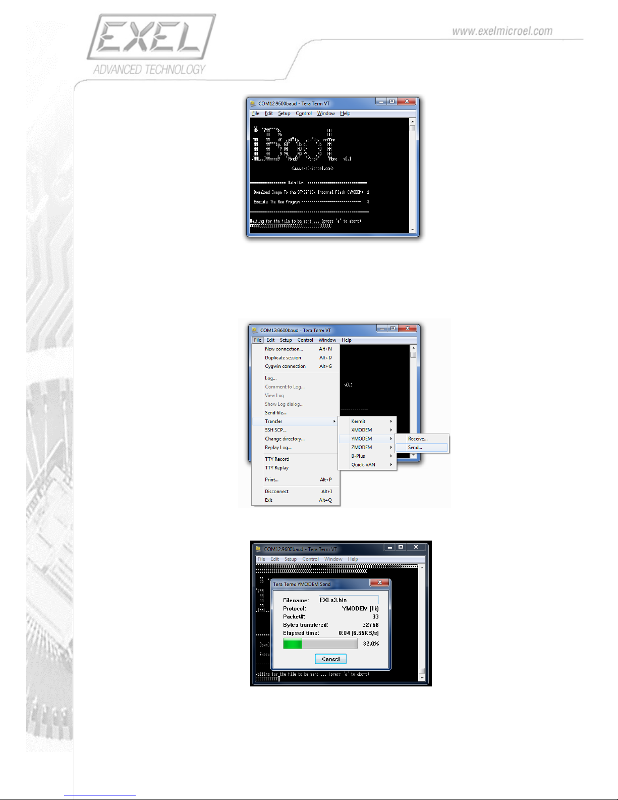
4. Once the communication channel is open press on the PC’s keyboard the keys SHIFT + A, the
following bootloader splash screen is shown:
Page 24
24
5. Press on the keyboard the key “1”.
The bootloader starts showing a continuous sequence of “C” and wait the file to be uploaded.
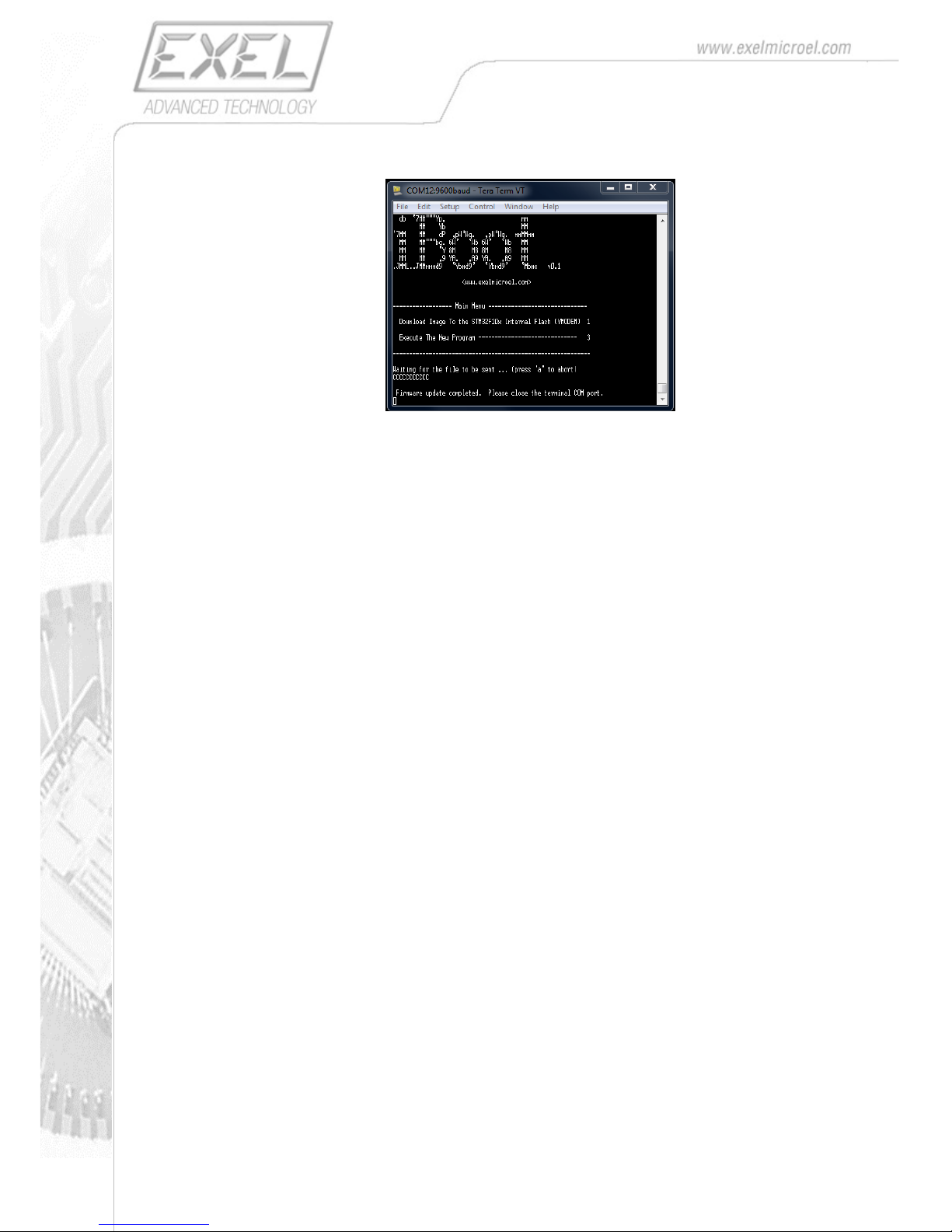
6. Select the file to send (EXLs3_xxxx.bin) to the EXLs3 unit by choosing File / Transfer /
Ymodem / Send option.
WARNING: only select trusted binary files provided by EXEL, otherwise you can damage your
product permanently.
7. The file transfer take place
Page 25
25
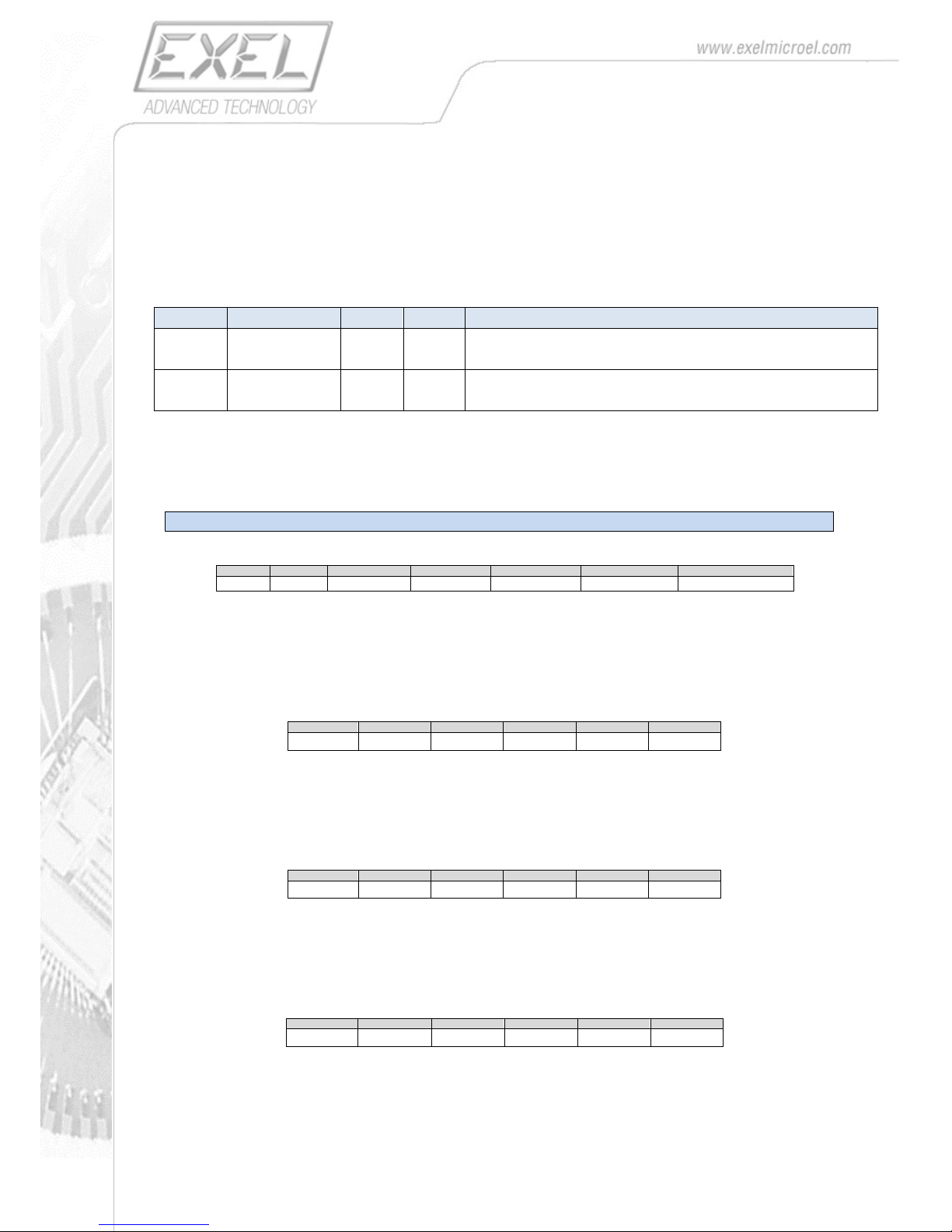
8. When the process is completed you can close the communication port by pressing File /
Disconnect
9. After the firmware transfer the EXLs3 unit should exit bootloader mode and the LED should turn
green.
10. It is advised you switch-off and then switch-on the EXLs3 unit before using it.
Page 26
26
LEGACY FUNCTIONS
The following configuration parameters and packet format have been kept for compatibility with the initial
implementation.
It is advised not to use them anymore, and use newer packet formats
CONFIGURATION PARAMETERS
ADDRESS
PARAMETER NAME
LENGTH
(bytes)
TYPE
DESCRIPTION
0x38
PACKET_TYPE
1
u8
0x01 = CALIB_Type (Calibrated data)
0x02 = ORIENT_Type (Quaternions)
0x4F
SEND_BATT
1
u8
0:
1: Battery Voltage is sent periodically with a dedicated packet
PACKETS FORMAT
CALIB_Type (Accelerometer, Gyroscope, Magnetometer)
Byte 0
Byte 1
Byte2
Byte3 .. Byte8
Byte9 .. Byte14
Byte15 .. Byte20
Byte21
0x20
PKT_ID
Pkt_count
ACC_DATA
GYR_DATA
MAG_DATA
CHECKSUM_XOR
Packet Header: the first packet byte is always 0x20
PKT_ID: the identifier for the packet type. For the calibrated data packet it’s 0x0B
PKT_COUNT: progressive packet number ranging from 0 to 255
CHECKSUM_XOR: calculated as XOR of previous Bytes
ACC_DATA : acceleration data sub-packed as following:
Byte3
Byte4
Byte5
Byte6
Byte7
Byte8
AccX_L
AccX_H
AccY_L
AccY_H
AccZ_L
AccZ_H
AccX_H : AccX_L : X component of the acceleration (2-complement)
AccY_H : AccY_L : Y component of the acceleration (2-complement)
AccZ_H : AccZ_L : Z component of the acceleration (2-complement)
GYR_DATA: angular rate data packed as following:
Byte9
Byte10
Byte11
Byte12
Byte13
Byte14
GyrX_L
GyrX_H
GyrY_L
GyrY_H
GyrZ_L
GyrZ_H
GyrX_H : GyrX_L : X component of the angular rate (2-complement)
GyrY_H : GyrY_L : Y component of the angular rate (2-complement)
GyrZ_H : GyrZ_L : Z component of the angular rate (2-complement)
MAG_DATA: magnetic field data packed as following:
Byte15
Byte16
Byte17
Byte18
Byte19
Byte20
MagX_L
MagX_H
MagY_L
MagY_H
MagZ_L
MagZ_H
MagX_H : MagX_L : X component of the magnetic field (2-complement)
MagY_H : MagY_L : Y component of the magnetic field (2-complement)
MagZ_H : MagZ_L : Z component of the magnetic field (2-complement)
Page 27
27
ORIENT_Type (quaternion)
When this packet type is chosen, the node samples the sensors, applies the internally stored calibration
and computes the orientation of the device using one of the available algorithms. The orientation is
represented in quaternion form and represents the orientation of the device with respect to a local earth
fixed frame. The node’s body reference frame is the one illustrated in Figure 1, and the earth default
reference frame has x pointing north, y pointing west and z pointing upwards (NWU – North-West-Up).
An alternative reference frame can be chosen (NED – North-Est-Down).
Byte 0
Byte 1
Byte2
Byte3 .. Byte6
Byte7 .. Byte10
Byte11 .. Byte14
Byte15 .. Byte18
Byte19
0x20
PKT_ID
Pkt_count
q0
q1
q2
q3
CHECKSUM_XOR
Packet Header: the first packet byte is always 0x20
PKT_ID: the identifier for the packet type. For the orientation data packet it’s 0x0C
PKT_COUNT: progressive packet number ranging from 0 to 255
q0 – q3: the orientation of the device expressed in quaternion form. Each one of the components
is a 32-bit floating point number in the IEEE 754 standard. The four bytes are organized as
follows:
Byte3
Byte4
Byte5
Byte6
Byte 0
Byte 1
Byte 2
Byte 3
IMPORTANT: The CHECKSUM is calculated as XOR of previous Bytes
VBATT (Battery Voltage)
This packet reports the battery voltage in mV.
It is sent periodically (typically every 5 seconds) if SEND_BATTERY (address 0x4F) is set to 1.
Byte 0
Byte 1
Byte2
Byte3
Byte4 .. Byte14
Byte15
0x20
0xBA
Vbatt_L
Vbatt_H
0
CHECKSUM_XOR
IMPORTANT: The CHECKSUM is calculated as XOR of previous Bytes
 Loading...