

Page 1
Installation Manual
< Multi- Plate Clutch >
Product number
GT01SD
ET01SD
ET02SD
ET03SD
Thank you for purchasing an Exedy Racing Clutch.
Please read through this installation manual before use.
Please keep this manual during the life of the product.
Vehicle application
Make Type Engine type
CHEVY
PONTIAC
FORD
CORVETTE
1997 – 2004
GTO
2004-On
MUSTANG
1996 - 2004
5.7L
(LS1 / LS6)
4.6L
(SOHC/DOHC)
for further information
please make contact with
DAIKIN CLUTCH CORPORATION
8601 Haggerty Rd. S.
Belleville, MI, 48111
Phone: (800) 346 – 6091
Fax: (734) 397 – 7300
www.Daikin-Clutch.com
REF NO.:M190
DATE:2003/ 10/ 3
-1-
Page 2
Installation manual introduction
This installation manual includes useful information to prevent
problems from occurring during installation.
1. Please read through this manual before installation.
2. Installation work has to be done by a professional installer who
will use the product safely.
3. Please do not use the product wrongfully nor modify the parts.
In such case, we will not take any responsibility.
4. We will not accept any claim nor return as this product
is used predominately for racing and specification may
change without prior notice.
5. Please keep this manual following installation.
For safety
Please note the following as these are important warnings and cautions for
our customers.
Warning
Ignoring this warning may cause death or extreme injury.
!
Caution
Ignoring this caution may cause injury or damage.
!
M
190
-2-
Page 3

Caution during handling
1.
!
2.
Do not place the product on the floor directly
as this may cause rust to appear on the product.
!
3.
Do not throw or drop the product as it is a
precision part.
!
Caution during installation
Caution
Caution
Caution
As this product is heavy handle carefully when
removing it from the box.
1. Warning
Use a licensed installer as the transmission
unit is to be taken out of the vehicle.
!
2.
manual of the vehicle and this installation manual.
!
3. Warning
Do not apply this product to vehicles other than
!
those specified by EXEDY.
4.
Do not modify this product unless instructed
to in this manual.
!
5.
Warning
Warning
Warning
Install the product according to the maintenance
If a failure such as abnormal noise, vibration, odor or
!
M190
disengagement problem occurs during driving, stop the
vehicle immediately and have a licensed garage inspect
the vehicle.
-3-
Page 4
!
Installation procedure
1. Loosen the clutch cover to flywheel bolt and disassemble the kit.
(See attached photo #A1)
Caution
Do not loosen the bolt which fastens the intermediate plate
To the adapter ring. If this bolt is loosened by accident,
tighten once again using Locktight No272 to
!
2. Use the specified bolt (Flywheel installation bolt)
13.3 - 19.8 Lb-ft (17.7 - 26.5 Nm). (See attached photo #A2)
and fix the flywheel to the crankshaft according to the maintenance manual
issued by the vehicle manufacturer.
Tighten the crank bolt diagonally with equal force applying torque as
specified by the vehicle manufacturer.
Product Number Vehicle Specified torque
GT01SD CORVETTE 74 Lb-ft (99 Nm)
ET01SD
ET02SD
ET03SD
3. Assembly
<Order of assembly> Twin plate
Flywheel -> Flywheel Disc -> Intermediate Plate / Pressure Plate Side
Disc-> Clutch cover Assy.
Order of assembly
The clutch cover, intermediate plate set and flywheel should be assembled
in a manner which allows the painted balance mark to be aligned.
If the marking is not met, it will cause unbalance, noise and
vibration problems.
Caution
MUSTANG 59 Lb-ft (79 Nm)
Be careful of the direction/location of the discs.
!
M190
Caution
Discs should be facing the same direction.
-4-
Page 5
!
Apply grease specified by the vehicle manufacturer to the spline
!
4. Set up the center bar to the pilot at engine side, center each
disc and align the teeth. Tighten the clutch cover bolt.
The genuine main drive shaft is recommended for this process.
If the clutch plate centers are not aligned, it will be
Caution
hub then insert the shaft and wipe away any grease that is forced
out.
Caution
difficult to assemble the T/M and it will cause damage to the
discs.
Specified torque of clutch cover to flywheel bolt:
17.5 - 24.5 LB-ft (23 - 33Nm)
*Unequal bolt tightening will cause disengagement problems
and judder/shudder.
5. Confirm that lever height is equal after tightening. If it
is not equal, then restart from procedure 3.
6. Replace the T/M.
Purchase a new release bearing and apply grease
to sliding surface.
Follow the maintenance manual issued by the vehicle manufacturer.
Caution
Do not hit the spline teeth with the edge of the main drive
shaft. It will cause disengagement problems or damage to the
!
7. Stroking adjustment
clutch disc.
After installing of this kit, the pedal position (engagement or
disengagement point) may change.
Adjust the pedal according to the maintenance manual issued
by the vehicle manufacturer.
M190
-5-
Page 6

Caution during operation
1.
!
2.
!
3. In the early stage, it is not abnormal if subtle noise
and chattering occurs. This is due to the characteristics of metal facings.
4.
!
Caution
After installation, drive carefully and gently for approx.
400 miles (640 km)
friction surface is not contacting fully with the mating surface; It will
cause burning, judder/shudder or short life.
Caution
It is recommended to re-adjust the pedal stroke after
the break in period. Due to the nature of metal facing
material, half engaged clutch operation will also be affected
after break in period but this is a normal symptom.
Warning
Do not change any release control function of the vehicle.
(The clutch is used under normal condition.)
. If the clutch is used in a condition where the
5.
!
6.
!
<Advice>
Record the new release fork position and confirm its variation.
Facing wear amount can then be foreseeable. Preventative maintenance
before the discs are worn out is a key factor to maintain steady
performance.
Maximum facing wear: Facing thickness 0.106 inch (2.7 mm)
(at new 0.142 inch (3.6 mm))
Warning
Caution
This clutch system is specially designed for racing purposes,
therefore pedal effort is slightly heavier and start operation
difficult than standard manual clutch products. Avoid using if
you are not completely confident with your driving technique
and physical strength.
The life of a metal clutch may be adversely affected by
driving technique and driving conditions.
is more
M190
-6-
Page 7

7.
!
Warning
8.
Warning
!
Caution: If the clutch is used in the half engaged position for
extended periods of time,
the clutch set will generate high temperatures. This high heat
creates expansion or deformation which causes
disengagement problems temporarily or permanently. If this
occurs stop driving and allow the clutch to cool down. For
maximum friction surface temperatures see over.
Do not machine any part of this product, otherwise the
strength of each part will be reduced and may fail
prematurely.
9.
Warning
The bolts have to be tightened at the specified torque.
!
The mating surfaces should be cleaned, wiped with a clean
towel to remove any foreign waste they may affect the
10.
performance of the clutch.
Warning
The bolts are the very important parts. Use either genuine
!
parts or the bolts included as auxiliary parts in the box.
Do not reuse the old bolts after un-tightening.
M190
-7-
Page 8
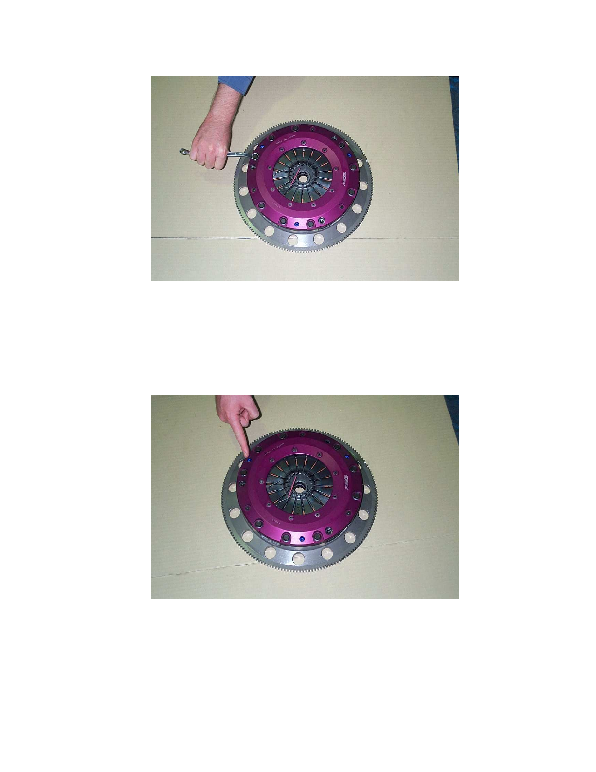
(Ref #A1) (PRESSURE PLATE COVER TO FLYWHEEL BOLTS)
(Ref #A2) (NEVER LOOSEN THE INDICTED CAP SCREW)
M190
-8-
 Loading...