

Page 1
要保管
Keep this manual
取扱説明書
Installation manual
この度は、EXEDY RACING CLUTCH をご購入いただきまして誠にありがとうございま
す。
ご使用前に必ずこの取扱説明書をよくお読み下さい。
Thank you very much for your purchase of EXEDY RACING CLUTCH.
Be sure to read this installation manual prior to use.
発行日:2005/03/18
Issued on: March 18, 2005
発行元:(株)エクセディ SBC
Issued by: EXEDY Corporation Sports BC
M330 - 1 -
Page 2

!
!
注意
CAUTION
注意
CAUTION
セミカーボンは耐磨耗性が非常に良い為、当たりがつきにくくまた相手面に皮膜
が形成されないと十分に性能を発揮することができませんので、慣らし及び焼入
れを必要とします。
Break in and quenching are required for this product, since semi carbon, featu ring
highly excellent wear resistance, is hard to be provided with a good contact, an d
its performance cannot be fully utilized unless the surface of the co unt erpart is
coated with a film.
☆ 慣らし及び焼入れ方法
Break in procedure
①
② ①の慣らし終了後、
取付け直後など摩擦面当たりが十分でない状態で全開走行を行うとすべりが発生
する可能性があります。
Immediately after installing the clutch, the contact friction fa ce is not efficient. If
you accelerate with full throttle before break in, slippage may occur.
セミカーボンは街乗り走行など低温時には摩擦係数が低く、スポーツ走行時は摩
擦係数が高くなる特徴を持っています。
街乗り走行からの急加速やサーキットでの1周目などではすべりを発生すること
があります。スポーツ走行を行う前にはクラッチを暖めてから使用ください。
The friction coefficient of s em i c arb on is low at low temperatures, such as normal
city driving - however, the coefficient is ve ry hig h at hi gh tem p erat ures , such as
drag or road racing. Thus, if driving style is su dde nly increased during city driving,
or on the first lap of a road course, slippag e m ay oc cur. Warm up the clutch before
a sports driving!
PROPER WARM UP PROCEDURE FOR CARBON CLUTCH SPORT DRIVING
Exedy recommends three, five-second “slips” of the clutch, within 30 seconds to
obtain maximum torque holding capacity. This should be done before hard driving
to ensure slippage does not occur.
2000r/min
安
(慣らしは発進時に行われます。シフトアップ時や高速道路の走行では慣
らしが進みません)
Normal city driving for minimum 300 km, ap prox im a te ly 500 times “normal”
2000 rpm take offs is the goal. Break in is only sufficient under city driving
with frequent engagement/disengagement of the clutch - “highway” drive do
not count 1:1 for break-in distance.
その際は安全で広い場所で行ってください。
After the break in described above in “Step 1” is com pl et e, perform several
(4-5) aggressive launches of the car at approxim ate ly 5000 rpm . Pe rform
this step in a safe and controlled environment, such as a race track or drag
strip.
程度の発進操作で発進頻度の高い市街地を
500
回の発進)
5000r/min
程度で数回発進してください。
300km
程度走行(目
M330 - 2 -
Page 3
取り扱い説明書について
本製品を正しくお使い頂き、あなたや他の人々への危害や財産への損害を未然に防止する為の注意事項
を記載しています。
This installation manual incl udes useful information to prevent problem s fr om oc curring during
installation.
1.
本書は取付けを行う前に必ず読み、良く理解したうえで作業を行って下さい。
Please read through this manual before insta llation.
2.
取付けは必ず専門業者に依頼し、取付け後は本書に記載されている内容を守り安全に使用して下さ
い。
Installation work has to be done by a professio na l in s taller who will use the product safely.
3.
お客様及び第三者が、本製品及び付属品を誤使用、又は改造したことにより受けた損害については、
当社は一切の責任を負いかねます。
Please do not use the product wrongfully nor modify the parts. In such case, we will not take any
responsibility.
4.
本製品は競技用部品の為、クレーム返品には応じかねます。また改良の為予告なく仕様を変更する
事があります。
We will not accept any claim nor return as th is prod uc t is used predominately for racing and
specification may change without prio r noti c e.
5.
取付け後も本書は大切に保管下さい。
Please keep this manual followin g ins tallation.
安全上の注意
For safety
!
!
本書では下記の様な表示にて、お客様への注意レベルを示しています。
Please note the following as the se are important warnings and cautions for our customers.
警告
WARNING
注意
CAUTION
Installation manual introduction
この表示を無視して誤った取り扱いをすると、人が死亡又は重傷を負う可能性が
想定される内容を示しています。
Ignoring this warning may cause death or extreme injury.
この表示を無視して誤った取り扱いをすると、人が傷害を負う可能性が想定され
る内容及び、物的損害の発生が想定される内容を示しています。
Ignoring this caution may cause injury or damage.
M330 - 3 -
Page 4
取り扱い上のご注意
1.
2.
3.
4.
5.
!
!
!
!
!
注意
CAUTION
注意
CAUTION
注意
CAUTION
注意
CAUTION
注意
CAUTION
Caution during handling
梱包から取り出す際には、製品が重いので取り扱いに注意して下さい。
As this product is heavy, handle care fully when removing it from the box.
プルタイプの場合、ダイヤフラムの内周部を絶対に持たないで下さい。
(カラーやCリングが変形し
As for the pull type, NEVER hold the inner diam eter of the diaphragm.
(Otherwise, the color or C-ring may be deformed, leading to release of the
bearing.)
直置きはしないで下さい。
(錆発生の原因になります。)
Do not place the product on the floor directly as this may cause rust to appear on
the product.
精密部品ですので運搬時、投げ積みや落下など手荒な取り扱いをしないで下さ
い。
Do not throw or drop the product as it is a precision part.
カーボンは皮膚に付着すると人によっては、かゆみや湿疹を伴うことがあるた
め、保護手袋や保護服などを着用してください。
If you touch carbon, you may have an itch or ec z ema. Wear protective gloves or
clothes.
BRG
取り付け上のご注意 Caution during installation
1.
2.
3.
4.
!
!
!
!
警告
WARNING
警告
WARNING
警告
WARNING
警告
WARNING
クラッチの交換作業は、トランスミッションの脱着作業を伴いますので必ず認証
指定工場で行って下さい。
Use a licensed installer as the transmission unit is to be taken out of th e veh ic le.
交換の際は必ず自動車メーカー発行の当該車種の整備マニュアルに従い、本書の
注意事項を守って作業を行って下さい。
Install the product according to the maintenance manual of the vehicle and this
installation manual.
適応車種以外の車輌への取付けは、絶対に行わないで下さい。
Do not apply this product to vehicles other tha n th os e s pe c ified by EXEDY.
製品の加工、改造、決められた所以外の分解は絶対に行わないで下さい。
Do not modify this product unless ins tructed to in this manual.
抜けの原因になります。)
M330 - 4 -
Page 5
5.
!
警告
WARNING
走行中に不具合(異音・振動・異臭・切れ不良)が発生した時は、直ちに走行を
中止し、専門業者で点検を受けて下さい。
If a failure such as abnormal noise, vi bration, odor or disengagement problem
occurs during driving, stop the vehicle immediately and have a licensed garage
inspect the vehicle.
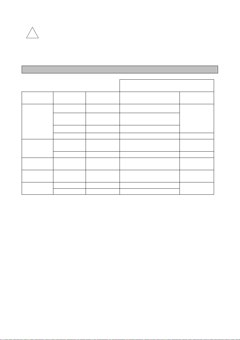
適応車種及び商品品番 Applicable vehicle and model
メーカー
Manufacturer
日産
NISSAN
トヨタ
TOYOTA
マツダ
MAZDA
三菱
MITSUBISHI
スバル
SUBARU
NM032SDMC
NM042SDMC
NM052SDMC
NM072SDMC
TM032SDMC
TM042SDMC
ZM022SDMC
MM022SDMC
FM012SDMC
FM022SDMC
商品品番
Part No.
クラッチサイズ
Clutch size
Vehicle model
225 BNR32
φ
225
φ
225 BNR34
φ
225 Z33 VQ35DE
φ
225
φ
225 JZA80 2JZ-GTE
φ
225 FD3S 13B-REW
φ
225 CN/CP/CT9A 4G63
φ
225 GC8
φ
225 GDB
φ
BNR32 後期、BCNR33
BNR32 later model, BCNR33
JZX90/100/110
適合車種
Applicable vehicle model
車種
JZA70
エンジン型式
Engine model
RB26DETT
1JZ-GTE
EJ20
M330 - 5 -
Page 6
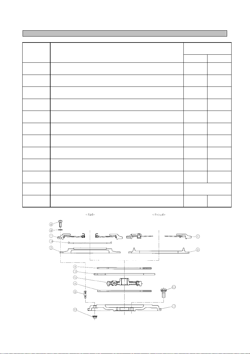
構成部品及び構成図
構成図 NO.
No.
クラッチカバー
①
Clutch cover Assy (CCA)
プレッシャープレート(PP)
②
Pressure plate (PP)
センタープレート(
③
Center plate (IMP)
ドリブンプレート(DP)
④
Driven plate (DP)
センターハブダンパー(
⑤
Center hub damper
ドライブボス(
⑥
Drive boss (D.BOSS)
FLYWHEEL
⑦
Flywheel (F/W)
ボルト
⑧
Bolt
平ワッシャー
⑨
Washer
ピボットリング
⑩
Pivot ring
フライホイール取付けボルト(クランクボルト)
⑪
Flywheel mounting bolt (Crank bolt)
ナット
⑫
Nut
Components and structural drawing
部品名称
Description
Assy (CCA)
IMP)
C.HUB)
D.BOSS)
個数
Number of pieces
PUSH PULL
1 1
1 1
1 1
2 2
1 1
8 8
1 1
8 8
8 8
= 1
7
ページ参照
See page 7
8 8
Pull type Push type
M330 - 6 -
Page 7
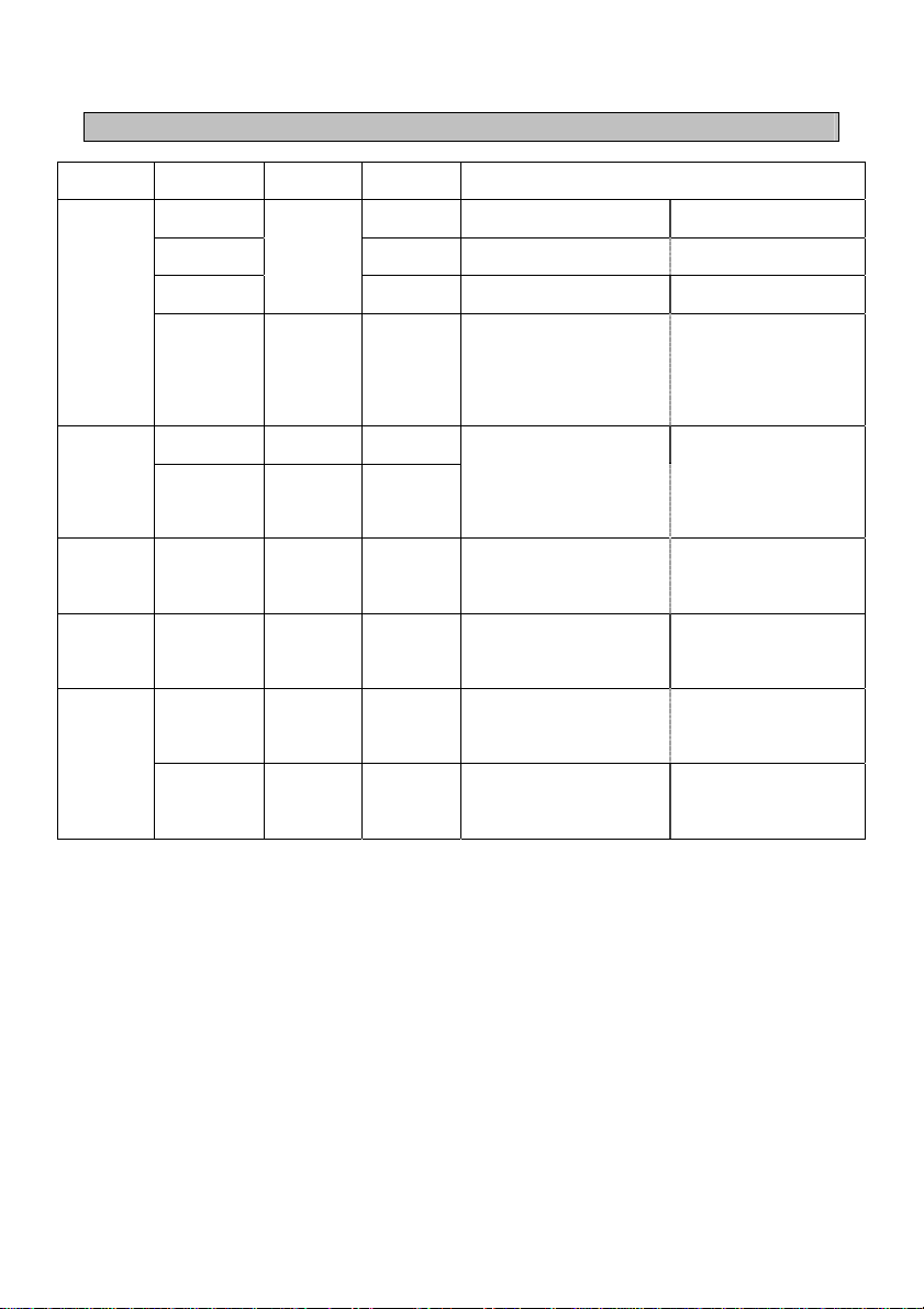
別途ご準備必要な部品
Parts required additionally
メーカー
Manufacturer
日産
NISSAN
トヨタ
TOYOTA
マツダ
MAZDA
三菱
MITSUBISHI
スバル
SUBARU
上記以外の準備部品
車種
Vehicle model
BNR32 NM032SDMC
BCNR33 NM042SDMC
BNR34
Z33 VQ35DE NM072SDMC
JZX90/100/110
JZA70
JZA80 2JZ-GTE TM042SDMC
FD3S 13B-REW ZM022SDMC
CN/CP/CT9A 4G63 MM022SDMC
GC8 EJ20 FM012SDMC
GDB EJ20 FM022SDMC
エンジン形式
Engine model
RB26DETT
1JZ-GTE TM032SDMC
商品番号
Parts No.
NM052SDMC
Parts required to be prepared
レリーズベアリング
Release bearing
レリーズベアリング
Release bearing
レリーズベアリング
Release bearing
フライホイール取付けボルト
Flywheel mounting bolt
レリーズベアリング
Release bearing
フライホイール取付けボルト
Flywheel mounting bolt
レリーズベアリング
Release bearing
カウンターウェイト
Counterweight
レリーズベアリング
Release bearing
フライホイール取付けボルト
Flywheel mounting bolt
レリーズベアリング
Release bearing
パイロットベアリング
Pilot bearing
レリーズベアリング
Release bearing
パイロットベアリング
Pilot bearing
レリーズベアリング
Release bearing
準備必要部品
純正装着部品
Genuine parts
純正装着部品
Genuine parts
純正装着部品
Genuine parts
ニッサン純正
Nissan genuine parts
8
8 pcs.
純正装着部品
Genuine parts
トヨタ純正 90910-02103
TOYOTA genuine parts
8本
8 pcs.
純正装着部品
Genuine parts
マツダ純正
MAZDA genuine parts
純正装着部品
Genuine parts
純正装着部品
Genuine parts
純正装着備品
Genuine parts
純正装着部品
Genuine parts
純正装着部品
Genuine parts
純正装着部品
Genuine parts
純正装着部品
Genuine parts
Parts to be prepared other than the above ones
1.
プッシュ系日産車については12ページに記載のレリーズスリーブが必要となります。
Release bearings shown in page 12 are required for the push type Nissan vehicles.
2.
全車レリーズベアリングを新品に交換されることを推奨します。
We recommend you replace the release bearing f or al l veh ic le models with a new one.
3.
全車フライホイール取付けボルトを新品に交換されることを推奨します。
上表に記載の無い車種については、製品に同梱のボルトを使用下さい。
We recommend you replace the flywheel moun ti ng bolts for all vehicle models with new on es .
For the vehicle models not shown in the table above, use bolts enclosed with the product .
4.
パイロットベアリングについて特に記載の無い車種で、クランク側にベアリングが入っている車種
においても、クラッチ交換の機会に新品に交換されることをお勧めします。
As for the vehicle model that no des c ri ption is provided for the pilot bearing and a bea ring is
incorporated into the crank, we recommend you repl ac e th e pi lot bearing with a new one at the
time of replacement of the clutch.
12315-30P01
本
N351-11-521
M330 - 7 -
Page 8

取付け方法
1.
Disassembly of kit
P6
構成図⑧のボルト
Loosen the bolt No. 8
!
2. パイロットベアリングの取付け
Installation of pilot bearing
フライホイールにパイロットベアリングが必要となる車種については新品の純正部品を準備していた
だき取付けてください。
(7ページ一覧表を参照ください。)
As for the vehicle model that the pilo t be arin g is requ ire d for th e flywheel, prepare the new and genuine
parts, and install them.
(Refer to the list in page 7.)
3.
Installation of flywheel (F/W)
1)
Nissan, Toyota, Subaru, and Mitsubishi vehicles
Installation procedure
キットの分解
注意
CAUTION
フライホイール(F/W)の取付け
日産車、トヨタ車、スバル車、三菱車
構成図⑦の
さい。
At the time of installation of the flywheel No. 7
bolt) specified on the list.
トヨタ車のクランクボルトのねじ山部には、必ずアドヘシブ
い。
塗布せずそのまま締め付けるとエンジンオイルがボルト穴よりにじみ出ます。
Be sure to apply "Adhesive 1324" to the thread ridges of the crank bolt for the Toyota veh icle
before tightening it.
Otherwise, engine oil will ooze from the bol t ho le.
クランクボルトは、対角順に数回に分けて、均等に締め付け、最後に規定トルクに合わせて、
本締めを行って下さい。
Tighten the crank bolt diagonally not at a ti m e, but for several times with equal force. Fi nally,
tighten up it with the specified torque.
その後、P6構成図
って取付けて下さい。
Then, install the flywheel No. 7
issued by the vehicle manufacturer.
を緩め、キットを分解して下さい。
and disassemble the kit.
P6
F/W
構成図⑫のナット
下さい。
万一緩めてしまった場合は、ネジロック剤(高強度用)を塗布し規定トルク
75 Nm {6.6〜7.6 kgm}
〜
DO NOT loosen the bolt No. 12
before delivery.
If it is loosened by mistake, apply a sc r ew lock agent (strong) to it, and tighten it
with the specified torque 65 Nm to 75 Nm {6.6 to 7.6 kgm}
の取付けは一覧表にて指定のクランクボルト(FW取付けボルト)を必ず御使用下
NO.
⑦のフライホイール
は、正規トルクで締付けて出荷していますので緩めないで
で締付けて下さい。
that was tightened with the specified torque
, be sure to use the crank bolt (flywheel mounting
をクランクシャフトにカーメーカー発行の整備書に従
to the crank shaft in accordance wit h the maintenance manual
.
1324
を塗布して締め付けてくださ
65
M330 - 8 -
Page 9
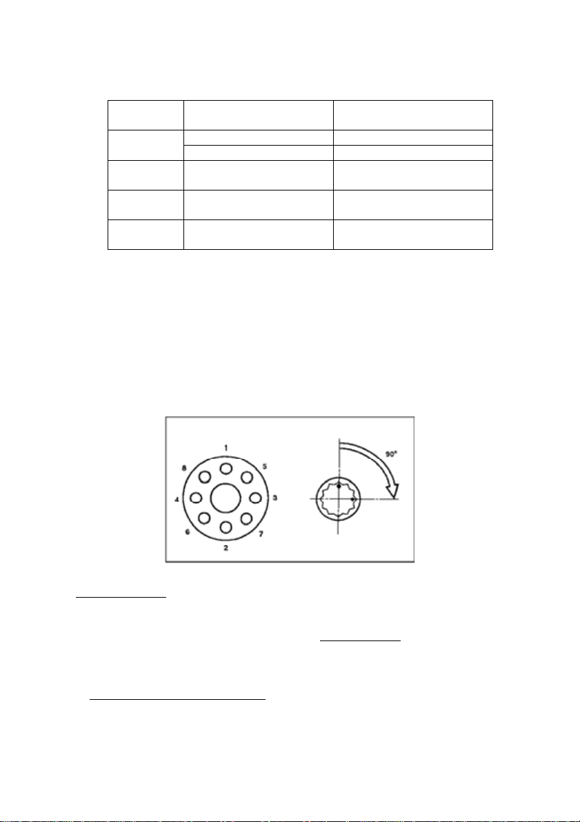
クランクボルト締付トルク一覧
Crank bolt tightening torque list
メーカー名
Manufacturer
日産
NISSAN
トヨタ
TOYOTA
スバル
SUBARU
三菱
MITSUBISHI
エンジン型式
Engine model
RB26DETT 142〜152 Nm {14.5〜15.5 kgm}
VQ35DE 83〜93 Nm {8.5〜9.5 kgm}
1JZ-GTE, 2JZ-GTE
EJ20 69〜78 Nm {7〜8 kgm}
4G63 127〜137 Nm {13〜14 kgm}
締付トルク
Tightening torque
49 Nm {5.0kgm} 注1
Note 1
注 1. トヨタ1JZ,2JZ については上表のトルクで締付けた後、下記締付けを行います。(下記図面
参照)
Note 1. As for the Toyota 1JZ and 2JZ, tightening below must be carried out after the crank bolts are
tightened with the tightening torque shown in the table above. (See the drawing below.)
1) クランクボルトの頭部にペイントマークを付ける。
Paint the bolt-head with a color paint for marking.
2)
ペイントマークを目安にして、各クランクボルトを対角順に90°締付ける。
Tighten the crank bolt a further 90 degree relative the paint mark.
3) ペイントマークが全て右側にあることを確認する。
Check the paint mark located on the right s id e.
2)
マツダ車
P6
構成図⑦の
定します。
F/W
に純正部品のカウンターウェイト(7ページ参照)を付属の専用ボルトにて固
Mazda vehicle
Fix the Mazda genuine counterweight (see page 7) to the flywheel No. 7
with the supplied special
bolts.
☆ フライホイール取付けボルトは、対角順に数回に分けて、均等に締め付け、最後に規定トルク
に合わせて、本締めを行って下さい。
規定トルク54〜
F/W
その後
い。
74 Nm {5.5〜7.5 kgm}
をエキセントリックシャフトにカーメーカー発行の整備書に従って取付けて下さ
Tighten the flywheel mounting bolts dia go nally not at a time, but for several times with equ al
force. Finally, tighten up it with the s pec i f i ed torqu e.
M330 - 9 -
Page 10
Specified torque: From 54 to 74 Nm {from 5.5 to 7.5 kgm}
Then, install the flywheel to the Ecc e ntric shaft in accordance with the maint ena nc e man ua l
issued by the vehicle manufacturer.
4.
各部品の組み込み
Assembly of parts
《組立順序》P6の構成図に従って各部品を組み込みます。
ドリブンプレート(カーボン)→センタープレート→センターハブダンパー→
ドリブンプレート(カーボン)→プレッシャープレート→ピボットリング→クラッチカバー
組み込み時、①②③⑦の位置決めは、外周部にペイントされた青色合マーク
ドリブンプレート(カーボン)に裏表はありません。
«Assembly order» Assemble the parts in accordance with the structural drawing in page 6.
Driven plate (carbon) → Center plate → Center hub damper→ Driven plate (carbon) → Pressure plate
Pivot ring → Clutch cover Assy
→
At the time of assembly, be sure to match t he painted blue marks
of the [1], [2], [3] and [7].
Driven plate (carbon) is the same on the both sides .
!
!
!
5.
!
注意
CAUTION
注意
CAUTION
注意
CAUTION
エンジン側パイロットに、芯出しバーをセットしP6構成図⑤のセンターハブダンパー
を出し、P6構成図①のクラッチカバー
芯出しバーには純正のメインドライブシャフトの使用を推奨します。
Set up the center bar to the pilot at engine side, and center the center hub damper No. 5
the clutch cover Assy No. 1.
The genuine main drive shaft is recommended for this process.
注意
CAUTION
センターハブダンパーには方向がありますので、向きを間違えないよう十分注意
して下さい。
EXEDY』
『
上記識別文字が、カバー側から見える方向に組み込む。
Be careful of the direction/location of th e c enter hub damper.
"EXEDY"
It should be assembled in such t he di rec tion that the identification ma rk above can
be seen from the cover side.
合マークが合っていないと回転バランスが崩れ異音、振動が発生し、また出力低
下の原因にもなります。
If the marking is not met, it will cause unbalance, noise and vibration problems.
スプラインハブのグリスアップはディスク及びシャフトに純正指定グリスを塗布
後、シャフトにディスクを通してはみ出た余分なグリスは滑りの原因になります
ので必ず拭き取って下さい。
Apply grease specified by the vehicle manufacturer to the spline hub then insert
the shaft and wipe away any grease which is f orc ed out .
P6
構成図⑤のセンターハブダンパー
が困難になり、またディスクの破損の原因になります。
Failure in centering of the center hub dam p er No . 5
assembly of the transmission and da ma ge to the disc.
Assy
を締め付け固定します。
を必ず合せて下さい。
on the outer diameter for positioni ng
のセンターが合っていないと、
will lead to difficulty in the
Assy
のセンター
. Tighten
T/M
組み付け
M330 - 10 -
Page 11
P6
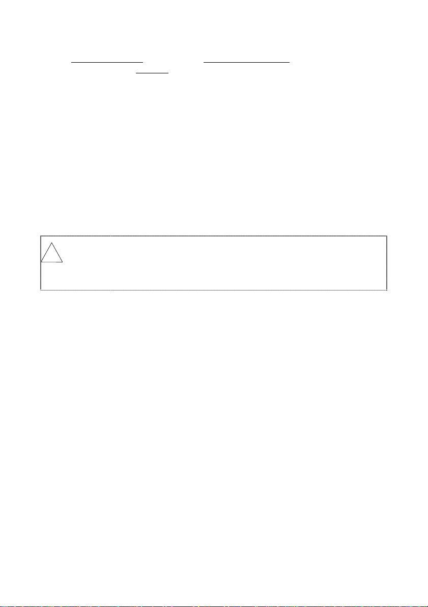
構成図⑧のボルト
Specified torque of bolt No. 8
ボ ルトの締め付けが不均一な場合(一気にしめた場合)切れ不良やジャダー発生の原因に
なります。
Unequal bolt tightening will cause disengagement problems and judder/shudder.
6. ボルト締め付け後、レバーの高さが均等にそろっているか確認して下さい。
もし、不均一な場合、再度「項目3」よりやり直して下さい。
Confirm that lever height is equal afte r tigh tening. If it is not equal, then restart from item 3.
T/M
7.
Replace the T/M.
8.
Stroking adjustment
《アドバイス》
を再組付けします。
レリーズベアリングは純正の新品に交換し、各摺動部には純正指定のグリスを適量塗布して下さい。
詳しくはカーメーカー発行の整備書に従って、なるべく水平な状態で作業下さい。
Purchase a new release bearing and apply grease to slid in g su rfa c e.
Follow the maintenance manual iss ued by the vehicle manufacturer.
注意
CAUTION
!
ストローク調整
当キットに交換した場合、ペダル位置(切れ点及び繋がり点)が変化する場合があります。この場
合はペダル調整を行って下さい。
詳しくはカーメーカー発行の整備書に従って下さい。
After installing of this kit, the pedal po sition (engagement or disengagement point) may change.
Adjust the pedal according to the maintenance manual issued by the vehicle manufa cturer.
«Advice»
z
ペダル位置を深くしたい場合(床側に近付ける)
マスターシリンダー部のプッシュロッドを短く調整し、フリー時のペダル高さを下げる方向に調整
する。
If the pedal position should be mo ved t oward s the floor, adjust the push-rod of the master cyl in de r
in the manner the pedal height is down in free position.
z
ペダル位置を高くしたい場合(床から遠くする)
上記と逆の方向に調整する。
If the pedal position should be moved away from the floor, adjust the push-ro d in the oppo site to
the above.
T/M
ライン部をこじったり、変形させない様十分注意下さい。切れ不良やディスク破
損の原因になります。
Do not hit the spline teeth with the edge of the main drive shaft. It will cause
disengagement problems or damage to th e c enter hub damper.
締め付けトルク:27〜
:
組み付け時、メインドライブシャフト先端で、センターハブダンパーのスプ
29Nm {2.8〜3.0kgm}
M330 - 11 -
Page 12
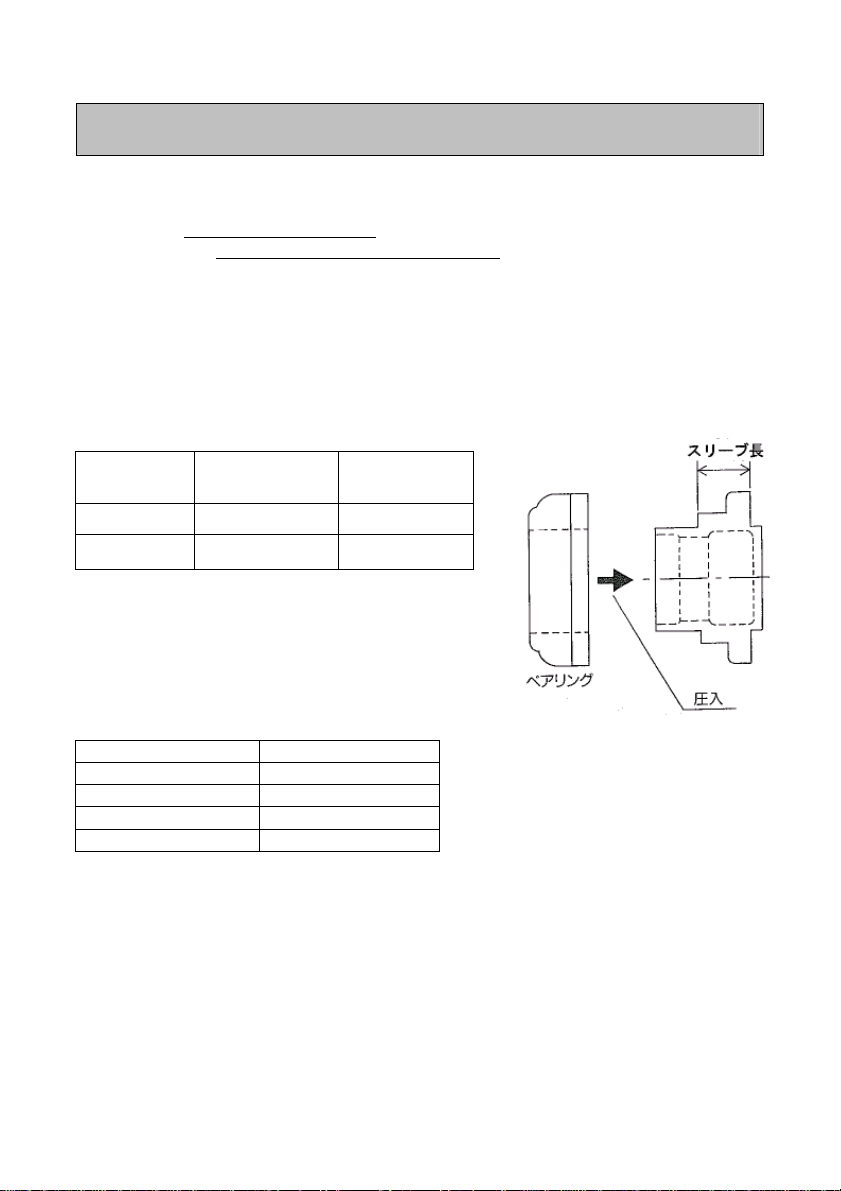
レリーズベアリング及びクラッチスリーブ(プッシュ式用)
Release bearing and clutch sleeve (for push type)
z
レリーズベアリングは当社指定品を別途購入しご準備下さい。
Additionally purchase the releas e bearing specified by us.
指定部品:日産純正部品
30502-14601
Parts specified: Nissan gen uin e part s num ber 30502-14601
z
クラッチスリーブの選択
クラッチスリーブは各車両別に、純正クラッチ装着時(新品時)とレリーズフォークの傾きが同じ
になるスリーブ長さのものを御使用下さい。
Selection of clutch sleeve
Use the clutch sleeve whose sle eve len gth allows the same inclination of the release fork as that in
the case the genuine clutch (new one) is inst alled, appropriate for each vehicle.
【日産車】
[Nissan vehicle]
クラッチ品番
Clutch model
NM03 R32 (RB26DETT) 14〜16 mm
NM07 Z33 (VQ35DE) 純正装着部品
適応車種
Applicable vehicle
model
推奨スリーブ長
Recommended sleeve
length
Genuine parts
* 車輌によって個体差が有りますので現車での確認をお願い
します。
Since all the vehicles are indi vid ual, check the clutches
and release bearings with installed to th em ac tually.
日産純正部品番号(クラッチスリーブ)
Nissan genuine parts number (clutch sleeve)
30501-A3800 (12 mm) 30501-S0160 (22 mm)
30501-N1601 (14 mm) 30501-K0404 (24 mm)
30501-U0200 (16 mm) 30501-K0510 (26 mm)
30501-S0200 (18 mm) 30501-N1600 (28 mm)
30501-B6000 (20 mm) 30501-N8400 (30 mm)
* プル式車は、純正指定のプルベアリングの新品に交換下さい。(変更不要)
For the pull type vehicles, repl ace the bearing with the genuine new pull typ e bea r ing . (No
modification is required.)
9.
スバルインプレッサ
GDB
インプレッサには急激なクラッチ結合を防ぐ為のオリフィス機構が設けられています。
GDB
について
このオリフィス機構がカーボンの早期磨耗やすべりを誘発することがありますので、下記要領でオ
リフィスを機能不能にしてください。(
P13
参照)
Subaru Impreza GDB
The GDB Impreza is equipped with the orifice mechanism in order to prevent an abrupt clutch
engagement.
Sleeve length
Bearing
Press-in
M330 - 12 -
Page 13
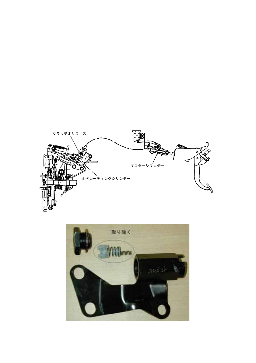
Since this orifice mechanism may ca us e prem ature wear of carbon or a slip, disable it by
implementing the steps shown below.
1)
クラッチオペレーティングシリンダー横のオリフィス本体を取り外す。
Remove the orifice on the side of the clutch opera ting cylinder.
2)
オリフィス機構のオペレーティングシリンダー側にあるねじを緩めます。
このとき内部にスプリングが入っていますのでご注意ください。
Loosen the screw on the operating cylinder side of the orifice mechanism.
At this time, pay attention to the spring incorporated in it.
3)
内臓部品(スプリング2個、プラスチック部品2個)全てを取り除きます。
Remove all the built-in parts (two springs and two pl astic parts).
4)
パッキンを忘れないようにねじを締め付けます。
Pay attention not to omit the gasket, and t ig hte n th e s c r ew.
5)
車両に元通り組付け、エア抜きを実施ください。
Re-install the orifice mechanism to the vehicle, and bleed air.
Clutch orifice
Master cylinder
Operating cylinder
Remove
M330 - 13 -
Page 14

使用上の注意事項 Caution during operation
1.
!
2.
!
3.
使用状況によっては、発進時に若干の鳴きやジャダーが出る場合がありますが特に異常ではありま
せん。
In the early stage, it is not abno rm a l if subtle noise or chattering oc c urs depending on the operating
conditions.
4.
クラッチの構造上、クラッチを切っている時に多板クラッチ特有のカラカラ音が発生しますが異常
ではありません。
Due to the clutch design, the mu ltiple disc clutch may cause a rat tle noise when disengaged. This is
not an abnormal condition.
5.
!
6.
!
注意
CAUTION
注意
CAUTION
警告
WARNING
警告
WARNING
クラッチ取り付け後は、必ず慣らし運転(P2参照)を行って下さい。
各摩擦面が全面当たりしない状態で過酷な使用をすると、すべりや部分的な焼き
付きを生じ、ジャダーや寿命低下につながります。
After installation, drive carefu lly and gently. (See page 2.)
If the clutch is used in a condition where the friction surface is not cont ac ting fully
with the mating surface, it will cause slip, burning, judder/shudder or short life.
多板クラッチの性質上、新品時と慣らし後ではペダル位置が変化し、半クラッチ
操作性に変化がありますが特に異常ではありません。
慣らし後に再度ストローク調整する事を推奨します。
It is recommended to re-adjust the stroke af te r t he break in period. Due to the
nature of the multiple disc clutc h, hal f en gag ed clutch operation will also be
affected after break in period but this is a norm al s ymp to m .
車輌側のレリーズコントロール系は指定箇所を除き一切の改造を行わないで下
さい。
(純正の状態で使用出来るように設定しています。)
特に、クラッチオペレーター内部のスプリングは取り除かないで下さい。
レリーズベアリングに作用するプリロードが無くなり、使用中にベアリング抜け
につながります。(プルタイプの場合)
Do not change any release control function of the vehicle except fo r the specified
positions.
(The clutch is used under normal con dit ion.)
Especially, DO NOT remove the sp ring in th e c lutch operator. Otherwise, the
preload working on the release bearing will be lost , le ading to release of the
bearing during usage (for the pull type).
本製品は競技専用に設計されていますので、純正品に比べ踏力が重く、発 進操作
が難しくなりますので、十分な慣れが必要です。
体力、技量に自信のない方は使用をご遠慮下さい。
This clutch system is specially designed for racing purposes, therefore pedal
effort is slightly heavier and start operation is more difficult than standa rd m anu al
clutch products.
Avoid using if you are not completely confident with your driving technique and
physical strength.
M330 - 14 -
Page 15
7.
注意
CAUTION
!
《アドバイス》
«Advice»
新品状態のレリーズフォークの位置を記録しておいて、その変化量を常に管理して摩擦材の摩耗量を
把握し、早めのオーバーホールを実施する事が長く性能を維持する秘訣です。
Record the new release fork position and confirm its variation. Facing wear amount can then be
foreseeable. Preventative maintenance before the discs are worn out is a key factor to maintain
steady performance.
ディスクの使用限度;摩擦材厚さ 4.7mm
Maximum facing wear: Facing thickness 4.7 mm
8.
警告
WARNING
!
9.
警告
WARNING
!
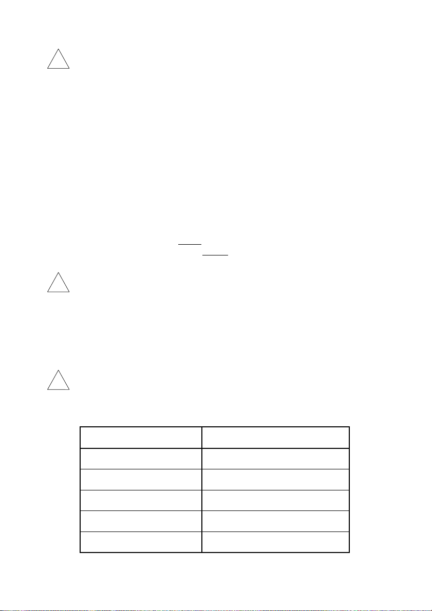
《使用限界表》
«Operation limit list»
最大入力回転速度
Max. engine rpm
最大実用トルク
Max. engine torque
ディスク摩耗限界
Max. disc wear
最高摩擦面温度
Max. friction surface temperature
最大レリーズストローク量
Max. release stroke
多板クラッチの性質上、操作方法、使用環境によって摩擦材の寿命は著しく低下
する事があります。
特にゼロ発進を多用する競技(ドラッグレース等)では、摩擦材の消耗が早い為
まめに点検して下さい。
The life of a multiple disc clutch may be adversely affected by driving technique
and driving conditions.
Especially, the friction material is worn prematurely in a racing which
necessitates frequent abrupt start ope ration (for example, drag race). Check it
frequently.
多板クラッチの構造上、半クラッチを多用するとクラッチ内部が高温になり構造
部品の膨張、変形等で切れ量が減少し一時的に切れが悪化する事があります。
この場合走行を中止し一度冷やしてから運転を行って下さい。
Due to the nature of the multiple disc clu tc h, if the clutch is used in the half
engaged position for extended periods of time, the clutch set will generate high
temperatures. This high heat c reates expansion or deformation whic h c aus es
disengagement problems temporarily or permanently.
Stop driving and allow the clutch to coo l down.
本製品は下記の使用限界を超えて使用した場合、破損又は走行不能となり、人命
に関わる事故に繋がる恐れが有りますので、絶対に行わないで下さい。
Do not over use the clutch beyond the fol lo w ing limits.
項目
Item
(新品時 5.5mm)
(At new 5.5 mm)
許容限界値
Limit
12000 r/mim
667 Nm {68 kgm}
1.7 mm迄
合計
Total 1.7 mm
800°C
9.0 mm
M330 - 15 -
Page 16

10.
11.
12.
!
!
!
警告
WARNING
警告
WARNING
警告
WARNING
各プレート類及びフライホイールは、一切の修正加工を行わないで下さい。各
部品の強度が低下し破損する恐れが有り人命に関わる事故に繋がる恐れがあり
ます。
Do not machine any part of this product, ot herwise the strength of each part will
be reduced and may fail prematurely.
ボルト締結部は締付けが緩くても強くても緩みや折損に繋がりますので必ず本
書にて規定の締付けトルクで締付けて下さい。
また部品の合せ面には異物の噛み込み等の無い様に洗浄を行って下さい。
同様に緩みや破損の原因になります。
The bolts have to be tightened at the speci fied torque.
The mating surfaces should be cleaned , wiped with a clean towel to remove
any foreign waste. They may affect the pe rform a nc e of the clutch.
ボルト類は重要品質部品ですので必ず付属の部品か本書にて指定の純正部品を
使用して下さい。
指定以外のものでは、必要な強度が得られず破損し人命に関わる事故に繋がる
恐れがあります。
また一度使用したものを緩めた場合、新品に交換して下さい。
The bolts are the very important parts. Use eit her ge nuine parts or the bolts
included as auxiliary parts in the box.
Do not reuse the old bolts after un-tighte ni ng.
M330 - 16 -
Page 17

お問い合わせ先
For further information
(株)エクセディ スポーツ
BC
EXEDY Corporation Sports BC
572-0822
〒
大阪府寝屋川市木田元宮
1-1-1
1-1-1 Kidamotomiya, Neyagawa-shi, Osaka 572-0822 , J ap an
TEL:072-822-1246FAX:072-821-6541
E-mail:[email protected]
Exedy USA
8601 Haggerty Road South
Belleville, MI 48111
TEL: (800) 346-6091 FAX: (734) 397-7300
E-mail: [email protected]
EXEDY AUSTRALIA PTY LTD
21 Five ways Boulevard Keys borough,
Victoria 3173, AUSTRALI A
TEL: 61-3-9701-5556 FAX: 61-3-9701-5684
EXEDY Clutch Europe Ltd.
Unit 2, Rokeby Court, Manor Park,
Runcom, Cheshire WA7 1RW, UK
TEL: 44-1928-571850 FAX: 44-1928-571852
M330 - 17 -
 Loading...