

Page 1
1
NSA 2010
TABLE DE MIXAGE PROFESSIONNELLE avec
interface USB
STEREO SOUND MIXER with USB
INTERFACE
NOTICE D’UTILISATION
USER MANUAL
2
FACE AVANT
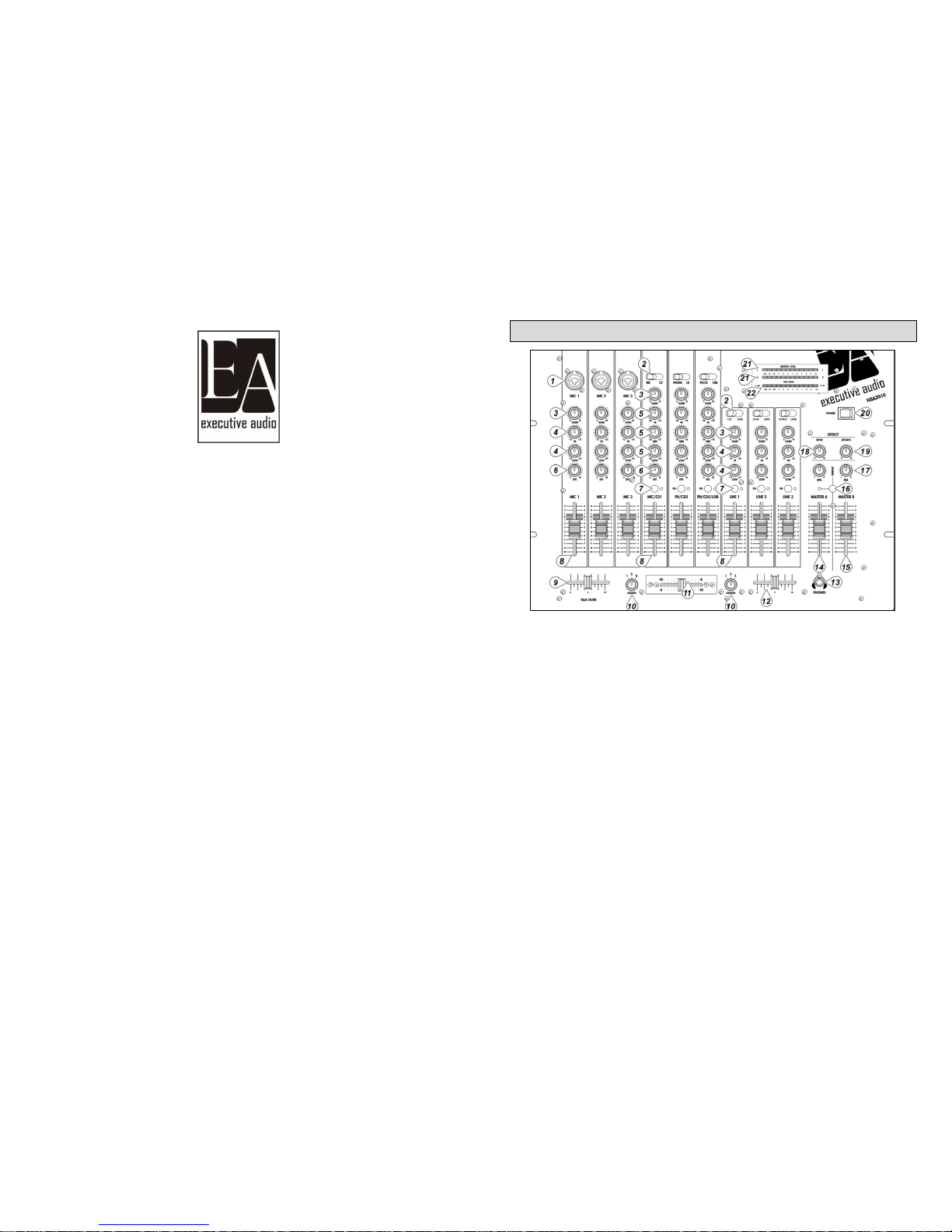
1. ENTREES MICRO
Trois entrées micro sur embase combo XLR 3 broches symétriques ou jack 6.35
asymétriques
2. SELECTEUR D’ENTREE
Chaque canal à deux entrées possibles. Ce commutateur vous permet de faire votre
choix. Tous les canaux ont ainsi une entrée double : PH/CD1, PHONO/CD 2 et3 et
LINE1, LINE/CD 2, 3.
3. GAIN
Réglage du niveau d’entrée de la voie, un bon réglage permet d’éviter la distorsion
4. EGALISATION DES VOIES MICRO ET LINE
Deux correcteurs basse/aigu à +- 12 db
5. EGALISATION DES VOIES MUSIQUE
Trois correcteurs basse/médium/aigu à + 12 db/-26 db
6. EFFET
Contrôle du niveau d’effet sur chaque voie, ce contrôle est post-fader
7. PRE ECOUTE
Ces boutons permettent la pré-écoute de la source au casque. La LED s'allume quand
la fonction est activée
8. CONTROLE DU VOLUME DE CHAQUE VOIE
Ces faders permettent le réglage du niveau du volume. Le fader du canal stéréo
contrôle à la fois le signal droit et gauche en même temps.
Page 2
3
9. TALK OVER
Réglage du talk over sur les voies micro. Le niveau musical baisse automatiquement et
laisse la priorité au micro. Réglage 0 db (off) à 20 db
10. SELECTEUR CROSS FADER
Assignation en x ou y des trois voies PH/CD sur le crossfader
11. CROSS FADER
Crossfader interchangeable, permet le fondu enchaîné des voies sélectionnées en x ou
y
12. NIVEAU CASQUE
Potentiomètre de réglage du niveau casque
13. SORTIE CASQUE
Embase jack 6.35 pour la sortie de pré écoute au casque
14. MASTER A
Réglage du niveau de sortie master, sur les connecteurs XLR symétriques et jack 6.35
asymétrique
15. MASTER B
Réglage du niveau de sortie master sur les connecteurs RCA asymétriques
16. DISPLAY SWITCH
Sélecteur de visualisation sur les vumètres des master A ou B.
Commutateur relevé : Sortie signal MASTER A
Commutateur enfoncé : Sortie signal MASTER B
17. BALANCE
Réglage de balance droite/gauche des master A et B
18. EFFECT SEND
Réglage du niveau de sortie effet
19. EFFECT RETURN
Réglage du niveau d’entrée effet
20. POWER
Interrupteur de marche/arrêt
Remarque : toujours mettre en marche la table de mixage avant l’amplificateur
21. AFFICHAGE NIVEAU MASTER
L'affichage indique le niveau du signal MASTER A et B suite à votre sélection.
22. AFFICHAGE CUE
Indication du niveau du signal d'entrée suite à la sélection que vous avez faite à l'aide
des boutons CUE.
4
FACE ARRIERE
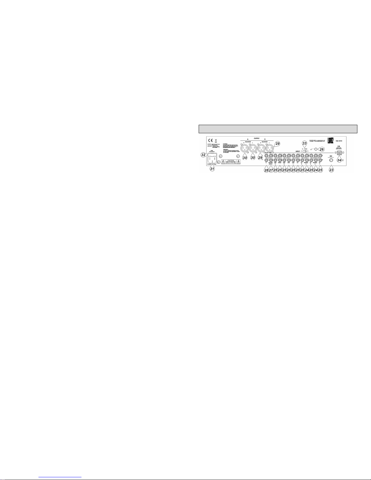
23. ENTREE MICRO
1 Entrée Jack 6.35 permet de connecter votre micro à la table de mixage.
24. ENTREE PHONO
Entrées asymétriques sur connecteur RCA pour platines vinyles.
25. ENTREE CD /LINE
Entrées asymétriques sur connecteur RCA des différentes sources.
26. GND
Raccord de la masse des platines vinyles.
27. RETURN EFFECT
Connexion d'un équaliseur ou d'une chambre d'echo
28. SORTIE MASTER B
Ces sorties asymétriques sur connecteurs RCA sont contrôlées par le fader MASTER
B.
29. SORTIE MASTER B
Ces sorties symétriques sur connecteurs XLR 3 broches sont contrôlées par le fader
MASTER B.
30. SORTIE MASTER A
Ces sorties symétriques sur connecteur XLR 3 broches sont contrôlées par le fader
MASTER A.
31. ALIMENTATION SECTEUR
Fiche standard IEC de raccordement secteur, 220/240V
Remarque : Avant de brancher votre appareil, assurez-vous que sa tension
corresponde à la tension en vigueur.
32. FUSIBLE
Logement du fusible de protection. Toujours remplacer ce fusible par un autre de
même valeur.
33. PHONO/CD
Ce commutateur permet de sélectionner soit l'entrée PHONO ou soit l'entrée CD
34. CONNECTEUR USB
Entrée et sortie USB pour la lecture des fichiers Mp3 (ou toute autre source audio)
stockés sur votre ordinateur ou pour l'enregistrement de vos performances sur votre
ordinateur. Ce connecteur permet ainsi de recevoir ou d'envoyer des données via votre
Page 3
5
ordinateur. Le connecteur USB envoie les signaux audio via le canal
PHONO/CD/USB.
Remarque : Quand vous branchez ou débranchez le câble USB, assurez-vous de
toujours avoir le fader du canal LINE/CD/USB en position la plus basse.
CARACTERISTIQUES TECHNIQUES
SENSIBILITE/IMPEDANCE : DJ/MICRO : 3mV/1Kohms
PHONO : 3mV/51Kohms
LINE/CD : 150mV/100Kohms
NIVEAU DE SORTIE
MASTER B (sortie maxi 8V) : 775mV/600ohms asymétrique
MASTER A/B (sortie maxi 8V) : 775mV/600ohms symétrique
CASQUE : 380mV/80ohms
EFFET : SEND (sortie maxi 8V) : 775mV/600ohms
RETURN : 775mV/100Kohms
REPONSE EN FREQUENCE : 20 Hz≈20KHz±0.5dB (RIAA±2dB)
DISTORTION HARMONIQUE TOTALE : 0.01%
SEPARATION STEREO: > 45dB
RAPPORT SIGNAL/BRUIT : DJ MIC : 80dB
PHONO : 70dB / LINE/CD : 85dB
RETURN : 85dB
CONTROLE DE TONALITE
MICRO & LINE 1-3
Boost/Cut@center Frequency : ±12dB@100Hz, 10KHz
PHONO/CD
Boost@Center Frequency : +12dB@100Hz, 1KHz, 10KHz
Special Cut@Center Frequency : Aigu : –26dB@ au dessus 10KHz
Medium : –26dB@ 1KHz
Basse : –26dB@ en dessous 100Hz
TALKOVER : 0 à –20dB
INTERFACE USB
Conversion signal : Analogique Digital ou Digital Analogique : 16 bit
Lecture : Distortion : < 0.05% / Ratio Bruit : 80dB / Enregistrement : Distortion : <
0.1%
Interface : USB1.1 ou USB2.0, fonction lecture et enregistrement
DIMENSIONS : 482 x 348 x 115mm POIDS : 6,5 Kg
Attention: L'appareil ne doit jamais être en contact avec de l'eau ou tout autre liquide.
54IN816.011409
6
FRONT PANEL
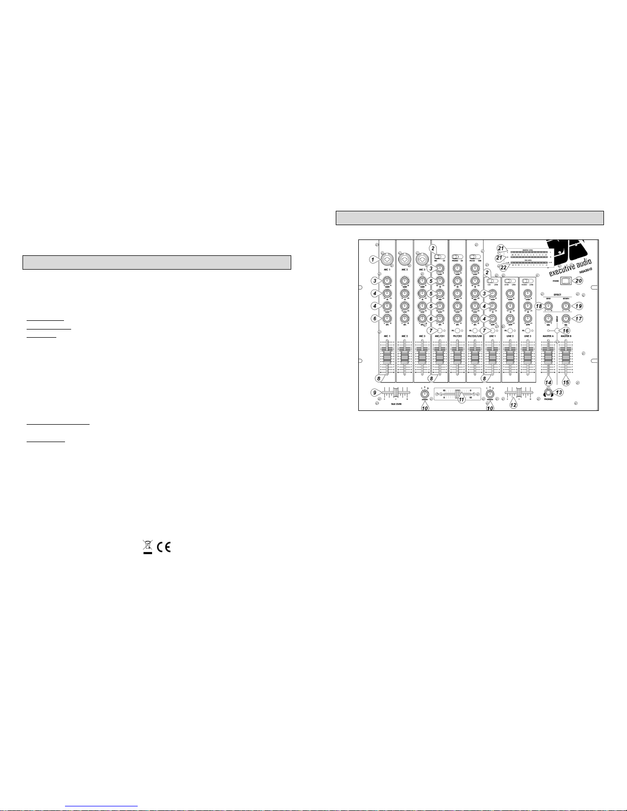
1. MICrophone Input
Three Combination XLR & 1/4“ jack sockets are mounted on the front face of
the mixer for connecting your microphone and offer both balanced or unbalanced
microphone connections..
2. Input Selector
Each music input channels has two input options. This switch lets you select
which of the inputs plugged into the channel you wish to use. All input channels
are dual with Channel PH/CD1, 2&3 PHONO/CD and Channels LINE1, 2&3
LINE/CD.
3. GAIN Controls
Correct setting of the controls for input GAIN for every channel is crucial for
getting a good, strong signal without noise or distortion.
4. MIC & LINE1-3 Channel EQ
All Microphone channels & channel LINE 1-3 have a 2-band equalizer for tone
shaping. The EQ controls have fixed frequencies and a boost/cut range of +/12dB.
5. Music Channel EQ
All music channels have a 3-band equalizer for tone shaping. The EQ controls
have fixed frequencies and a boost/cut range of +12/-26dB.
Page 4
7
6. Channel EFF Control
Channel EFF controls ‘tap’ an adjustable portion of the each monaural channel
signal and send it to their correspondent SEND output in the master section. The
control works post-fade.
7. CUE Switch with Indicator
These switches determine which source is heard in the headphones, the LED
illuminates when the CUE switch is on.
8. Channel Level Control
The channel fader adjusts the overall volume of the channel. The faders of the
stereo channels control both left and right signal at same time.
9. TALKOVER Control
When the Master microphone is activate all other inputs will be automatically
attenuated. This control pre-sets the level of which the main music program will
be attenuated.
Attenuation range: 0dB (OFF) to 20dB.
To disable the override facility, simply turn the control fully left.
10. Crossfader ASSIGN Switch
Any of the three PH/CD channels can be assigned to either side of the crossfader
by the setting of these switches.
NOTE: If the same channel is assigned to both sides of the crossfader at either
extreme that channel will be muted but the channel will be live when the
crossfader at it“s center position. This setting can give the effect of ‘fader dub
fading’ when crossfader is used from it‘s center to either extreme.
11. Removeable CROSSFADER
This 45mm crossfader is fully assignable to any of the four main music channels
set by the ASSIGN switches.
12. Headphone LEVE Control
This control varies the volume in your headphones, the volume of the signal
heard through the headphones.
13 PHONES
This is a 1/4” stereo jack socket mounted on the front face of the mixer for you to
attach
14. MASTER A Level
This slider controls the overall output level leaving the Master A balanced XLR
and unbalanced 1/4” phone jack outputs.
15. MASTER B Level
This slider controls the overall output level leaving the Master B unbalanced
RCA jack outputs. The program content of the BOOTH output is the same as the
MATER A output.
16. DISPLAY Switch
Either the Master A or B Output signal can be showed on the MASTER VU
meter depending on the position of this switch.
Switch released: Master A Output Signal
Switch depressed: Master B Output Signal
8
17. BALANCE Control
This control is used to set the Stereo Balance of the master A&B Left, Right
Outputs.
The master Output program can be fully panned to the Left or Right.
18. Effect SEND Output Control
The control can be adjusted overall output volume of the EFF SEND outputs but
is also affected by the channel EFF control.
19. Effect RETURN Control
The stereo EFF RETURN inputs can be added to the master signal with the EFF
RETURN controls.
20. POWER Switch
This switches the AC power to the mixer ON or OFF.
Note: Be sure to switch on the power to your mixer before switching on the
amplification system.
21. Output Program Level Display
The display shows the signal level of the mixer master A or master B you have
selected with the DISPLAY button.
22. PFL Level Display
The display shows the signal level of the mixer input you have selected with the
Cue buttons.
REAR PANEL
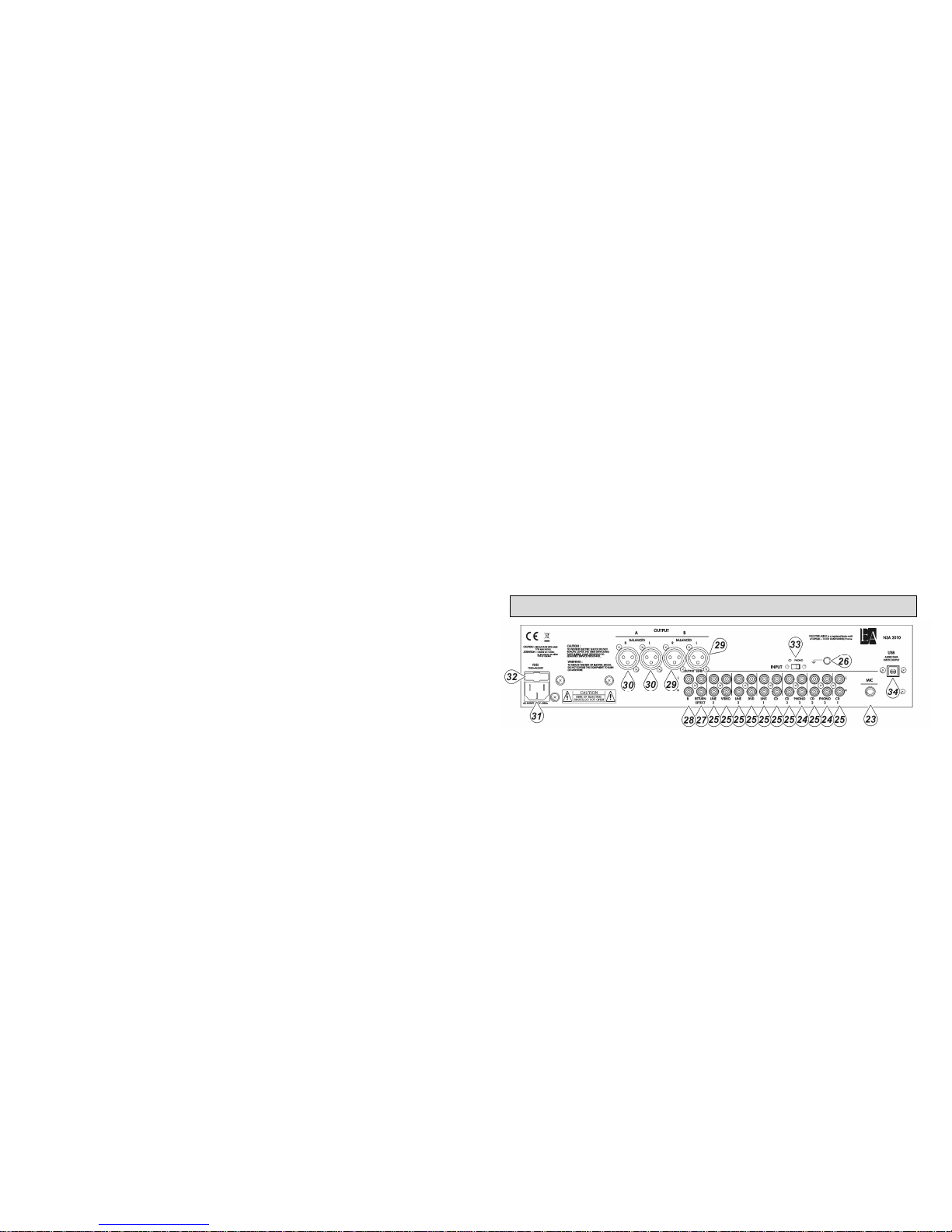
23. MICrophone Input
One 1/4“ jack socket is mounted on the rear panel of the mixer for connecting
your microphone and offer both balanced or unbalanced microphone connections.
24. PHONO Inputs
These inputs are unbalanced RCA jacks. Use these only for turntables with
moving magnet cartridges. Line level sources will overload these inputs. Moving
coil cartridges require a separate head amp for optimum sound.
25. LINE/CD Inputs
Page 5

9
These inputs are unbalanced RCA jacks, connect stereo audio from Hi Fi VCRs,
cassette and reel-to-reel tape decks, CD players, VDPs, Tuners, even synthesizers
or other mixing consoles.
26. GND
The GND is a terminal for grounding turntables to eliminate hum.
27. Effect Loop (RETURN/SEND) Jacks
With these jacks you can connect an echo chamber or an equalizer. Connect the
send jack with the input of the apparatus. Connect the return jack with the output
of the apparatus.
28. Unbalanced Master B Outputs
These stereo outputs are low impedance, unbalanced RCA jacks controlled by the
Master B fader.
29. Balanced Master B Outputs
Master stereo program output provided by 3 pin Male XLR sockets controlled by
the Master B fader.
30. Balanced Master A Outputs
Master stereo program output provided by 3 pin Male XLR sockets controlled by
the Master A fader.
31. MAINS Connection
A standard IEC AC power socket for connecting to the main AC supply.
Before you connect your Mixer to the mains, please make sure that your local
voltage matches the voltage required by the unit!
32. FUSE Holder
The IEC power socket has an integral fuse holder that takes a 20mm fuse. Always
replace a blown fuse with the same type as specified on the rear of the Mixer.
33. PHONO/CD Selectors Switch
This switch selects between the PHONO and CD input on the rear panel.
34. USB Jack
The USB input/output channel is used for playing MP3 (or other audio) files
from a computer or for recording your performance to a computer.
This sends and receives audio data from your computer. The USB jack sends
audio to the mixer’s channel PHONO/CD/USB.
Note: When connecting or disconnecting the USB cable be sure to turn the
CHANNEL PHONO/CD/USB control all the way down.
10
SPECIFICATIONS
INPUT SENSITIVITY/ IMPEDANCE: DJ MIC & MIC: 3mV / 1KOhms
PHONO: 3mV / 51KOhms (RIAA)
LINE/ CD: 150mV / 100KOhms
OUTPUT LEVEL/ IMPEDANCE
MASTER A/B
(Max. Output: 8V): 775mV/600Ohms Balanced
MASTER B (Max. Output: 8V): 775mV/600Ohms Unbalanced
PHONES (Max. Output: 420mV): 380mV/8Ohms
EFFECT LOOP
SEND (Max. Output: 8V): 775mV/600Ohms
RETURN: 775mV / 100KOhms
Frequency Response: 20Hz~20KHz ±0.5dB (RIAA ±2dB)
Total Harmonic Distortion: 0.01% (Rated output)
Stereo Separation: More than 45dB
SIGNAL-TO-NOISE RATIO: DJ MIC &MIC: 80dB
PHONO: 70dB / LINE/ CD: 85dB
RETURN: 85dB
TONE CONTROL
MIC & LINE1-3
Boost/Cut@Center Frequency: ±12dB@100Hz, 10KHz
PHONO/CD
Boost@Center Frequency: +12dB@100Hz, 1KHz, 10KHz
Special Cut@Center Frequency: Hi: -26dB@ above 10KHz
Mid : -26dB@ 1KHz
Low: -26dB@ below 100Hz
TALKOVER REDUCTION: 0 to -20dB
USB INTERFACE
A/D & D/A: 16 bit Delta Sigma
Playback: Distortion : < 0.05%
S/N : 80dB
Recording: Distortion : < 0.1%
Interface: USB1.1 or USB2.0 with full-duplex operation (playback and recording)
DIMENSIONS: 482mm x 348mm x 115mm
WEIGHT : 6.5 kg
CAUTION: The apparatus shall not be exposed to dripping or splashing and that no
objects filled with liquids, such as vases, shall be placed on the apparatus.
54IN819.011409
 Loading...