

Page 1
1
NOTICE D’UTILISATION
ENCEINTES PROFESSIONNELLES
SERIES EX
Page 2

2
INSTRUCTIONS DE SECURITE
• Ne pas enlever la grille métallique avant qui protège l’enceinte.
• Ne pas utiliser de solvants tels que l’acétone ou l’alcool pour nettoyer l’appareil,
cela pourrait entraîner des dommages.
• Ne pas exposer l’appareil à de trop fortes chaleurs ou variations de
températures, et à l’humidité.
• Nettoyer l’appareil de façon régulière afin d’éviter un dépôt de poussière
excessif. Afin de le protéger, il est préférable de la transporter dans son
emballage d’origine.
• La suspension de cet appareil doit être réalisée par un personnel qualifié, à
l’aide d’un mécanisme de câblage sécurisé.
• Ne jamais connecter les Jacks sans avoir préalablement éteint l’appareil.
CARACTERISTIQUES
• Les enceintes sont moulées dans un polymère de haute qualité. Elles sont d’une
grande puissance, légères, pourvues d’une poignée facilitant le transport.
Conception de caisse non symétrique, peut être utilisée en retour de scène.
• Les haut-parleurs des enceintes ont une puissance élevée. Ils ont une portée très
large, de basses distorsions, une très haute sensibilité, et sont entourés d’un
cadre en aluminium, qui ne procure aucune résonance mécanique.
• Les techniciens ont sélectionné une membrane en titanium, et une bobine légère
qui lui permette d’atteindre une haute fréquence de 18 000 Hz.
• Les filtres sont dotés de condensateurs poly-propylènes de haute qualité, de
résistances ininflammables, de faible inductance.
• Séparation précise des fréquences, réponse en fréquence lissée, circuit de
protection d’autolimitation pour éviter d’endommager l’appareil.
Page 3
3
CONNEXION
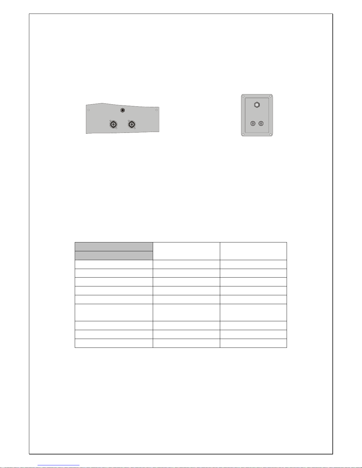
Types de connections présentes sur les enceintes en système passif.
FULL RANGE
INPUTS
+
+
+
+
INPUT
EX 200, EX 250, EX 300, EX B 600 EX MICRO 6, EX MICRO 8
SPECIFICATIONS TECHNIQUES
Modèle
Spécifications
EX MICRO 6 EX MICRO 8
Bande passante (-10dB) 80Hz-20KHz 60Hz-18KHz
Puissance 80 W 100 W
Impédance nominale 8 ohms 8 ohms
Sensibilité 91 dB 93dB
Fréquence des filtres 2,5 KHz 2,5 KHz
Efficacité acoustique
Rendement
112 dB 113 dB
Connecteurs de sortie 2 x Jack 2 x Jack
Dimensions 360 x 200 x 232 mm 410 x 230 x 280 mm
Poids Net 4,5 Kg 6 Kg
Page 4
4
Modèle
Spécifications
EX 200 et 200 A EX 250 et 250 A EX 300 et 300 A EX B 600 et EX
B 600 A
Bande passante
(-10dB)
60Hz-18KHz 45Hz-18KHz 50 Hz-18KHz 40 Hz-125Hz
Puissance 200 W 250 W 300 W 600 W
Impédance
nominale
8 ohms 8 ohms 8 ohms 4 ohms
Sensibilité 95 dB 96 dB 97dB 97 dB
Dispersion
nominale
90 °H x 60 ° V 90 °H x 60 ° V 90 °H x 60 ° V
Fréquence
des filtres
2,5 KHz 2,5 KHz 2,5 KHz
Efficacité
acoustique
Rendement
120 dB 121 dB 122 dB 126 dB
Connecteurs de
sortie
2 x speakon, 1 x
Jack
2 x speakon, 1 x
Jack
2 x speakon, 1 x
Jack
2 x speakon, 1 x
Jack
Dimensions 530 x 310 x 345 630 x 330 x 410 720 x 365x495 640x480x500
Poids Net 14 Kg 19 Kg 24 Kg 30 Kg
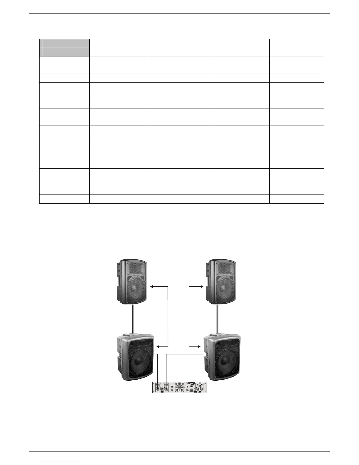
EXEMPLES DE CONNEXIONS
AVEC LE SYSTEME PASSIF
CH B
CH A
+
BRI DGE D
CH B
CH A
BRI DGE D
GND
FLO ATIN G
FU SE
FAN
T0.5 AH
OU TPU T
CH B
CH A
MAI N
T10 AH
STE RE O
BRI DGE D
CH B CH A
VOL TAG E SE LEC TOR
AC INP UT
FU SE
INP UT
+
SERIAL NO:
DO NOT OPEN
RISK OF ELECTRIC SHOCK
CAUT ION
321
+
+
F
U
S
E
+++++
+
F
U
S
E
EX 200
EX 250
EX 200
EX 250
EX B 600
EX B 600
Ampli
Page 5
5
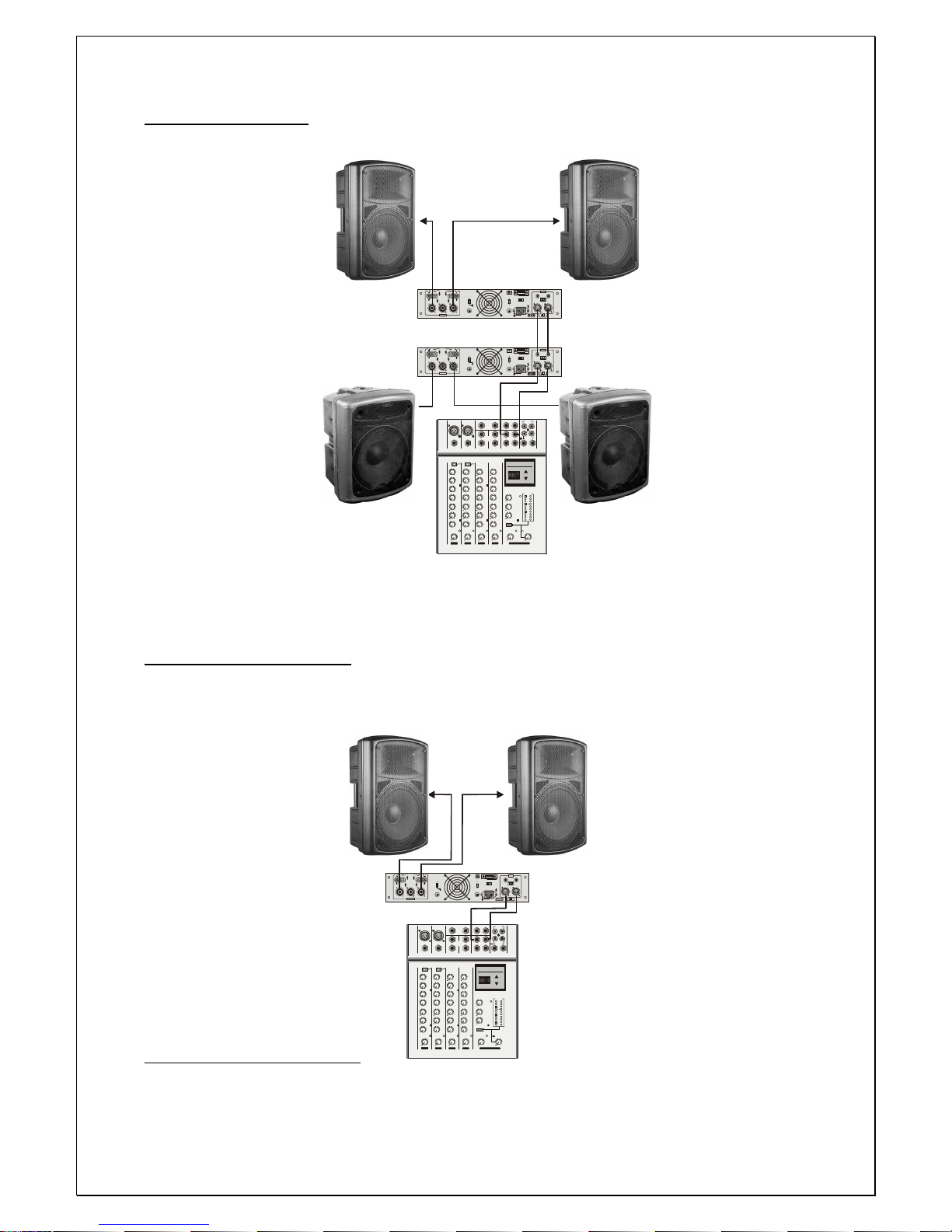
BI AMPLIFICATION
CH B CH A
+
BRI DGE D
CH B CH ABRI DGE D
GND
FLO ATIN G
FU SE
FAN
T0.5 AH
OU TPU T
CH B
CH A
MAI N
T10 AH
STE RE O
BRI DGE D
CH B CH A
VOL TAG E SE LEC TOR
AC INP UT
FU SE
INP UT
+
SERIAL NO:
DO NOT OPEN
RISK OF ELECTRIC SHOCK
CAUT ION
321
+
+
F
U
S
E
+++++
+
F
U
S
E
CH B CH A
+
BRI DGE D
CH B CH ABRI DGE D
GND
FLO ATIN G
FU SE
FAN
T0.5 AH
OU TPU T
CH B
CH A
MAI N
T10 AH
STE RE O
BRI DGE D
CH B CH A
VOL TAG E SE LEC TOR
AC INP UT
FU SE
INP UT
+
SERIAL NO:
DO NOT OPEN
RISK OF ELECTRIC SHOCK
CAUT ION
321
+
+
F
U
S
E
+++++
+
F
U
S
E
MIC MIC
LINE IN LINE IN
BAL
OR
UNBA L
BAL
OR
UNBA L
EFF R ETURN
IN
L R
21
L
L
R
R
TAPE IN
TAPE OUT
7
4
2
0
-10
-7
-4
-2
+15
-15
L
R
PEAK
PEAK
PEAK
PEAK
PEAK
LO - CUT
LO - CUT
100Hz 100 Hz
PH
METER
ROOM /PHO NES
STERE O LINE IN 5/6
EFF S END MON OUT
MAIN OUT
RL
RL
INSE RT
RL
RL
BAL I N BAL I N
TAPE
0
0
RETURN
EFF
MON
SELEC T
MAIN ROOM
MAIN OUT
TAPE
DC
dB
BAL
OR
UNBA L
-20
LOW
GAIN
HIGH
MID
MON
EFF
PAN
VOL
0
+15-15
0
-60-20
0
-60-20
0
+15-15
+15-15
0
0
0
0
0
0
RL
0
0
LOW
GAIN
HIGH
MID
MON
EFF
PAN
VOL
0
+15-15
0
+15-15
+15-15
0
0
0
0
0
0
RL
0
0
LOW
GAIN
HIGH
MID
MON
EFF
PAN
VOL
0
0
0
+15-15
0
+15-15
+15-15
0
0
0
0
0
0
RL
0
0
LOW
GAIN
HIGH
MID
MON
EFF
PAN
VOL
0
0
0
+15-15
0
+15-15
+15
-15
0
0
0
0
0
0
RL
0
0
0
0
0
0
0
0
0
0
STERE O LINE 3 /4
IN
MAIN SECTION
5/
61 23/4
PROG RAM
12 - 196m S
UP
DOW N
DIGITAL EFFECT
mS
MIC
LINE IN
BAL
OR
UNBA L
1
LO - CUT
100Hz
BAL I N
GAIN
1
EX 200
EX 250
EX B 600
Ampli
Ampli
EX 200
EX 250
EX B 600
Table de mixage
AMPLIFICATION SIMPLE
MIC MIC
LINE IN LINE IN
BAL
OR
UNBA L
BAL
OR
UNBA L
EFF R ETURN
IN
L R
21
L
L
R
R
TAPE IN
TAPE OUT
7
4
2
0
-10
-7
-4
-2
+15
-15
L
R
PEAK
PEAK
PEAK
PEAK
PEAK
LO - CUT
LO - CUT
100Hz 100 Hz
PH
METER
ROOM /PHO NES
STERE O LINE IN 5/6
EFF S END MON OUT
MAIN OUT
RL
RL
INSE RT
RL
RL
BAL I N BAL I N
TAPE
0
0
RETURN
EFF
MON
SELEC T
MAIN ROOM
MAIN OUT
TAPE
DC
dB
BAL
OR
UNBA L
-20
LOW
GAIN
HIGH
MID
MON
EFF
PAN
VOL
0
+15-15
0
-60-20
0
-60-20
0
+15-15
+15-15
0
0
0
0
0
0
RL
0
0
LOW
GAIN
HIGH
MID
MON
EFF
PAN
VOL
0
+15-15
0
+15-15
+15-15
0
0
0
0
0
0
RL
0
0
LOW
GAIN
HIGH
MID
MON
EFF
PAN
VOL
0
0
0
+15-15
0
+15-15
+15-15
0
0
0
0
0
0
RL
0
0
LOW
GAIN
HIGH
MID
MON
EFF
PAN
VOL
0
0
0
+15-15
0
+15-15
+15-15
0
0
0
0
0
0
RL
0
0
0
0
0
0
0
0
0
0
STERE O LINE 3 /4
IN
MAIN SECTION
5/
61 23/4
PROG RAM
12 - 196m S
UP
DOW N
DIGITAL EFFECT
mS
MIC
LINE IN
BAL
OR
UNBA L
1
LO - CUT
100Hz
BAL I N
GAIN
1
CH B
CH A
+
BRI DGE D
CH B
CH A
BRI DGE D
GND
FLO ATIN G
FU SE
FAN
T0.5 AH
OU TPU T
CH B
CH A
MAI N
T10 AH
STE RE O
BRI DGE D
CH B CH A
VOL TAG E SE LEC TOR
AC INPU T
FU SE
INP UT
+
SERIAL NO:
DO NOT OPEN
RISK OF ELECTRIC SHOCK
CAUT ION
321
+
+
F
U
S
E
+++++
+
F
U
S
E
EX 200
EX 250
EX 300
EX 200
EX 250
EX 300
Ampli
Table
de
mixage
Page 6
6
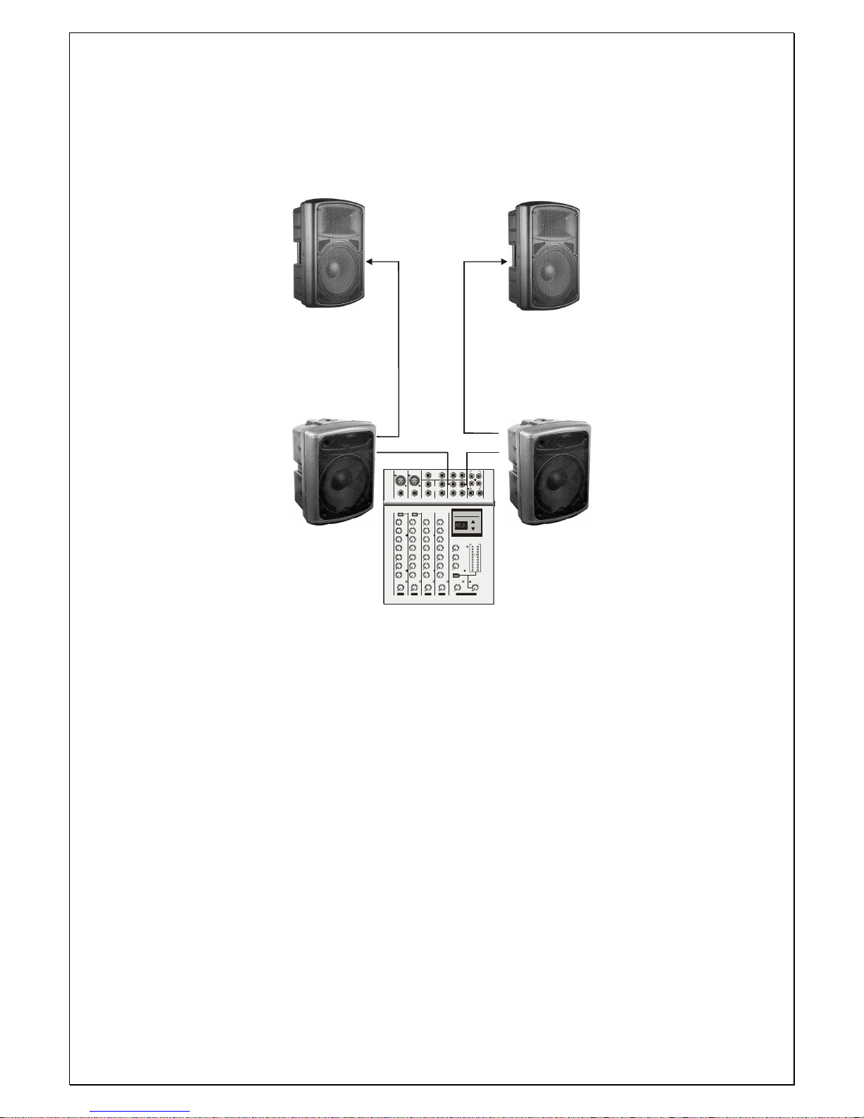
AVEC LE SYSTEME ACTIF
MIC M IC
LINE IN LIN E IN
BAL
OR
UNBA L
BAL
OR
UNBA L
EFF RET URN
IN
L R
21
L
L
R
R
TAP E IN
TAP E OUT
7
4
2
0
-10
-7
-4
-2
+15
-15
L
R
PEA K
PEA K
PEA K
PEA K
PEA K
LO - C UT
LO - C UT
100Hz 100 Hz
PH
METER
ROO M/P HON ES
STE REO LIN E IN 5/6
EFF SEN D MON O UT
MA IN OU T
RL
RL
INSE RT
RL
RL
BAL IN BA L IN
TAP E
0
0
RET URN
EFF
MO N
SEL ECT
MA IN RO OM
MA IN OUT
TAP E
DC
dB
BAL
OR
UNBA L
-20
LOW
GAIN
HIGH
MID
MO N
EFF
PAN
VOL
0
+15-15
0
-60-20
0
-60-20
0
+15-15
+15-15
0
0
0
0
0
0
RL
0
0
LOW
GAIN
HIGH
MID
MO N
EFF
PAN
VOL
0
+15-15
0
+15-15
+15-15
0
0
0
0
0
0
RL
0
0
LOW
GAIN
HIGH
MID
MO N
EFF
PAN
VOL
0
0
0
+15-15
0
+15-15
+15-15
0
0
0
0
0
0
RL
0
0
LOW
GAIN
HIGH
MID
MO N
EFF
PAN
VOL
0
0
0
+15-15
0
+15-15
+15
-15
0
0
0
0
0
0
RL
0
0
0
0
0
0
0
0
0
0
STE REO LIN E 3/ 4
IN
MAIN S ECTION
5/
61 23/4
PROG RAM
12 - 196 mS
UP
DOW N
DIGITAL EFFECT
mS
MIC
LINE IN
BAL
OR
UNBA L
1
LO - C UT
100Hz
BAL IN
GAIN
1
EX 200-A
EX 250-A
EX B 600-A
EX 200-A
EX 250-A
EX B 600-A
Table de mixage
Page 7
7
USER MANUAL
PROFESSIONNAL SPEAKERS
EX SERIES
Page 8

8
SAFETY INSTRUCTIONS
Do not remove the front metal grille which protects the loudspeaker; avoid touching if
with any serviceable parts to prevent any irreparable damage
Do not use solvents such as acetone or alcohol to clean the system,as they would
damage its finish.
Avoid exposing the system to the action of atmospheric agents for a long time
(dampness, excessive heat, strong temperature variations, etc.)
Clean the system once in a while to avoid excessive dust; when possible protect the
system inside its original packaging for any transport purpose
Suspending this system should be done by qualified persons following safe rigging
standards.
WARNING
Never plug in jacks with signal running into the speaker or cable.
FEATURES
Enclosure adopted a high impact polymer, injection molded shaping. It has high intensity
and light weight, set a handle, easy to carry it. Designed non-symmetrical enclosure
outline. It can be used for fold-back speaker.
Woofer speaker make a high powered pro-speaker. It has wide-range, low distortion,
high sensitivity, adopted a aluminium frame. It has non-mechanical resonance.
Driver selected a titanium diaphragm, and light mass voice coil, make it high frequency
reached 18,000Hz.
Crossover adopted a high quality polypropylene condenser, flame proof resistor, low less
inductance. Precision design dividing frequency and smooth frequency response, and
designed auto-limit protection circuit to avoid damage driver.
Page 9
9
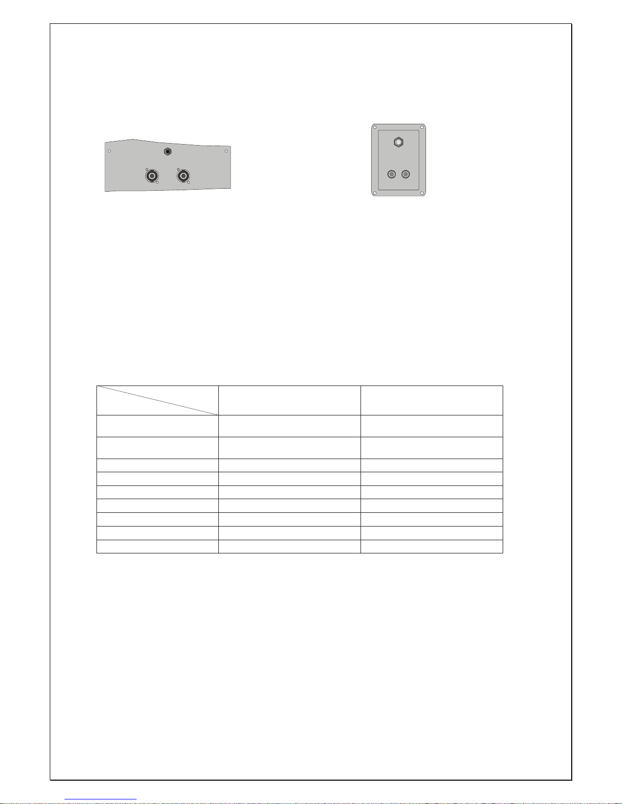
CONNECTION
Run signal into the link inputs XLR connectors.
FULL RANGE
INPUTS
+
+
+
+
INPUT
EX 200, EX 250, EX 300, EX B 600 EX MICRO 6, EX MICRO 8
TECHNICAL SPECIFICATIONS
TECHICAL SPECIFICATIONS
Speci ficat ions
Frequency Range
(-10dB)
Power Capacity
(Continous Pink Nois e)
Nomin al Impedance
Sensitivity (1W@ 1m)
Crossover Freque ncy
Maximum SPL
Input Connectors
Dimensions (H W D)
× ×
Net Weight
EX MICR06
80Hz-20 KH z
80W
8 ohms
91dB
2.5KH z
112dB
360 200 232 mm
× ×
4.5 kg
EX MICR08
60Hz-18KHz
100W
8 ohms
93dB
2.5KH z
113dB
Bin ding post-1 Jack
×
410 23 0 2 80 mm
× ×
6 kg
Bin ding post-1 Jack
×
Model
Page 10
10
Speci ficat ions
Frequency Range
(-10dB)
Power Capacity
(Continous Pink Nois e)
Nomin al Impedance
Sensitivity (1W@ 1m )
Nomin al Dis persion
Crossover Freque ncy
Maximum SPL
Input Connectors
Dimensions (H W D)
× ×
Net Weight
EX 200
60Hz- 18KHz
200W
8 ohms
95dB
90 H x 60 V
2.5KH z
120 dB
2 Speakon-1 Jack
× ×
530 310 3 45 mm
× ×
14 kg
EX 250
45Hz-18KHz
250W
8 ohms
96dB
90 H x 60 V
2.5KH z
121dB
630 330 410 m m
× ×
19 kg
EX B60 0-A
40Hz-125Hz
600W
4 ohms
97dB
126dB
640 480 500 mm
× ×
30 kg
EX B60 0
40Hz-18KHz
300W
8 ohms
97dB
90 H x 60 V
2.5KH z
122dB
720 365 495 mm
× ×
24 kg
2 Speakon-1 Jack
× ×
2 Speakon-1 Jack
× ×
2 Speakon-1 Jack
× ×
Model
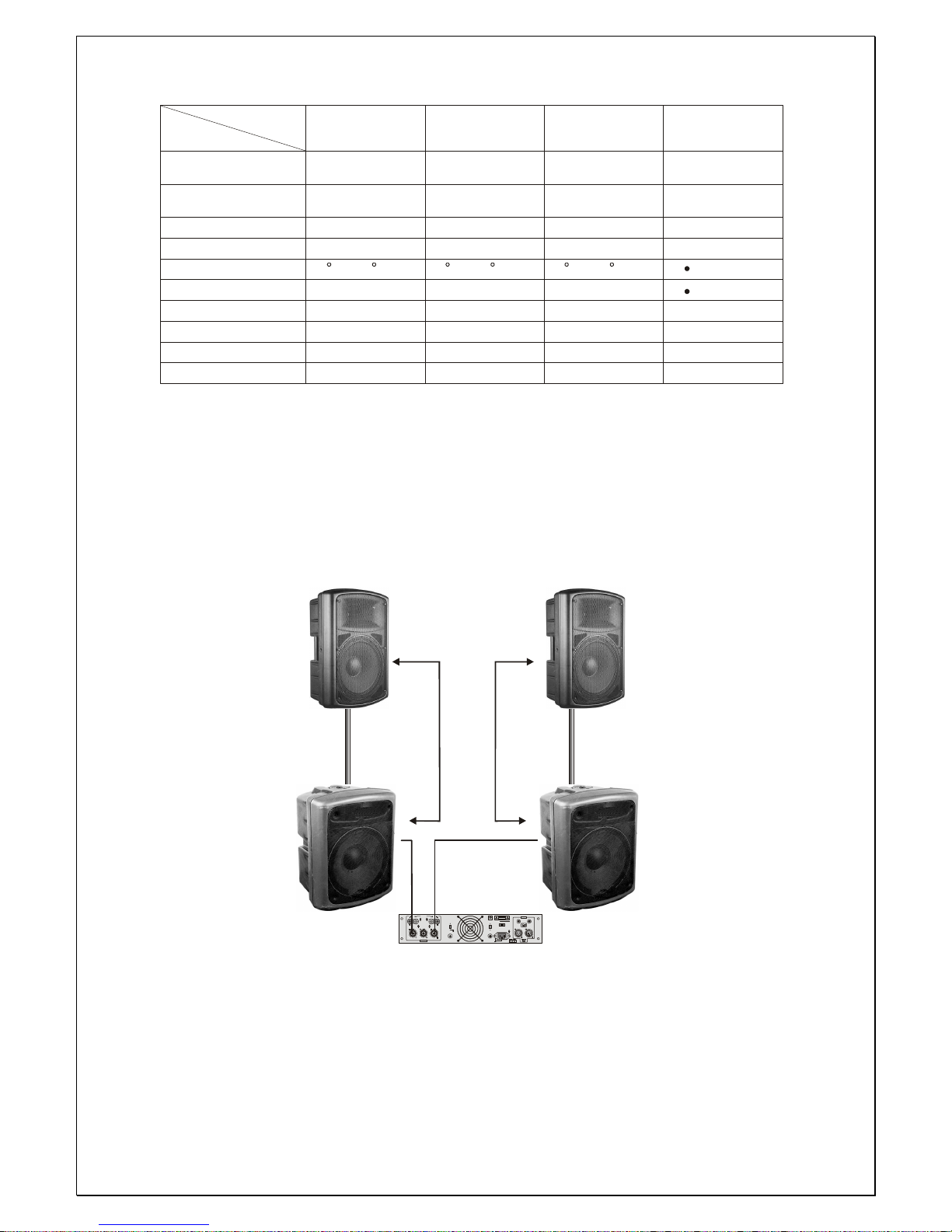
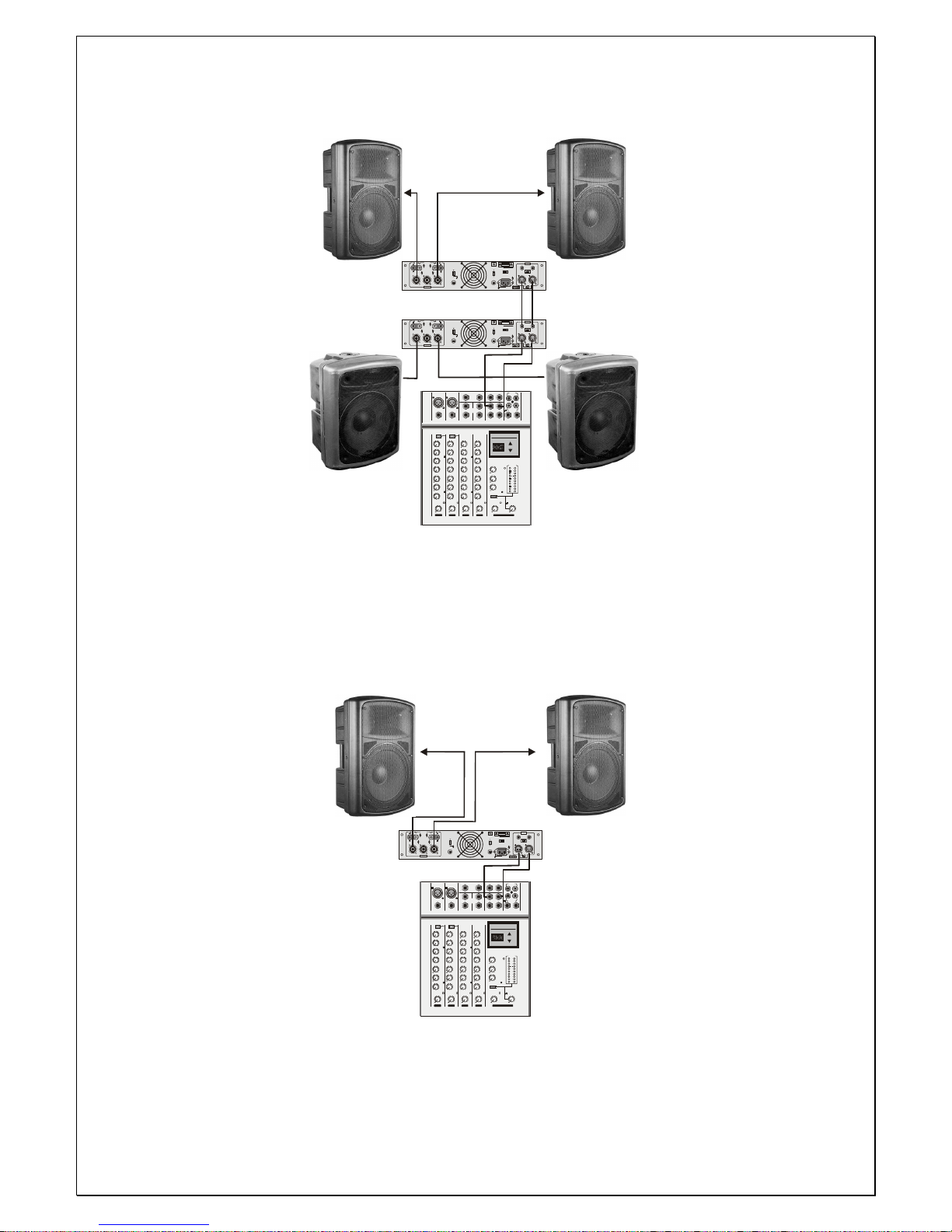
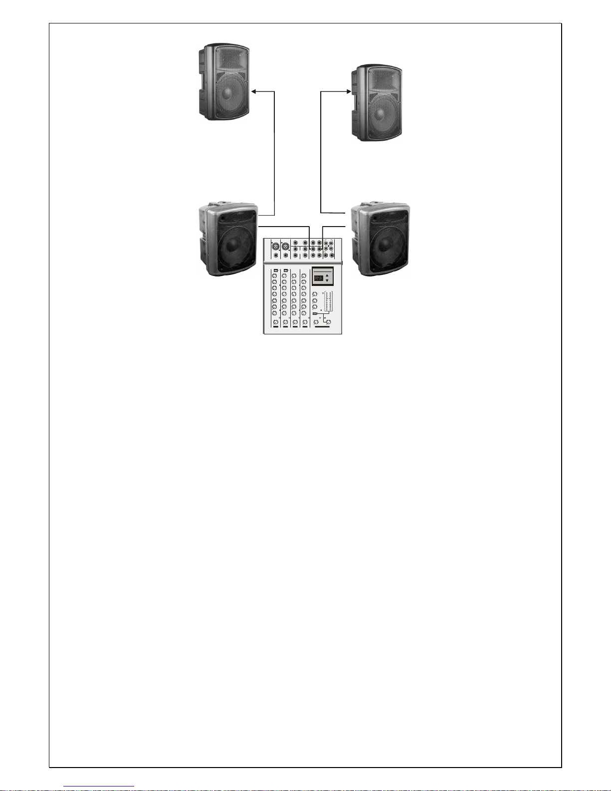
CONNECTION EXAMPLES
CH B
CH A
+
BRI DGE D
CH B
CH A
BRI DGE D
GND
FLO ATIN G
FU SE
FAN
T0.5 AH
OU TPU T
CH B
CH A
MAI N
T10 AH
STE RE O
BRI DGE D
CH B CH A
VOL TAG E SE LEC TOR
AC INPU T
FU SE
INP UT
+
SERIAL NO:
DO NOT OPEN
RISK OF ELECTRIC SHOCK
CAUT ION
321
+
+
F
U
S
E
+++++
+
F
U
S
E
EX 200
EX 250
EX 200
EX 250
EX B 600
EX B 600
Ampli
Page 11
11
CH B CH A
+
BRI DGE D
CH B CH ABRI DGE D
GND
FLO ATIN G
FU SE
FAN
T0.5 AH
OU TPU T
CH B
CH A
MAI N
T10 AH
STE RE O
BRI DGE D
CH B CH A
VOL TAG E SE LEC TOR
AC INPU T
FU SE
INP UT
+
SERIAL NO:
DO NOT OPEN
RISK OF ELECTRIC SHOCK
CAUT ION
321
+
+
F
U
S
E
+++++
+
F
U
S
E
CH B CH A
+
BRI DGE D
CH B CH ABRI DGE D
GND
FLO ATIN G
FU SE
FAN
T0.5 AH
OU TPU T
CH B
CH A
MAI N
T10 AH
STE RE O
BRI DGE D
CH B CH A
VOL TAG E SE LEC TOR
AC INPU T
FU SE
INP UT
+
SERIAL NO:
DO NOT OPEN
RISK OF ELECTRIC SHOCK
CAUT ION
321
+
+
F
U
S
E
+++++
+
F
U
S
E
MIC MIC
LINE IN LINE IN
BAL
OR
UNBA L
BAL
OR
UNBA L
EFF R ETURN
IN
L R
21
L
L
R
R
TAPE IN
TAPE OUT
7
4
2
0
-10
-7
-4
-2
+15
-15
L
R
PEAK
PEAK
PEAK
PEAK
PEAK
LO - CUT
LO - CUT
100Hz 100 Hz
PH
METER
ROOM /PHO NES
STERE O LINE IN 5/6
EFF S END
MON OUT
MAIN OUT
RL
RL
INSE RT
RL
RL
BAL I N BAL I N
TAPE
0
0
RETURN
EFF
MON
SELEC T
MAIN ROOM
MAIN OUT
TAPE
DC
dB
BAL
OR
UNBA L
-20
LOW
GAIN
HIGH
MID
MON
EFF
PAN
VOL
0
+15-15
0
-60-20
0
-60-20
0
+15-15
+15-15
0
0
0
0
0
0
RL
0
0
LOW
GAIN
HIGH
MID
MON
EFF
PAN
VOL
0
+15-15
0
+15-15
+15-15
0
0
0
0
0
0
RL
0
0
LOW
GAIN
HIGH
MID
MON
EFF
PAN
VOL
0
0
0
+15-15
0
+15-15
+15-15
0
0
0
0
0
0
RL
0
0
LOW
GAIN
HIGH
MID
MON
EFF
PAN
VOL
0
0
0
+15- 15
0
+15- 15
+15
-15
0
0
0
0
0
0
RL
0
0
0
0
0
0
0
0
0
0
STERE O LINE 3 /4
IN
MAIN SECTION
5/
61 23/4
PROG RAM
12 - 196m S
UP
DOW N
DIGITAL EFFECT
mS
MIC
LINE IN
BAL
OR
UNBA L
1
LO - CUT
100Hz
BAL I N
GAIN
1
EX 200
EX 250
EX B 600
Ampli
Ampli
EX 200
EX 250
EX B 600
Mixer
MIC MIC
LINE IN LINE IN
BAL
OR
UNBA L
BAL
OR
UNBA L
EFF R ETURN
IN
L R
21
L
L
R
R
TAPE IN
TAPE OUT
7
4
2
0
-10
-7
-4
-2
+15
-15
L
R
PEAK
PEAK
PEAK
PEAK
PEAK
LO - CUT
LO - CUT
100Hz 100 Hz
PH
METER
ROOM /PHO NES
STERE O LINE IN 5/6
EFF S END M ON OUT
MAIN OUT
RL
RL
INSE RT
RL
RL
BAL I N BAL I N
TAPE
0
0
RETURN
EFF
MON
SELEC T
MAIN R OOM
MAIN OUT
TAPE
DC
dB
BAL
OR
UNBA L
-20
LOW
GAIN
HIGH
MID
MON
EFF
PAN
VOL
0
+15-15
0
-60-20
0
-60-20
0
+15-15
+15-15
0
0
0
0
0
0
RL
0
0
LOW
GAIN
HIGH
MID
MON
EFF
PAN
VOL
0
+15-15
0
+15-15
+15-15
0
0
0
0
0
0
RL
0
0
LOW
GAIN
HIGH
MID
MON
EFF
PAN
VOL
0
0
0
+15-15
0
+15-15
+15-15
0
0
0
0
0
0
RL
0
0
LOW
GAIN
HIGH
MID
MON
EFF
PAN
VOL
0
0
0
+15-15
0
+15-15
+15-15
0
0
0
0
0
0
RL
0
0
0
0
0
0
0
0
0
0
STERE O LINE 3 /4
IN
MAIN SECTION
5/
61 23/4
PROG RAM
12 - 196m S
UP
DOW N
DIGITAL EFFECT
mS
MIC
LINE IN
BAL
OR
UNBA L
1
LO - CUT
100Hz
BAL I N
GAIN
1
CH B
CH A
+
BRI DGE D
CH B
CH A
BRI DGE D
GND
FLO ATIN G
FU SE
FAN
T0.5 AH
OU TPU T
CH B
CH A
MAI N
T10 AH
STE RE O
BRI DGE D
CH B CH A
VOL TAG E S ELEC TOR
AC INPU T
FU SE
INP UT
+
SERIAL NO:
DO NOT OPEN
RISK OF ELECTRIC SHOCK
CAUT ION
321
+
+
F
U
S
E
+++++
+
F
U
S
E
EX 200
EX 250
EX 300
EX 200
EX 250
EX 300
Ampli
Mixer
Page 12
12
MIC M IC
LINE IN LINE IN
BAL
OR
UNBA L
BAL
OR
UNBA L
EFF RET URN
IN
L R
21
L
L
R
R
TAP E IN
TAP E OUT
7
4
2
0
-10
-7
-4
-2
+15
-15
L
R
PEA K
PEA K
PEA K
PEA K
PEA K
LO - C UT
LO - C UT
100Hz 100 Hz
PH
METER
ROO M/P HON ES
STE REO LIN E IN 5/6
EFF SEN D M ON O UT
MA IN OU T
RL
RL
INSE RT
RL
RL
BAL IN BA L IN
TAP E
0
0
RET URN
EFF
MO N
SEL ECT
MA IN RO OM
MA IN OUT
TAP E
DC
dB
BAL
OR
UNBA L
-20
LOW
GAIN
HIGH
MID
MO N
EFF
PAN
VOL
0
+15-15
0
-60-2 0
0
-60-2 0
0
+15-15
+15-15
0
0
0
0
0
0
RL
0
0
LOW
GAIN
HIGH
MID
MO N
EFF
PAN
VOL
0
+15-15
0
+15-15
+15-15
0
0
0
0
0
0
RL
0
0
LOW
GAIN
HIGH
MID
MO N
EFF
PAN
VOL
0
0
0
+15-15
0
+15-15
+15-15
0
0
0
0
0
0
RL
0
0
LOW
GAIN
HIGH
MID
MO N
EFF
PAN
VOL
0
0
0
+15-15
0
+15-15
+15
-15
0
0
0
0
0
0
RL
0
0
0
0
0
0
0
0
0
0
STE REO LIN E 3/ 4
IN
MAIN S ECTION
5/
61 23/4
PROG RAM
12 - 196 mS
UP
DOW N
DIGITAL EFFECT
mS
MIC
LINE IN
BAL
OR
UNBA L
1
LO - C UT
100Hz
BAL IN
GAIN
1
EX 200-A
EX 250-A
EX B 600-A
EX 200-A
EX 250-A
EX B 600-A
Mixer
Page 13
13
NOTICE D’UTILISATION
ENCEINTES
SERIES EX
SYSTEME ACTIF
Page 14

14
INSTRUCTIONS DE SECURITE
• Ne pas enlever la grille métallique avant qui protège l’enceinte.
• Ne pas utiliser de solvants tels que l’acétone ou l’alcool pour nettoyer l’appareil,
cela pourrait entraîner des dommages.
• Ne pas exposer l’appareil à de trop fortes chaleurs ou variations de
températures, et à l’humidité.
• Nettoyer l’appareil de façon régulière afin d’éviter un dépôt de poussière
excessif. Afin de le protéger, il est préférable de le transporter dans son
emballage d’origine.
• La suspension de cet appareil doit être réalisée par un personnel qualifié, à
l’aide d’un mécanisme de câblage sécurisé.
• Ne jamais connecter les Jacks sans avoir préalablement éteint l’appareil.
CARACTERISTIQUES
• Les enceintes sont moulées dans un polymère de haute qualité. Elles sont d’une
grande puissance, légères, pourvues d’une poignée facilitant le transport.
Conception de caisse non symétrique, peut être utilisée en retour de scène.
• Les haut-parleurs des enceintes ont une puissance élevée. Ils ont une portée très
large, de basses distorsions, une très haute sensibilité, et sont entourés d’un
cadre en aluminium, qui ne procure aucune résonance mécanique.
• Les techniciens ont sélectionné une membrane en titane, et une bobine légère qui
lui permette d’atteindre une haute fréquence de 18 000 Hz.
• Les filtres sont dotés de condensateurs poly-propylènes de haute qualité, de
résistances ininflammables de faible inductance.
• Séparation précise des fréquences, réponse en fréquence lissée, circuit de
protection d’autolimitation pour éviter d’endommager l’appareil.
Page 15
15
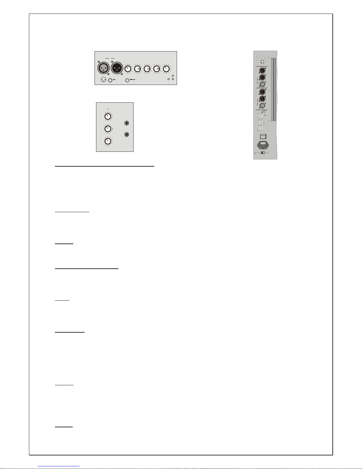
CONTROLES
EX-200A, EX-250, EX-300A
1
0
-20
-1
5
-15
-
1
2
0
+
1
5
+
1
5
+
12
1
0
6
0
mi
c
3
0
l
in
e
GA
I
N
HI
G
H
M
I
D
LOW
VO
L
HF
LF
AASSP WR
LINE MI CGND L IFT
12
XLR
3
XLR
1-Gnd
2-Hot
3-Cold
IN
L
I
N
K
OU
T
0
0
0
0
0
10
0
1
0
0
10
IN
P
U
T
A
U
X
O
U
T
POWER
G
A
I
N
V
O
L
U
M
E
T
O
N
E
EX MICRO , EX MICRO 8
VOL
HP
FILTERED
OUT
HP
FILTERED
OUT
OUT
OUT
LINK
LINK
IN
IN
PWR
GND
LIFT
POWER
FUSE T-5A
115V/230V
R
L
AASS
+
+
0
10
EX B 600A
LIAISON ENTREE IN / SORTIE OUT :
Les prises XLR IN et OUT sont symétriques. La prise XLR IN
Permet la connexion d’un micro ou d’un signal audio tel qu’une
Sortie de table de mixage. La prise XLR OUT connectée en
Parallèle avec la prise XLR IN permet de multiples connexions
De système avec le même signal.
LINE / MIC :
Appuyer sur le bouton LINE / MIC pour sélectionner soit la position MIC si un micro ou un appareil de faible
niveau (guitare électrique…) est connecté, soit la position LINE qui permet la connexion de sources telles
que : table de mixage, lecteur CD…
GAIN :
Règle le niveau du signal d’entrée IN, assurant un fonctionnement parfait des circuits des canaux. Pour un
ajustement bien équilibré, régler le volume au ¾ puis ajuster le GAIN de la même façon.
HIGH / MEDIUM / LOW:
Equaliseur 3 bandes pour corriger le son. Ces réglages sont placés après le GAIN, et s’ils sont trop au
maximum, ils peuvent saturer la voie. Dans ce cas, ajuster les contrôles de manière à réduire la saturation.
Quand les potentiomètres sont réglés à « 0 », la tonalité reste inchangée.
VOL :
Potentiomètre VOL pour contrôler le niveau du signal du canal. La performance optimale du circuit du signal
est atteinte lorsque le bouton est positionné au ¾ dans le sens des aiguilles d’une montre, et le contrôle des
gains réglé sur le niveau désiré.
GND LIFT :
Il existe deux positions afin de séparer le signal masse source de celui de l’appareil.
ON : Le signal masse source est déconnecté de celui de l’appareil. Si un bourdonnement est entendu dans les
haut-parleurs, la position ON rompt le circuit de la masse, ce qui est souvent la cause de cette
interférence.
OFF : Le signal masse source est connecté à la masse de l’appareil.
N’UTILISER LA MASSE QU’AVEC DES SIGNAUX SYMETRIQUES.
AASS :
Circuit processeur qui protège les composants des tensions excessives. Quand le signal audio atteint un seuil
dangereux pour les composants, le système AASS réduit le signal de sortie. Le temps de réaction du
système est très rapide. Ces systèmes d’enceintes sont caractérisés par deux systèmes de protection
séparés, l’un pour les basses fréquences, et l’autre pour les hautes fréquences. Ces protections se
visualisent grâce aux LED HF et LF éclairées sur la face de contrôle.
PWR :
Une LED indique la mise en route du système.
Page 16
16
CONNECTIONS
Connection side
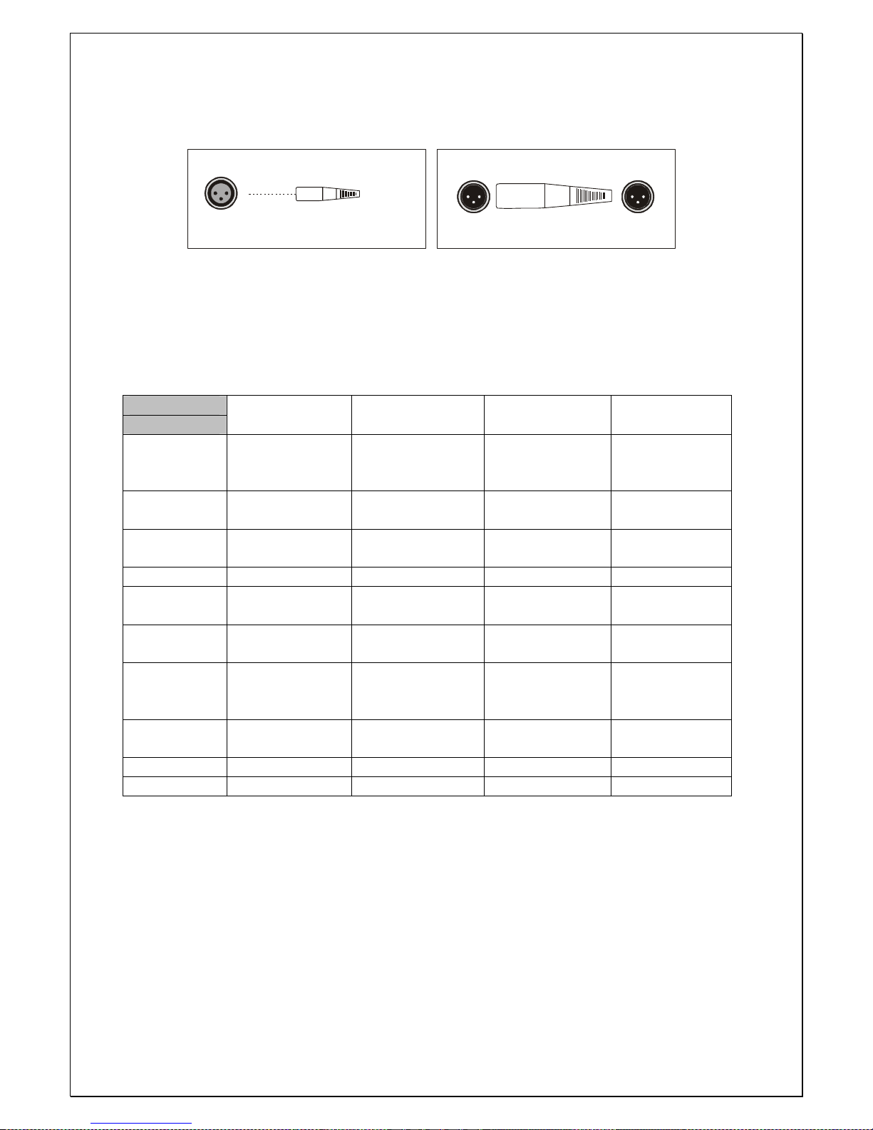
1. Masse(Shield) 2. Phase + (Hot) 3. Phase - (Cold)
Wirings side
XLR/OUT
132
231
XLR-F
1=SHIELD
2=HOT
3=COLD
132
XLR/IN
EX-200A , EX-250A, EX-300A, et EX B 600A
SPECIFICATIONS TECHNIQUES
Modèle
Spécifications
EX 200 A EX 250 A EX 300 A EX B 600 A
Bande
passante
(-10dB)
60Hz-18KHz 45Hz-18KHz 50 Hz-18KHz 40 Hz-125Hz
Puissance
RMS
200 W 250 W 300 W 600 W
Impédance
nominale
8 ohms 8 ohms 8 ohms 8 ohms
Sensibilité 95 dB 96 dB 97dB 97 dB
Dispersion
nominale
90 °H x 60 ° V 90 °H x 60 ° V 90 °H x 60 ° V
Fréquence
des filtres
2,5 KHz 2,5 KHz 2,5 KHz
Efficacité
acoustique
Rendement
120 dB 121 dB 122 dB 126 dB
Connecteurs
de sortie
XLR XLR XLR XLR
Dimensions 530 x 310 x 345 630 x 330 x 410 720 x 365x495 640x480x500
Poids Net 18,5 Kg 23,5 Kg 28,5 Kg 35 Kg
Page 17
17
EXEMPLES DE
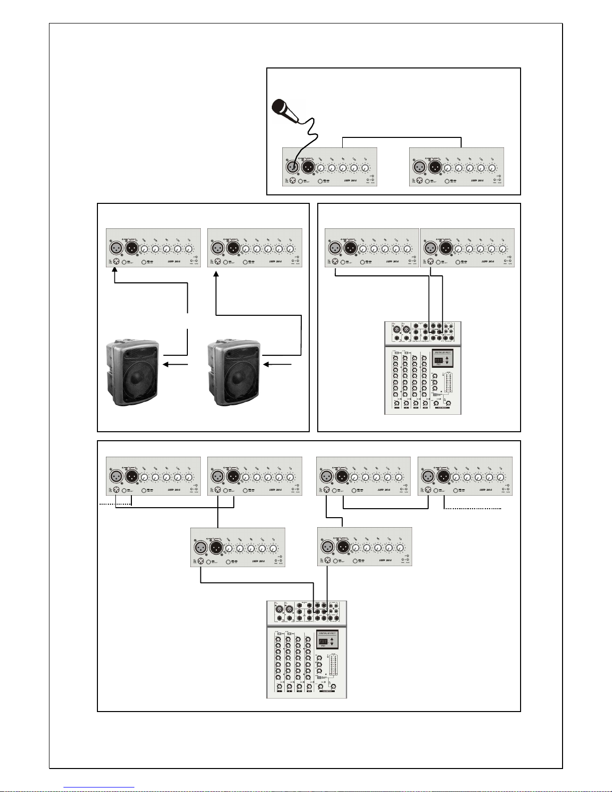
Connexion d’un microphone et de deux EX-200 en mode
CONNECTIONS
parallèle, Ne pas approcher le microphone
SUGGERES
des haut-parleurs (Larsen)
EX-200A,EX-250A, EX-300A
EX-200A,EX-250A EX-200A,EX-250A EX-200A,EX-250A, EX-300A
Configuration basique
Les sorties Master L/R
De la table de mixage
Sont connectèes à Sortie
Non Filtrè ou L’entrèe IN des Principale L R
EX B 600A
Filtrè
EX B 600A
Non Filtrè Enceintes
ou Filtrè
D’ une table D’ une table
De mixage De mixage
Configuration de 2 enceintes et caissons de basse
Branchès à travers une sartie filtrèe ou non filtrèe Table de mixage
EX-200A,EX-250A, EX-300A
OUT OUT
IN IN
Sortie principale L R
Configuration de plusieurs enceintes
Par la sortie XLR OUT, en parallèle
Avec l’entrèe XLR IN
Table de mixage
Page 18
18
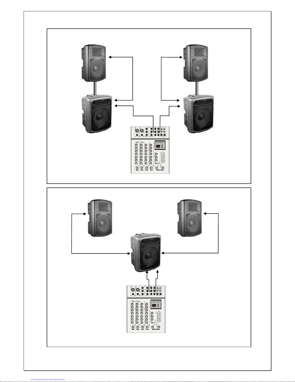
EX-200A,EX-250A EX-200A,EX-250A
EX B 600A EX B 600A
Connexion de 2 EX B 600A avec sortie filtrèe et 2 satellites
EX-200A, EX-250A EX-200A, EX-250A
EX B 600A
Connexion de 1 EX B 600A avec sortie filtrèe et 2 satellites
Page 19
19
USER MANUAL
SOUND BOXES
ACTIVE SYSTEM
Page 20

20
SAFETY INSTRUCTIONS
• Before powering the speaker system, make sure that the mains power voltage
is not higher than that shown on the rear panel.
• Never use the appliance if the power cable or plug are not in perfect
conditions, avoid excessive bending, pulling or cutting of the power cable.
• To prevent the risk of electric shock, never remove cover (or back) of the
speaker system.
• Do not use solvents such as acetone or alcohol to clean the system, as they
would damage its finish.
• Avoid exposing the system to the action of atmospheric agents for a long time
(dampness, excessive heat, strong temperature variations, etc.)
• Clean the system once in a while to avoid excessive dust, when possible protect
the system inside its original packaging for any transport purpose.
WARNING
• To avoid any annoying feedback or noise (larsen effect), make sure that the
microphone cables are screened and that microphones are never pointed in the
direction of the loudspeakers.
CARACTERISTIQUES
• Enclosure adopted a high impact polymer, injection molded shaping. It has high
intensity and light weight, set a handle easy to carry it. Designed non-symetrical
enclosure outline. It can be used for a fold-back speaker.
• Woofer speaker make a high powered pro-speaker. It has wide-range, low
distorsion, high sensitivity, adopted an aluminium frame. It has non-mechanical
resonance.
• Driver selected a titanium diaphragm, and light mass voice coil, make it high
frequency reached 18,000 Hz.
• The new A.A.S.S (automatic amplitude servo system) processor ensures total
protection of the transducers and improvement of the acoustic response.
Page 21
21
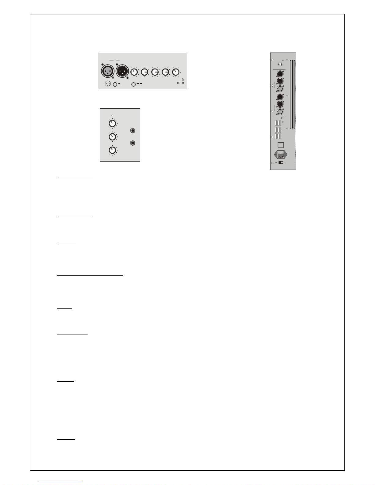
CONTROLS
EX-200A, EX-250, EX-300A
1
0
-20
-1
5
-15
-
12
0
+
15
+1
5
+
12
1
0
6
0
m
i
c
3
0
l
in
e
GAI
N
H
I
G
H
M
I
D
LOW
VO
L
HF
LF
AASSPWR
LINE M ICGND L IFT
12
XLR
3
XLR
1-Gnd
2-Hot
3-Cold
IN
L
I
N
K
O
U
T
0
0
0
0
0
10
0
1
0
0
10
IN
PUT
AU
X
O
U
T
POWER
G
A
I
N
V
O
L
U
M
E
T
O
N
E
EX MICRO , EX MICRO 8
VOL
HP
FILTERED
OUT
HP
FILTERED
OUT
OUT
OUT
LINK
LINK
IN
IN
PWR
GND
LIFT
POWER
FUSE T-5A
115V/230V
R
L
AASS
+
+
0
10
EX B 600A
IN link OUT :
Input and output sockets, electonically balanced. The IN XLR socket allows connection of a dynamic
microphone at low impedance or of a pre-amplified signal such as a mixer line out, the OUT socket is
connected in parallel (link) with the input IN allowing multiple connections of more systems with the same
signal.
LINE / MIC :
Switch to select either MIC position if a microphone or a low frequency appliance is connected of high level
signal sources.
GAIN :
Regulates pre-amplification of the signal coming from the input IN, ensuring perfect operation of the
channel circuits. For a well-balanced again adjustment, set the Volume to approx ¾ clockwise, then adjust
the gain accordingly.
HIGH / MEDIUM / LOW:
3-band equalization to modify the sound tone. These controls are electronically post-gain and if boosted
can clip the channel: in this case adjust the gain control anticlockwise. When the potentiometers are set to
“0”, the tone remain unchanged.
VOL :
Volume potentiometer to control the channel signal level. Normally optimal channel circuit performance is
achieved with the knob positioned at approx. ¾ clockwise and the gain control set to the desired level.
GND LIFT :
2 position selector for separating the signal source ground and the amplifier ground circuits.
ON: The signal ground is electrically disconnected from the amplifier ground circuit (the chassis). If hum is
heard in the loudspeakers, the ON position breaks the ground loop, often the cause of this interference.
OFF: The ground of the input signals is electrically connected to the amplifier ground circuit (the chassis).
USE GROUND LIFT ONLY WITH BALANCED SIGNALS.
AASS:
Processor circuit which protects the transducers from excessive tensions, when the audio signal reaches
the dangerous threshold for the transducers, the A.A.S.S system automatically intervenes by reducing the
amount of signal within acceptable limits: the time reaction of the system is very fast. The speaker system
features two separate protection systems, both for the low frequency and the high frequency drivers, the
activation of these protections is recognisable through the “HF” and “LF” leds lighting up in the control
panel.
PWR :
Led signal to indicate the switching on of the system.
Page 22
22
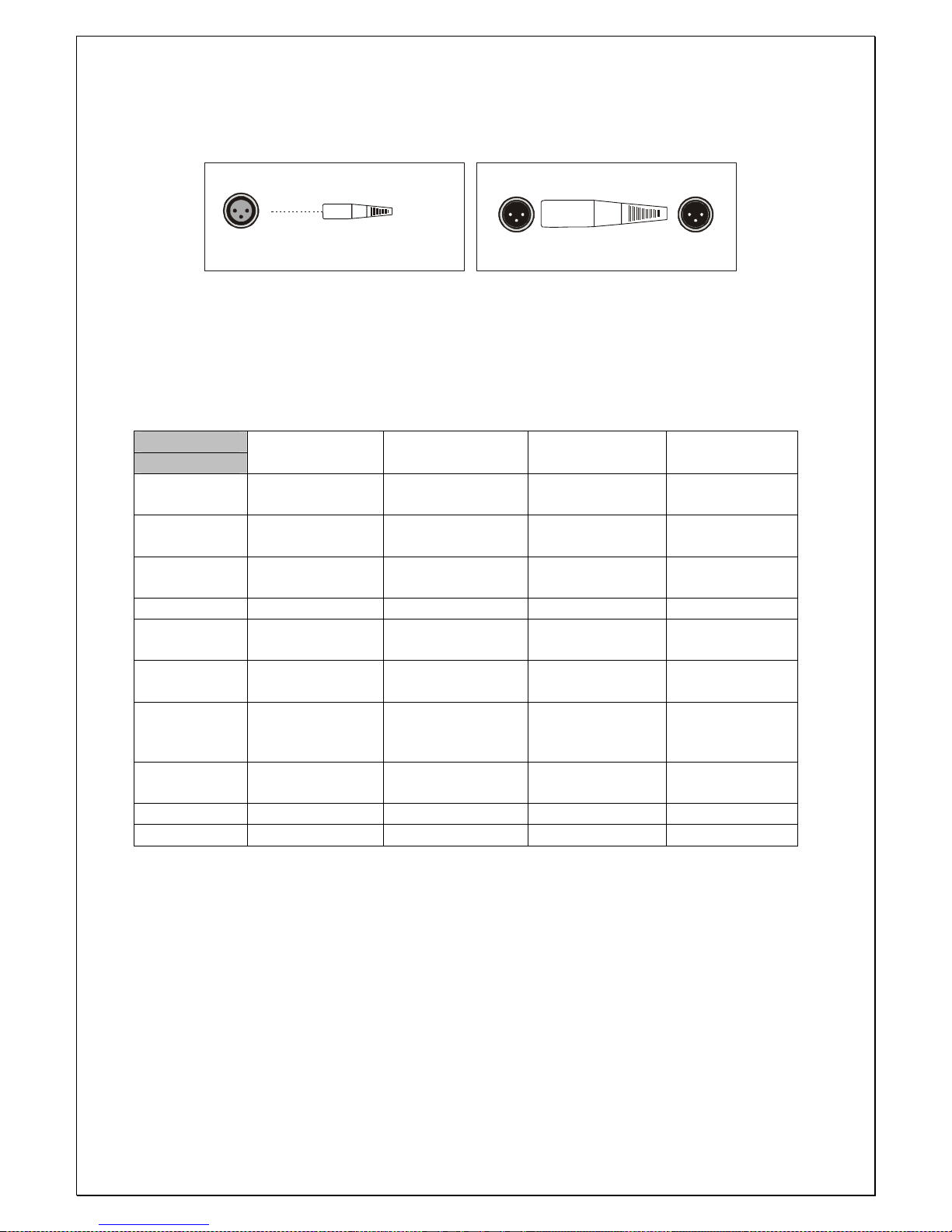
CONNECTIONS
Connection side
1. Masse(Shield) 2. Phase + (Hot) 3. Phase - (Cold)
Wirings side
XLR/OUT
132
231
XLR-F
1=SHIELD
2=HOT
3=COLD
132
XLR/IN
EX-200A , EX-250A, EX-300A, et EX B 600A
TECHNICAL SPECIFICATIONS
Model
Specifications
EX 200 A EX 250 A EX 300 A EX B 600 A
Frequency
range (-10dB)
60Hz-18KHz 45Hz-18KHz 50 Hz-18KHz 40 Hz-125Hz
Power
capacity
200 W 250 W 300 W 600 W
Nominal
impedance
8 ohms 8 ohms 8 ohms 8 ohms
Sensitivity 95 dB 96 dB 97dB 97 dB
Nominal
dispersion
90 °H x 60 ° V 90 °H x 60 ° V 90 °H x 60 ° V
Crossover
frequency
2,5 KHz 2,5 KHz 2,5 KHz
Maximum SPL 120 dB 121 dB 122 dB 126 dB
Input
connectors
XLR XLR XLR XLR
Dimensions 530 x 310 x 345 630 x 330 x 410 720 x 365x495 640x480x500
Net weight 18,5 Kg 23,5 Kg 28,5 Kg 35 Kg
Page 23
23
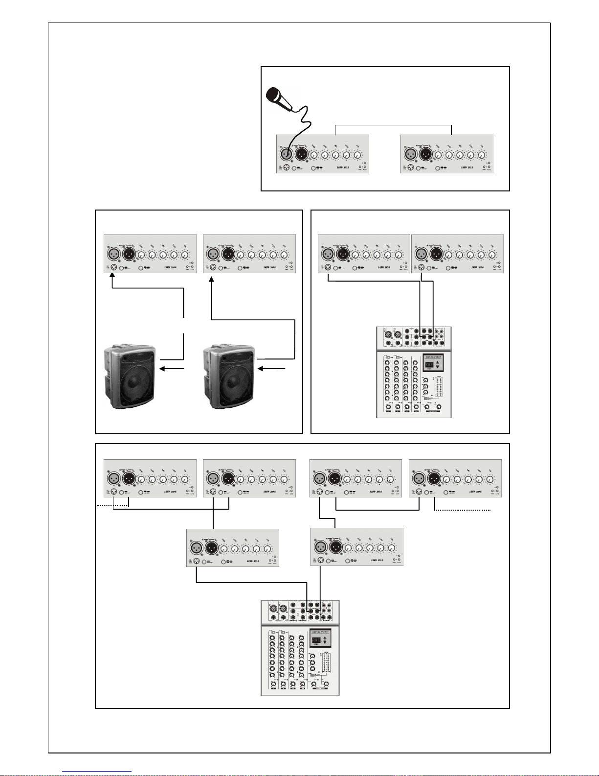
Connection of 1 microphone and of 2 EX-200 in parallel mode
CONNECTIONS
Do not point the microphone to the loudspeaker
EXAMPLES
(Larsen effect)
EX-200A,EX-250A, EX-300A
EX-200A,EX-250A EX-200A,EX-250A EX-200A,EX-250A, EX-300A
Basic configuration
The master L/R outputs
Of the mixer are connected
To the XLR IN socket
Filtered or
of the 2 EX-200 Main OUT L R
EX B 600A
not filtered
EX B 600A
Filtered
Or not filtered
Mixer Mixer
Subwoofer Subwoofer
Configuration of 2 EX-200 and subwoofers
powered through a filtered output Mixer
EX-200A,EX-250A, EX-300A
OUT OUT
IN IN
Main OUT L R
Configuration of multiple 2 EX-200
Through the XLR output socket
OUT in parallel with the XLR IN socket
Mixer
Page 24
24
EX-200A,EX-250A EX-200A,EX-250A
EX B 600A EX B 600A
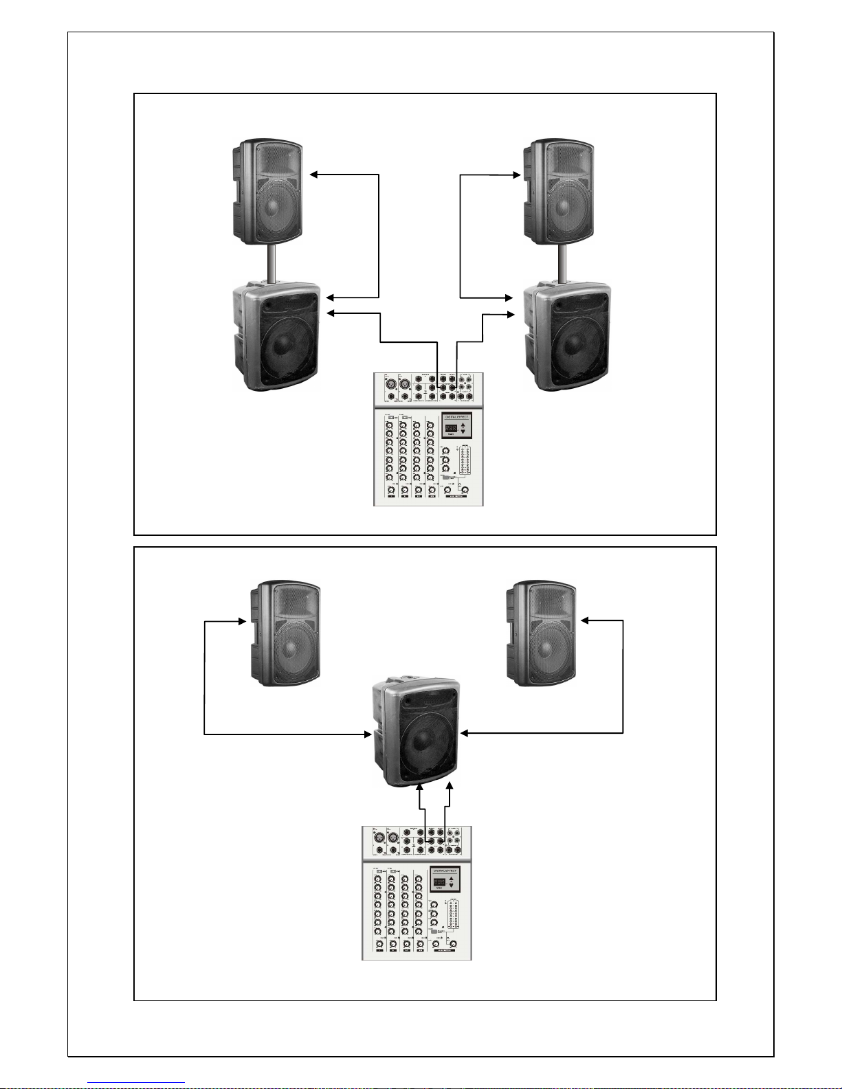
Connection of 2 EX B 600 A with filtered output and 2 satellites
EX-200A, EX-250A EX-200A, EX-250A
EX B 600A
Connexion of one EX B 600 A with filtered output and 2 satellites
Page 25

25
Executive Audio is a registered trade mark of Expelec 74370 Charvonnex FRANCE
 Loading...