


Contents
Contents
Important Information ..................................................................................................... 1
Alert Icon ................................................................................................................. 1
Disabled Frequencies ............................................................................................. 1
Checking Items in the Package ...................................................................................... 4
Getting Started ............................................................................................................... 5
Product Overview .................................................................................................... 5
Installation Guide .................................................................................................... 7
Installation Requirements................................................................................. 7
Installation Steps .............................................................................................. 7
LCD Icon ................................................................................................................. 9
LED Indicator .......................................................................................................... 9
Basic Operations .......................................................................................................... 10
Turning the Repeater On/Off ................................................................................. 10
Reading from/Writing to a Repeater ...................................................................... 10
Adjusting the Volume ............................................................................................ 11
Squelch Level........................................................................................................ 12
Scan ...................................................................................................................... 13
IP Information Reset ............................................................................................. 14
Power Level .......................................................................................................... 15
Zone ...................................................................................................................... 15
Backlight ............................................................................................................... 16
Brightness ............................................................................................................. 17
Menu Reset ........................................................................................................... 18
TX/RX LED............................................................................................................ 19
Language .............................................................................................................. 20
Locking/Unlocking the Repeater ........................................................................... 21
i

Contents
Menu Navigation .......................................................................................................... 22
Repeater Information ............................................................................................ 22
Channel Information .............................................................................................. 22
IP Information ........................................................................................................ 23
Alarm Information ......................................................................................................... 24
Alarm Window ....................................................................................................... 24
POST Error Alarm ................................................................................................. 25
Fan Failure Alarm .................................................................................................. 26
Over Temperature Alarm ...................................................................................... 27
VSWR Alarm ......................................................................................................... 28
TX/RX Unlock Alarm ............................................................................................. 29
Over/Low Voltage Alarm ....................................................................................... 30
Optional Accessories .................................................................................................... 31
Troubleshooting ............................................................................................................ 32
Care and Cleaning ....................................................................................................... 34
Product Care ......................................................................................................... 34
Product Cleaning ................................................................................................... 34
Limited Warranty .......................................................................................................... 35
Warranty Card .............................................................................................................. 37
ii

Important Information
136 – 174 MHz
No.
Frequency
1
None
400 – 470 MHz
No.
Frequency
1
408 MHz
2
417.6 MHz
3
427.2 MHz
4
436.8 MHz
5
446.4 MHz
6
456 MHz
7
465.6 MHz
350 – 400 MHz
No.
Frequency
1
350.4 MHz
2
360 MHz
3
361.6 MHz
Important Information
Before using this product, please read this user manual carefully.
Alert Icon
Caution: Indicates situations that could cause human injury or damage to your
products.
Note: Indicates tips that can help you make better use of your products.
Disabled Frequencies
1

Important Information
4
363.525 MHz
5
369.6 MHz
6
375 MHz
7
379.2 MHz
8
388.8 MHz
9
398.4 MHz
450 – 520 MHz
No.
Frequency
1
456 MHz
2
463.125 MHz
3
499.2 MHz
4
503.97 MHz
Caution!
This radio is restricted to occupational use only to satisfy FCC RF energy exposure
requirements.
2

Important Information
Warning:
This device complies with part 15 of the FCC Rules. Operation is subject to the following
two conditions:
(1) This device may not cause harmful interference, and
(2) this device must accept any interference received, including interference that may
cause undesired operation
Changes or modifications not expressly approved by the party responsible for
compliance could void the user's authority to operate the equipment.
For a Class B digital device or peripheral, the instructions furnished to the user
shall include the following or similar statement, placed in a prominent location in
the text of the manual:
NOTE: This equipment has been tested and found to comply with the limits for a
Class B digital device, pursuant to part 15 of the FCC Rules. These limits are designed
to provide reasonable protection against harmful interference in a residential
installation.This equipment generates, uses and can radiate radio frequency energy and,
if not installed and used in accordance with the instructions, may cause harmful
interference to radio communications. However, there is no guarantee that interference
will not occur in a particular installation. If this equipment does cause harmful
interference to radio or television reception, which can be determined by turning the
equipment off and on, the user is encouraged to try to correct the interference by one or
more of the following measures:
—Reorient or relocate the receiving antenna.
—Increase the separation between the equipment and receiver.
—Connect the equipment into an outlet on a circuit different from that to which the
receiver is connected.
—Consult the dealer or an experienced radio/TV technician for help.
1

Important Information
This radio is designed for and classified as “Occupational/Controlled Use Only”,
meaning it must be
used only during the course of employment by individuals aware of the hazards, and the
ways to minimize
such hazards; NOT intended for use in an General population/uncontrolled environment
–
DO NOT operate the radio without a proper antenna attached, as this may damage
the radio and may
also cause you to exceed RF exposure limits. A proper antenna is the antenna supplied
with this radio by
the manufacturer or an antenna specifically authorized by the manufacturer for use with
this radio, and the
antenna gain shall not exceed XdBi by the manufacturer declared.
–
DO NOT transmit for more than 100% of total radio use time, more than 100% of the
time can cause RF
exposure compliance requirements to be exceeded.
–
During operation, the separation distance between user and the antenna shall be at
least XXcm, this
separation distance will ensure that there is sufficient distance from a properly installed
externally-mounted antenna to satisfy the RF exposure requirements
–
During transmissions, your radio generates RF energy that can possibly cause
interference with other
devices or systems. To avoid such interference, turn off the radio in areas where signs
are posted to do
so. DO NOT operate the transmitter in areas that are sensitive to electromagnetic
radiation such as
hospitals, aircraft, and blasting sites
2

Important Information
Test
Frequency
(MHz)
Tune-Up
Power
(dBm)
Max Output
Power
(mW)
Power
Density
(mW/cm2)
Antenna Gain
(dBi)
Safe
Distance
(m)
450.0125
46.7
47000
1.50
-5.0
1.69
-2.0
2.38
0
2.99
2.0
3.75
5.0
5.33
481.0125
46.7
47000
1.60
-5.0
1.75
-2.0
2.46
0
3.09
2.0
3.88
5.0
5.50
511.9875
46.7
47000
1.71
-5.0
1.81
-2.0
2.54
0
3.20
2.0
4.00
5.0
5.69
512.0125
46.7
47000
1.71
-5.0
1.81
-2.0
2.54
0
3.20
2.0
4.00
5.0
5.69
519.9875
46.7
47000
1.73
-5.0
1.82
-2.0
2.55
0
3.22
2.0
4.03
5.0
5.72
The antenna(s) used for this transmitter with x dBi listed in this table must be installed
to provide a separation distance of at least XXcm from all persons related to this x dBi
antenna listed in this table.
note: XdBi Antenna Gain (dBi) in following table
XXcm Safe Distance (m) in following table
3
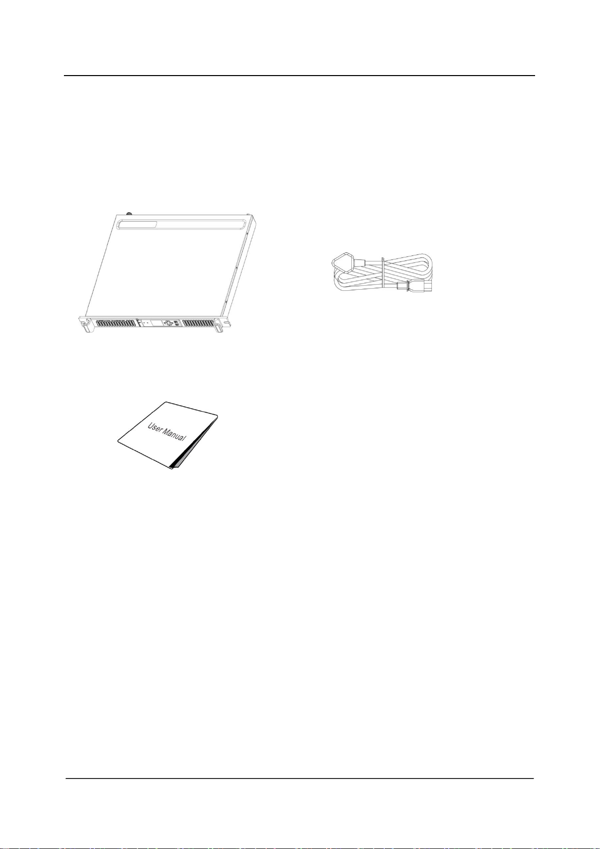
❶ Repeater
❷ Power Cord
❸ User Manual
Checking Items in the Package
Checking Items in the Package
Please unpack carefully and check that all items listed below are received. If any item is
missing or damaged, please contact your dealer.
4

No.
Part Name
No.
Part Name
1
Power Indicator
5
LCD Display
2
Alarm Indicator
6
Navigation Keys
3
RX Indicator
7
SET/EXIT Key
4
TX Indicator
8
Speaker
No.
Part Name
No.
Part Name
1
RX Connector (BNC)
7
DB9 Connector
2
Ground Screw
8
DB26 Connector
3
AC Power Inlet and Switch
9
SMA Connector
4
LED Indicators
Green LED: Indicates
power supply is normal
when lit.
10
RJ45 Ethernet Connector
Getting Started
Getting Started
Product Overview
Front Panel
Rear Panel
5

No.
Part Name
No.
Part Name
Blue LED: Indicates
overload or short circuit
occurs for the power
supply when lit.
Red LED: Indicates
reverse battery polarity
when lit.
5
DC Power Inlet/12V
Lead-acid Battery
11
TX or Duplexer Connector
(Type-N)
6
DB15 Connector
Getting Started
6

Getting Started
Installation Guide
Proper installation ensures the best possible performance and reliability of the repeater.
Therefore, be sure to read the following instructions before installation.
Installation Requirements
1. Installation Environment
The repeater must be installed in a dry and well-ventilated place with ambient
temperature of -30°C to +60°C and relative humidity of no more than 95%.
2. Installation Location
The repeater can be installed on a rack, bracket, and cabinet, or on a desk.
Caution: DO NOT place heavy objects on the repeater chassis.
Installation Steps
Install the repeater as follows:
1. Install the repeater at a proper location.
2. Attach all necessary accessories, like antenna feeder, power cord, data cable, etc.
3. Ground the repeater through the ground screw located on the rear panel.
Note:
If the DC power supply or 12V lead-acid battery is used to supply power to the
repeater, check and ensure that VDC or battery voltage is within the repeater
operating voltage range of 10.8V to 16.5V.
Check and make sure no blocking occurs for the air inlet on the front panel and the
cooling fan on the rear panel.
After turning on the repeater, check whether the repeater works properly by
observing the states of the Power and Alarm Indicators located on the front panel.
7

Getting Started
Parameter Configuration
When the repeater proves to work normally, configure appropriate parameters (e.g.
operating frequency, TX power, and signalling type) as per your actual requirements.
Caution: Disconnect the power supply to the repeater before opening the chassis.
8

Icon Name
Icon
Repeater Status
Scan Indicator
Scan is in progress when lit.
TX Power Indicator
Low TX power for the current
channel
High TX power for the current
channel
Network Connection
Indicator
Network connection is normal when
lit.
Slot Indicator
Repeater is transmitting or receiving
on slot 1 when lit.
Repeater is transmitting or receiving
on slot 2 when lit.
Channel Mode
Indicator
The current channel is an analog or
a digital channel.
LED Indicator
Repeater Status
Power Indicator
Repeater is connected to the power supply.
TX Indicator
The repeater is transmitting on a digital or an analog
channel.
RX Indicator
The repeater is receiving on a digital/an analog channel.
Alarm Indicator
The repeater works abnormally.
Getting Started
LCD Icon
LED Indicator
9

PC Repeater
Basic Operations
Basic Operations
Turning the Repeater On/Off
ON: Turn on the repeater by connecting an AC or a DC power supply to it. During the
power-up process, the Power indicator glows green and the LCD shows animation.
OFF: Disconnect the AC/DC power supply.
Reading from/Writing to a Repeater
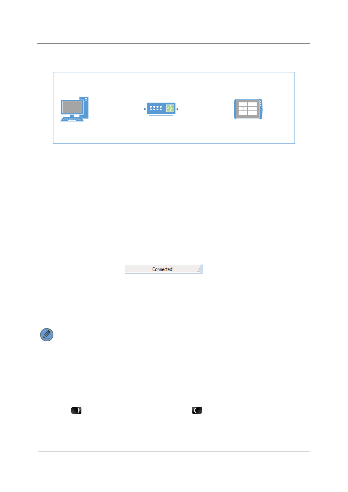
This option instructs the PC to read/write data from/to a repeater through the RJ45
Ethernet connector located at the rear panel of the repeater. The repeater could be
connected to the PC directly or to the PC via router in LAN.
Connecting Repeater to the PC Directly
1. Connect the repeater to the PC with an Ethernet cable (8-wire twisted pair cable).
2. Check the repeater IP address via menu operation.
3. Set the PC IP address to be in the same network segment as that of the repeater.
4. Click “Connect” at the CPS menu bar and then the Connect to Repeater window
appears.
5. Click “Scan” to search for the repeater to which the PC will connect.
6. Select the IP address and click “OK” to connect the repeater to the PC.
If connection is successful, is displayed at the CPS status bar.
Upon successful connection, you may click “Read” or “Write” at the CPS menu bar to
read from/write to the repeater.
10
RouterPC Repeater
LAN
Basic Operations
Connecting the Repeater to the PC via Router in LAN
1. Connect the repeater to the PC via the router in LAN using an Ethernet cable (8-wire
twisted pair cable).
2. Check the repeater IP address via menu operation.
3. Set the PC IP address to be in the same network segment as that of the repeater.
4. Click “Connect” at the repeater CPS menu bar and then the Connect to Repeater
window appears.
5. Click “Scan” to search for the repeater to which the PC will connect.
6. Select the IP address and click “OK” to connect the repeater to the PC.
If connection is successful, is displayed at the CPS status
bar.
Upon successful connection, you may click “Read” or “Write” at the CPS menu bar to
read from/write to the repeater.
Note: Before writing to the repeater, you may revert the PC IP address to its
previous one and set the repeater IP address to be in the same network
segment as that of the PC, to facilitate normal PC operation.
Adjusting the Volume
Press the key to increase the volume or the key to decrease the volume.
11

Basic Operations
Squelch Level
This option can reduce background noise by adjusting the squelch level when the
repeater is receiving signals. You may set the squelch level to Tight, Normal, or Open
using the repeater menu. Tight squelch level can filter weak signals, and allow only
strong signals to be received. If the squelch level is set to Open, the repeater will turn
on the speaker and background noise will be heard.
Follow the procedures below to set the squelch level.
Procedure:
1. In the home screen, press the SET key to enter the main menu.
2. Use the / key to select the “Function” option.
3. Press the SET key to enter the Function menu.
4. Use the / key to select the “Squelch Level” option.
5. Press the SET key to enter the Squelch Level menu.
6. Use the / key to select Open, Normal, or Tight.
7. Press the SET key to set the selected option as the squelch level.
To exit this menu, press the EXIT key.
Note: This feature is applicable to analog channels only.
12

Basic Operations
Scan
The Scan feature allows the repeater to search the scan list that is attached to the
current channel for an eligible channel to receive or unmute.
Before initiating the scan function using the repeater menu, follow the procedures
below to attach a scan list to the current channel using the CPS.
Procedure:
1. Log in to the CPS.
2. Go to “Conventional -> Scan -> Selected Scan List”.
3. Add channels (analog or digital) to be scanned into the Selected Scan List.
4. Go to “Conventional -> Channel -> Digital/Analog Channel -> Current Channel”.
5. In the Scan/Roam List option, attach the Selected Scan List to this channel.
After you have attached a scan list to the current channel, follow the following
procedures to start/stop scanning via menu operation.
Procedure:
1. In the home screen, press the SET key to enter the main menu.
2. Use the / key to select the “Function” option.
3. Press the SET key to enter the Function menu.
4. Use the / key to select the “Scan” option.
5. Press the SET key to enter the Scan menu.
6. Use the / key to select On or Off.
7. Press the SET key to save the settings in the system.
To exit this menu, press the EXIT key.
13
Basic Operations
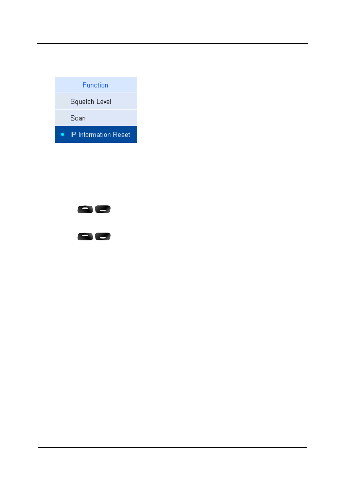
IP Information Reset
With this feature, you can restore IP information to factory defaults.
Follow the procedures below to restore IP information to factory defaults.
Procedure:
1. In the home screen, press the SET key to enter the main menu.
2. Use the / key to select the “Function” option.
3. Press the SET key to enter the Function menu.
4. Use the / key to select the “IP Information Reset” option.
5. Press the SET key and the prompt “IP Information Reset?” appears.
6. Press the SET key to restore IP information to factory defaults.
To exit this menu, press the EXIT key.
14

Basic Operations
Power Level
You may set the TX power to High or Low. High power can extend repeater coverage,
enabling you to communicate with farther terminals. The TX power is represented by the
icons and respectively on the LCD display.
Follow the following procedures to set the TX power.
Procedure:
1. In the home screen, press the SET key to enter the main menu.
2. Use the / key to select the “Power Level” option.
3. Press the SET key to enter the Power Level menu.
4. Use the / key to select High or Low.
5. Press the SET key to save the settings in the system.
To exit this menu, press the EXIT key.
Zone
A zone is a group of channels. Your repeater supports up to 128 channels and eight
zones (Zone 0 to Zone 7), with a maximum of 16 channels per zone.
Follow the following procedures to select a zone.
Procedure:
1. In the home screen, press the SET key to enter the main menu.
2. Use the / key to select the “Zone” option.
3. Press the SET key to enter the Zone menu.
4. Use the / key to select a zone.
5. Press the SET key to save the settings in the system.
To exit this menu, press the EXIT key.
15

Basic Operations
Backlight
This option allows users to control the backlight using the menu. Activating the backlight
can illuminate the LCD display, so as to facilitate your operation.
You may set the backlight to operate in any of the following modes:
Timed: Any key press operation can activate the backlight. If no foregoing event
occurs within the specified time period, the backlight will go out automatically.
Never: The backlight remains activated all the time.
Note: When an alarm event occurs, the backlight will remain activated until the
alarm disappears.
Follow the procedures below to set the backlight.
Procedure:
1. In the home screen, press the SET key to enter the main menu.
2. Use the / key to select the “Basic Settings” option.
3. Press the SET key to enter the Basic Settings menu.
4. Use the / key to select the “Display” option.
5. Press the SET key to enter the Display menu.
6. Use the / key to select the “Backlight Off Time” option.
7. Press the SET key to enter the Backlight Off Time menu.
8. Use the / key to select a desired time or Never.
9. Press the SET key to save the settings in the system.
To exit this menu, press the EXIT key.
16
Basic Operations
Brightness
This option allows users to adjust brightness (0–7) using the menu.
Follow the following procedures to set brightness.
Procedure:
1. In the home screen, press the SET key to enter the main menu.
2. Use the / key to select the “Basic Settings” option.
3. Press the SET key to enter the Basic Settings menu.
4. Use the / key to select the “Display” option.
5. Press the SET key to enter the Display menu.
6. Use the / key to select the “Brightness” option.
7. Press the SET key to enter the Brightness menu.
8. Press the / key to increase brightness or / to decrease
brightness.
9. Press the SET key to save the settings in the system.
To exit this menu, press the EXIT key.
17

Basic Operations
Menu Reset
This parameter allows users to define the amount of time that the repeater remains in
the menu mode. The counter will be activated after the repeater enters the menu. In
the event of no key press operation within the preset time period, the repeater will
automatically exit the menu.
You may set this feature as follows:
Timed: If no key press occurs within the specified time period, the repeater will
automatically return to the home screen.
Never: The radio user can manually exit the menu only.
Follow the procedures below to set the menu reset time.
Procedure:
1. In the home screen, press the SET key to enter the main menu.
2. Use the / key to select the “Basic Settings” option.
3. Press the SET key to enter the Basic Settings menu.
4. Use the / key to select the “Menu Reset” option.
5. Press the SET key to enter the Menu Reset menu.
6. Use the / key to select Never or a desired menu reset time.
7. Press the SET key to save the settings in the system.
To exit this menu, press the EXIT key.
18

Basic Operations
TX/RX LED
This option decides whether to give any LED alert when the repeater is transmitting
and/or receiving.
You can set the following TX/RX LED related parameters: All LEDs, TX LED, and RX
LED.
All LEDs: If the Enabled option is selected, TX LED and RX LED light when the
repeater is transmitting and receiving. If the Disabled option is selected, neither TX
LED nor RX LED lights when the repeater is transmitting and receiving.
TX LED: If the Enabled option is selected, TX LED lights when the repeater is
transmitting. If the Disabled option is selected, TX LED does not light when the
repeater is transmitting.
RX LED: If the Enabled option is selected, RX LED lights when the repeater is
receiving. If the Disabled option is selected, RX LED does not light when the
repeater is receiving.
Follow the procedures below to set TX/RX LED related parameters.
Procedure:
1. In the home screen, press the SET key to enter the main menu.
2. Use the / key to select the “Basic Settings” option.
3. Press the SET key to enter the Basic Settings menu.
4. Use the / key to select the “LED” option.
5. Press the SET key to enter the LED menu.
6. Use the / key to select any of the TX/RX LED related parameters among
All LEDs, TX LED, and RX LED.
7. Press the SET key to enter the LED submenu.
8. Use the / key to select Enabled or Disabled.
9. Press the SET key to save the settings in the system.
To exit this menu, press the EXIT key.
19

Basic Operations
Language
You can select a display language from the languages available in the repeater. This
repeater supports English and Simplified Chinese.
Follow the following procedures to select a display language.
Procedure:
1. In the home screen, press the SET key to enter the main menu.
2. Use the / key to select the “Basic Settings” option.
3. Press the SET key to enter the Basic Settings menu.
4. Use the / key to select the “Language” option.
5. Press the SET key to enter the Language menu.
6. Use the / key to select Simplified Chinese or English.
7. Press the SET key to save the settings in the system.
To exit this menu, press the EXIT key.
20

Basic Operations
Locking/Unlocking the Repeater
This repeater is equipped with Keypad Lock capability to prevent accidental key
operation.
Lock: You can set whether to allow the repeater to automatically lock the keys on
the front panel and the auto lock delay time.
Unlock: Press the key and then the SET key to unlock the keys on the front
panel.
Follow the following procedures to set this feature.
Procedure:
1. In the home screen, press the SET key to enter the main menu.
2. Use the / key to select the “Basic Settings” option.
3. Press the SET key to enter the Basic Settings menu.
4. Use the / key to select the “Keypad Lock” option.
5. Press the SET key to enter the Keypad Lock menu.
6. Use the / key to select Never or an auto lock delay time.
7. Press the SET key to save the settings in the system.
To exit this menu, press the EXIT key.
21

Menu Navigation
Menu Navigation
Repeater Information
Under this menu, you can use the / key to view repeater information,
including Model Type, Model Number, Data Version, Firmware Version, and Frontboard
Version.
Follow the procedures below to view repeater information.
Procedure:
1. In the home screen, press the SET key to enter the main menu.
2. Use the / key to select the “Repeater Information” option.
3. Press the SET key to enter the Repeater Information menu.
4. Press the / key to view basic information of the repeater.
To exit this menu, press the EXIT key.
Channel Information
Under this menu, you can use the / key to view channel information,
including Channel Alias, TX Frequency, RX Frequency, Channel Spacing, TX
CTCSS/CDCSS Type, and RX CTCSS/CDCSS Type.
22

Menu Navigation
Follow the procedures below to view channel information.
Procedure:
1. In the home screen, press the SET key to enter the main menu.
2. Use the / key to select the “Channel Information” option.
3. Press the SET key to enter the Channel Information menu.
4. Press the / key to view channel information.
To exit this menu, press the EXIT key.
IP Information
Under this menu, you can use the / key to view IP information, including IP
Address, Subnet Mask, Default Gateway, and MAC Address.
Follow the procedures below to view IP information.
Procedure:
1. In the home screen, press the SET key to enter the main menu.
2. Use the / key to select the “IP Information” option.
3. Press the SET key to enter the IP Information menu.
4. Use the / key to view IP information.
To exit this menu, press the EXIT key.
23

No.
Element
1
Alarm Icon
2
Alarm Message
3
Alarm Code (0–8)
0: POST Error
1: Fan Failure
2: Over Temperature
3: Low Forward Power (reserved)
4: High VSWR
5: TX Unlock
6: RX Unlock
7: Over Voltage
8: Low Voltage
4
Alarm Count
Alarm Information
Alarm Information
The repeater can automatically detect its operation status in a real time way. When an
abnormality occurs, the LCD display will give you a prompt message, and the Alarm
Indicator will glow red.
Alarm Window
24

Alarm Information
POST Error Alarm
The principal duties of the system during POST are as follows:
verify fan
verify LCD display
verify TX circuit
verify RX circuit
verify active duplexer circuit
When an error occurs during POST, abnormality of partial functions happens and the
system runs normally. In addition, the Alarm Indicator will glow red and the LCD
display will give you the prompt message below:
You need to:
1. Disconnect the power supply, open the chassis, and check whether the LCD
display is properly connected or damaged.
2. Disconnect the power supply and open the chassis to check whether the fan works
properly.
3. Disconnect the power supply and open the chassis to check if the hardware cable
gets loose or damaged. If yes, secure or replace the hardware cable.
4. If you cannot solve the problem, contact your local dealer for technical support.
25

Alarm Information
Fan Failure Alarm
When the fan fails to work, the Alarm Indicator will glow red and the LCD display will
give you the prompt message below:
Then the repeater will automatically work at low TX power to protect the transmitter from
overheating.
You need to:
1. Check whether the fan is blocked by an object. If yes, remove it.
2. If you cannot solve the problem, contact your local dealer for technical support.
When the fan restores to normal operation, the prompt message will disappear and the
Alarm Indicator will go out.
26

Alarm Information
Over Temperature Alarm
When the temperature of the PA module exceeds the normal range, the Alarm Indicator
will glow red and the LCD display will give you the prompt message below:
Then the repeater will stop transmitting, and you need to:
1. Check whether the Fan Failure Alarm prompt message appears on the LCD display.
If yes, refer to measures taken in Fan Failure Alarm.
2. Check whether ambient temperature and ventilation conditions satisfy the foregoing
installation requirements. If not, please make improvements as soon as possible.
For example, install more air conditioners for optimal ventilation.
3. Check if the RF cable or antenna feeder that is connected to the transmitter is loose
or damaged. Poor connection between them could cause high TX power. If yes,
secure or replace the cable or antenna feeder.
4. If the above measures fail to solve the problem, contact your local dealer for
technical support.
When repeater temperature falls into the normal range, the prompt message will
disappear and the Alarm Indicator will go out.
27

Alarm Information
VSWR Alarm
High voltage standing wave ratio (VSWR) of TX antenna connector could result in
damage to the PA, and even failure of the transmitter. When the VSWR exceeds the
normal range, the Alarm Indicator will glow red and the LCD display will give you the
prompt message below:
Then the repeater will automatically works at low TX power.
You need to:
1. Check whether the operating frequency of the repeater is in line with that of antenna.
Both frequency mismatch and improper antenna could result in poor transmitting
performance and even damage to the transmitter. If yes, please contact your local
dealer to replace the antenna or program the repeater again.
2. Check if the RF cable or antenna feeder that is connected to the transmitter gets
loose or damaged. If yes, secure or replace the cable or antenna feeder.
3. If you fail to solve the problem, contact your local dealer for technical support.
When the VSWR falls within the normal range, the prompt message will disappear and
the Alarm Indicator will go out.
28

Alarm Information
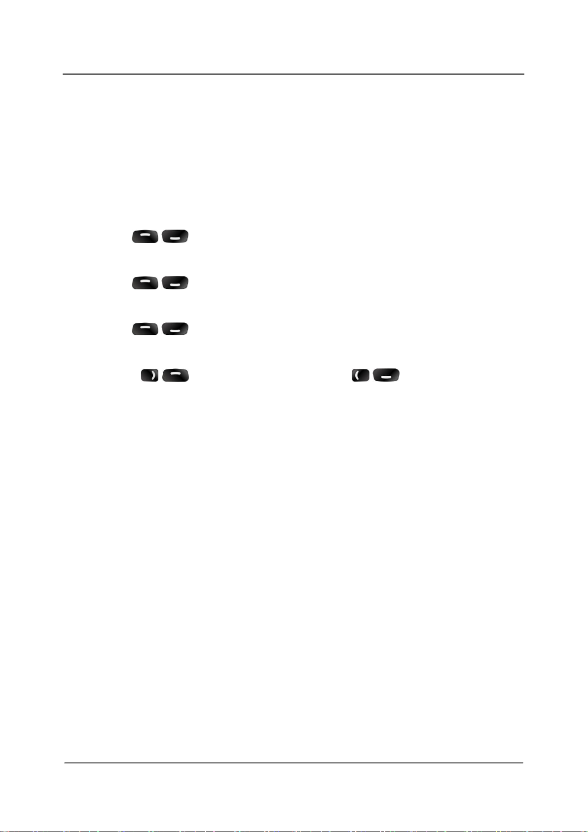
TX/RX Unlock Alarm
When the TX/RX PLL is unlocked, the Alarm Indicator will glow red and the LCD display
will give you the prompt message below:
TX Unlock Alarm RX Unlock Alarm
Then the repeater will automatically stop partial operations and the prompt message will
remain on the LCD display.
You need to:
1. Disconnect the power supply, open the chassis, and check whether the hardware
cable gets loose or damaged. If yes, please secure or replace the cable.
2. If you cannot solve the problem, contact your local dealer for technical support.
When the TX/RX PLL restores to normal operation, the prompt message will disappear
and the Alarm Indicator will go out.
Caution: Disconnect the power supply prior to opening the chassis!
29

Alarm Information
Over/Low Voltage Alarm
When power voltage is detected to be over or below the normal range (10.8V–15.6V)
of repeater, the Alarm Indicator will glow red and the LCD display will give you the
prompt message below:
Over Voltage Alarm Low Voltage Alarm
Then the repeater will automatically stop working and the prompt message will remain
on the LCD display.
You need to:
1. Check whether the power voltage is too low or too high. If yes, replace the DC
power supply or external battery.
2. Check if the power cord gets loose or damaged. If yes, secure or replace the cord.
3. If you fail to solve the problem, contact your local dealer for technical support.
When the voltage falls within the normal range, the prompt message will disappear and
the Alarm Indicator will go out.
Caution: If low voltage is detected when the repeater is powered by an external
battery, please charge it in time. Disconnect the battery from the repeater before
charging.
30
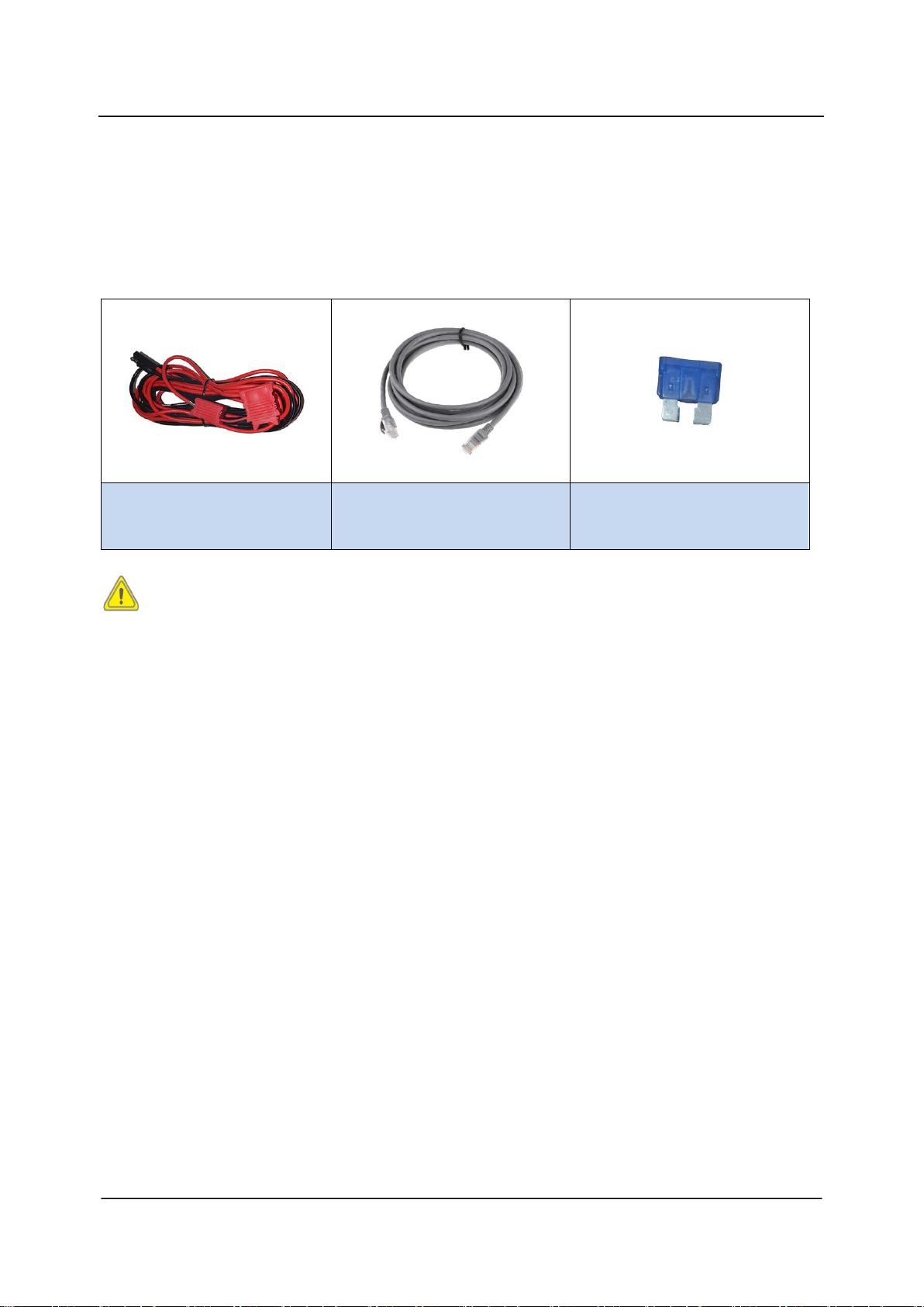
Power Cord
EPWCAZ01
Programming Cable
EPC03
Fuse
EACC001
Optional Accessories
Optional Accessories
The following items are the main optional accessories for the product. Consult your local
dealer for more other accessories.
Caution: Use the accessories specified by the Company only. If not, we shall not
be liable for any damage arising out of use of unauthorized accessories.
31

Phenomena
Analysis
Solution
The repeater cannot be
powered on.
Power cord is not connected
or is not securely connected
to the outlet.
Properly connect the power
cord and secure connection.
Power cord fuse is damaged.
Check whether the fuse has
blown. If yes, replace it with a
new one.
Group members cannot talk to
each other, or the repeater
cannot communicate with a
subscriber radio.
TX/RX frequency of the
repeater is inconsistent with
that of portable/mobile
terminals.
Reset frequencies.
Failed to repeat useful signal
due to strong interference
signal.
If you cannot remove or bypass
the interference source, change
or operate at other frequencies.
The group member is out of
the coverage of the repeater.
Go within the coverage of the
repeater.
Group members cannot talk to
each other, even though RX
indication is given.
Your ID is inconsistent with
that of other group members.
Set your ID to be the same as
that of other members.
Inconsistent CTCSS/CDCSS
Reset CTCSS/CDCSS.
Short communication range or
poor audio
Leakage of signal energy due
to damaged connection
cable.
Replace the cable with a new
one if necessary.
Loose connection between
the antenna connector and
the cable, or loss of
connection
Secure or replace the cable.
Troubleshooting
Troubleshooting
32

Phenomena
Analysis
Solution
Invisible damage of cable
Replace the cable with a new
one.
Duplexer is not properly set (if
the duplexer is mounted).
Contact the manufacturer or
your dealer to reset the
duplexer.
Troubleshooting
If the above solutions cannot fix your problems, or you may have some other queries,
please contact us or your local dealer for more technical support.
33

Care and Cleaning
Care and Cleaning
To guarantee optimal performance as well as a long service life of the product, please
follow the tips below. Power off the repeater or disconnect it from the external battery
before cleaning.
Product Care
Keep the product at a place of good ventilation and heat dissipation to facilitate
normal work.
Do not place irrelevant articles on the top of the product to ensure optimal heat
dissipation.
Do not pierce or scrape the product with any edged instruments or hard objects.
Keep the product far away from substances that can corrode the circuit.
Do not place the product in corrosive agents, solutions, or water.
Product Cleaning
Remove the dust and fine particles on the repeater surface with a clean and dry
lint-free cloth or a brush regularly.
Use a non-woven cloth with neutral cleanser to clean the keys, control knobs, LCD,
and connectors after long-time use. Never use chemical preparations such as stain
removers, alcohol, sprays, or oil preparations. Make sure the product is completely
dry before use.
34

ER9000 Digital Repeaters
Two Years
Accessories
Six Months
Limited Warranty
Limited Warranty
What This Warranty Covers and for How Long
The Company warrants the manufactured products listed below against defects in
material and workmanship under normal use and service for a period of time from the
date of purchase as scheduled below:
How to Get Warranty Service
You must provide a completely filled warranty card, purchase invoice, and receipt in
order to get warranty services. The purchase invoice or receipt should indicate the
repeater, accessories, repeater serial number, purchase date, and purchase amount.
What This Warranty Does Not Cover
1. Defect or damage resulting from use of the product in other than its normal and
customary manner
2. Defect or damage caused by unauthorized product disassembly, repair, or
modification
3. Damage due to force majeure, such as flood, lightning strike, earthquake, tsunami,
fire, and abnormal voltage
4. Product that does not have proof of purchase, such as warranty card, purchase
invoice, or receipt
5. Product which has had the serial number and the tamper-proof label removed or
made illegible
6. Normal and customary wear and tear
35

Disclaimer
Disclaimer
The information in this manual is carefully examined and is believed to be entirely
reliable. However, no responsibility is assumed for inaccuracies. All the specifications
and designs are subject to change without notice due to continuous technology
development. No part of this manual may be copied, modified, translated, or
distributed in any manner without the prior written permission of the Company.
36

Warranty Card
Warranty Card
Purchase Information
Customer Name:
Customer Phone:
Customer Address:
Purchase Date:
Repeater Information
Model Number:
Serial Number:
Note:
This warranty card applies to after-sale and maintenance services for the product
and accessories described above.
You must provide this warranty card and purchase invoice in order to get warranty
services.
The Company does not assume liability for damages caused by human factors.
For more details, contact your local dealer.
37

38
 Loading...