

Digital Portable Radio
Digital Portable Radio
User Manual
User Manual
U1
i
Contents
13
13
12
13
Analog Conventional Functions and Operations
14
14
14
14
14
14
15
16
19
17
Digital Conventional Functions and Operations
12
12
12
Color Code
Man Down
Group Call
All Call
Calls on Analog Channels
CTCSS/CDCSS Type
CTCSS
CDCSS
CDCSS Invert
Optional Accessories
Limited Warranty
Troubleshooting
Warranty Card
Call
Private Call
1
Radio Saftety Information and RF Radiation Information
4
RF Energy Exposure Information
Operation Safety Recommendations
2
3
7
Preparing Your Radio for Use
7
7
8
8
8
Checking Items in the Package
6
9
10
5
11
Switching the Channel Mode
11
Setting the Programmable Buttons
11
11
11
11
11
11
Important Information
Getting Started
Charging the Battery
Attaching the Battery
Attaching the Antenna
Attaching the Belt Clip
Radio Controls
LED Indicator
Alert Icon
Basic Operations
Adjusting the Volume
Adjusting Power Level
Selecting a Channel
Transmit Time-Out
Selecting a Zone
12.0 mm
12.0 mm
Ibefore using the two-way portable radio, review the following important RF energy awareness and control information and operational
instructions. Comply with this information and instructions in order to ensure compliance with RF exposure guidelines.e the capability to
access information in that form.
This two-way radio uses electromagnetic energy in the radio frequency (RF) spectrum to provide communications between two or more
users over a distance. It uses RF energy or radio waves to send and receive calls. RF energy is one form of electromagnetic energy. Other
forms include, but are not limited to, electric power, sunlight, and x-rays. RF energy, however, should not be confused with these other
forms of electromagnetic energy, which, when used improperly, can cause biological damage. Very high levels of x-rays, for example, can
damage tissues and genetic material.
Experts in science, engineering, medicine, health, and industry work with organizations to develop standards for exposure to RF energy.
These standards provide recommended levels of RF exposure for both workers and the general public. These recommended RF exposure
levels include substantial margins of protection. All two-way radios marketed in North America are designed, manufactured, and tested to
ensure they meet government-established RF exposure levels. In addition, manufacturers also recommend specific operating instructions
to users of two-way radios. These instructions are important because they inform users about RF energy exposure and provide simple
procedures on how to control it. Refer to the following websites for more information on what RF energy exposure is and how to control
exposure to assure compliance with established RF exposure limits:
http://www.fcc.gov/oet/rfsafety/rf-faqs.html
http://www.osha.gov./SLTC/radiofrequencyradiation/index.html
RF Ene rgy Exp os ure Awar eness And Contr ol
Info rmati on F or Fcc Oc cupat io nal Use R equir ements
This radio is intended for use in occupational/controlled conditions, where users have full knowledge of their exposure
and can exercise control over their exposure to remain below RF exposure limits. This radio is NOT authorized for
general population, consumer, or any other use.
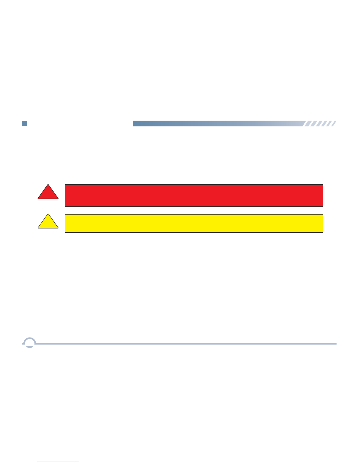
!
Changes or modifications not expressly approved by Shenzhen Excera Technology Co., Ltd.could void the user's
authority to operate the equipment.
WARNING
!
CAUTION
RF Energy Exposure Information
Important Information
2

To ensure bodily exposure to RF electromagnetic energy is within the FCC allowable limits for occupational use. Always adhere to
the following basic guidelines:
•
The push-to-talk button should only be depressed when intending to send a voice message.
• The radio should only be used for necessary work-related communications.
• The radio should only be used by authorized and trained personnel. It should never be operated by children.
• Do not attempt any unauthorized modification to the radio. Changes or modifications to the radio may cause harmful
interference and/or cause it to exceed FCC RF exposure limits. Only qualified personnel should service the radio.
Occup ational Safe ty Guideline s And Safety Training Information
Feder al Communica tions Commis sion Regulat ions
Before it was marketed in the United States, the Digital portable radio was tested to ensure compliance with FCC RF energy
exposure limits for two-way portable radios. When two-way radios are used as a consequence of employment, the FCC requires
users to be fully aware of and able to control their exposure to meet occupational requirements. Exposure awareness can be
facilitated by the use of a
label directing users to specific user awareness information. The radio has an RF exposure product label.
Also, the Product Safety Manual and this Operator’s Manual include information and operating instructions required to control RF
exposure and to satisfy compliance requirements.
Opera tion Safety Re commendations
Important Information
3
• Hold the r adio in a vertical position in front of face with the microphon e (and the othe r
parts of the radio, including the antenna) at least one inch (2.5 cm) away from the nose.
Keeping the radio at the proper distance is important because RF exposur es decrease
with distance from the antenna. Antenna should be kept away from eyes.
• When worn on the body , always place the radio in a Excera’s approve d clip, holde
holster, case, or body harness for this product. Using approved body-worn accessories is
important because the use of Excera’s or other manufacturer’s non-approved accessories
may result in exposure levels, which exceed the FCC’s occupational/controlled
• Hold the r adio in a vertical position in front of face with the microphon e (a nd the othe r
parts of the radio, including the antenna) at least one inch (2.5 cm) away from the nose.
Keeping the radio at the proper distance is important because RF exposur es decrease
with distance from the antenna. Antenna should be kept away from eyes.
• When worn on the body , always place the radio in a Excera’s approve d clip, holde
holster, case, or body harness for this product. Using approved body-worn accessories is
important because the use of Excera’s or other manufacturer’s non-approved accessories
may result in exposure levels, which exceed the FCC’s occupational/controlled
• Hold the r adio in a vertical position in front of face with the microphon e (and the other
parts of the radio, including the antenna)
Keeping the radio at the proper distance is important bec
ause RF exposure
with distance from the antenna. Antenna should be kept away from eyes.
• When worn on the body , always place the
radio in a Excera’s approve d clip, holde
holster, case, or body harness for this prod
uct. Using approved body-worn accessories is
important because the use of Excera’s or other manufacturer’s non-approved accessories
may result in exposure levels, which
exceed the FCC’s occupational/controlled
environment RF exposure limits.
at least one inch (2.5 cm) away from the nose.
decrease
CAUTION :
RISK OF EXPLOSION IF BATTERY IS REPLACED BY AN INCORRECT TYPE. DISPOSE OF USED BATTERIES
ACCORDING TO THE INSTRUCTIONS.
Adapter shall be installed near the equipment and shall be easily accessible.
The max operating of the device is 55℃.
EU Regula tory Confo rmance
As certified by the qualified laboratory, the product is in compliance with the essential requirements and other relevant provisions of
the Directive 199/5/EC.Please note that the above information is applicable to EU countries only.
Radio Frequency Interference
FCC Part 15
Industry Canada
This device complies with Part 15 of the FCC Rules. Operation is subject to the following two conditions:
1. This device may not cause harmful interference; and,
2. This device must accept any interference received, including interference that may cause undesired operation.
This device complies with Industry Canada license-exempt RSS standard(s). Operation is subject to the following two conditions: (1) this device may
not cause interference, and (2) this device must accept any interference, including interference that may cause undesired operation of the device.
Le présent appareil est conforme aux CNR d'Industrie Canada applicables aux appareils radio exempts de licence. L'exploitation est autorisée aux
deux conditions suivantes : (1) l'appareil ne doit pas produire de brouillage, et (2) l'utilisateur de l'appareil doit accepter tout brouillage radioélectrique
subi, même si le brouillage est susceptible d'en compromettre le fonctionnement.
Important Information
4
T
he device has been tested and compliance with SAR limits, users can obtain Canadian information on
RF exposure and compliance
Après examen de ce matériel aux conformité aux limit es DAS et/ou aux limites d’intensité de champ RF,
l’exposition aux radiofréquen
es et la conformité and compliance d’acquérir
les informations correspondantes
les utilisateurs peuvent sur
Hold the radio in a vertical position in front of face with the microphone at least one inch(2.5cm)away from the nose.
Keeping the radio at the proper distance is important because RF exposures decrease with distance from the antenna.Antenna should be kept away from eyes.
Important Information
5
Before using this product, please read this user manual carefully.
■
Alert Icon
Cauti on:
Indicates situations that could cause human injury or damage to your products.
Note:
Indicates tips that can help you make better use of your products.
Cauti on:

Please unpack carefully and check that all items listed below are received. If any item is missing or damaged,
please contact your dealer.
Radio Battery
Power Adapter Antenna
Belt Clip
Use r Ma
nua
l
User Manual
Charger
Strap
Checking Items in the Package
6

LED Ind icator
LED Indicator
Charger Status
LED flashes red slowly. Standby (no load)
LED glows red.
Charging
LED glows orange.
90% charged
LED glows green. Fully charged
LED flashes red rapidly.
Failure
■
Preparing Your Radio for Use
Charging the Battery
Procedure
Charg ing Diagram
1
2
3
3
1
7
For best performance, your radio is powered by an
Excera manufactured Lithium-Ion (Li-Ion) battery. To
avoid damage and comply with warranty terms, charge
the battery using the charger contained in the package.
1. Plug the power adapter into the rear jack of the charger.
See arrow ①.
2. Connect the power adapter to AC socket. See arrow ②.
3. Place the radio with the battery attached, or the battery
alone, into the charger. See arrow ③.
The charging process begins when the charger LED glows red
and is completed when the LED glows green.
Getting Started

Attaching the Antenna
Attaching the Battery
1. Align the battery with the rails on the rear of the radio as
shown by arrow ①.
2. Slide the battery upward to the top of the rails and snap
the latch into place as shown by arrow ②.
To attach the antenna, set the antenna in its receptacle and
turn clockwise.
To remove the battery, turn off the radio first. Move the
battery latch into unlock position and hold, and slide the
battery down and off the rails.
Attaching the Belt Clip
1. Remove the screws.
2. Align the screw holes on the belt clip with those on the
radio’s body, and then tighten the screws.
To remove the antenna, turn the antenna counterclockwise.
1
2
Getting Started
8
Note: You need to turn off the radio prior to attaching or
removing the antenna.

No.
Part Name
No. No.
Part Name Part Name
SK1 (Side Key 1)
SK2 (Side Key 2)
Radio On-Off/Volume Control Knob
Microphone (Half Duplex)
Microphone (Full Duplex)
TK (Top Key)
Belt Clip
PTT Key
Channel Selector Knob
LED Indicator
Speaker
Antenna
Accessory Jack
Battery
■
Radio Controls
9
Getting Started

■
LED Indicator
LED Indicator
Radio Status
LED flashes green rapidly.
Upgrading or powering on
LED glows green. Receiving
LED flashes red slowly.
Low battery
None
Transmitting
LED flashes orange slowly. Scanning
No voice is being transmitted
or received on the traffic
channel after a call is
established. Within such
period, you can hold down
the PTT key to talk.
LED flashes red rapidly.
LED glows red.
LED flashes orange rapidly.
LED glows orange.
None
10
Getting Started

11
Basic Operations
■
Switching the Channel Mode
This radio can operate in either digital or analog
conventional mode.
Each channel can be programmed as either analog or
digital channel via the CPS. If the current zone includes
a mixture of analog and digital channels, you may
quickly switch between digital and analog through the
Channel Selector knob.
■
Setting the Programmable Buttons
You may set the programmable buttons (SK1, SK2, and
TK) as shortcuts to radio functions (such as power level
switch, zone switch, or squelch level) using the CPS.
■
Adjusting the Volume
After turning the radio on or during a call, rotate the
Radio On-Off/Volume Control knob clockwise to
increase the call volume, or counterclockwise to
decrease it.
■
Adjusting Power Level
With this option, you may toggle power levels quickly.
We recommend you to adopt low power for battery
■
Selecting a Channel
After turning the radio on, rotate the Channel Selector
knob to select a desired channel. In the process, you
will hear the sequence number of the selected channel
in the Zone Member list.
■
Selecting a Zone
A zone is a group of channels exhibiting the same
property. The radio supports 32 zones and each zone
contains 16 channels at most.
You may quickly toggle to your desired zone by
pressing the programmed Zone Up or Zone Down key.
■
Transmit Time-Out
The purpose of Transmit Time-Out is to prevent any
user from occupying a channel for an extended period.
If the preset time expires, the radio will automatically
terminate the transmission.
You may set the time via the CPS.
saving. However, if you cannot communicate with
radios located at a distant place with low power, please
select high power.

12
Digital Conventional Functions and Operations
■
Call
To ensure that your speech is clear, keep the
microphone 2.5 to 5 cm from your mouth.
Private Call
A private call is a call from an individual radio to another
individual radio.
Making a Private Call
In standby mode, hold down the PTT key to make a
private call to the private call contact preset for the
current channel.
Receiving and Responding to a Private Call
When a private call is received, you can listen to it
without any operation and you may hold down the PTT
key within the preset time period to call back.
Group Call
A group call refers to a call from an individual radio to a
group of radios.
Receiving and Responding to a Group Call
When a group call is received, you can listen to it
without any operation and you may hold down the PTT
key within the preset time period to call back.
Late Entry
After a group call is established, it allows other group
members to join this call.
Late entry may occur in any of the following situations:
● The radio is powered on.
The Channel Selector knob is rotated to the channel ●
in operation.
The radio is within the communication coverage of ●
this group call.
Making a Group Call
In standby mode, hold down the PTT key to make a
group call to the group call contact preset for the
current channel.

13
All Call
An all call is a call from an individual radio to every
radio on the channel.
Making An All Call
In standby mode, hold down the PTT key to make the all
call to the all call contact preset for the current channel.
■
Color Code
Color code is used to identify a system. Users who wish
to communicate with each other are assigned with the
same color code. A radio ignores the channel activity
which does not match the preset color code in this field,
as it assumes the activity belongs to other systems.
You may set this feature via the CPS.
Note: The All Call ID is fixed and is set via the CPS.
Rx Group List
With this option, you can receive multiple group calls on
a digital channel.
A Rx group list contains a maximum of 32 group
contacts. You can set up to 32 Rx group lists using the
CPS, each of which can be associated with a digital
channel.
■
Man Down
Once this feature is activated, if you radio tilts to a
specified gradient and is not placed upright within Man
Down Delay Time, it will enter the emergency mode.
This feature will be valid if is checked in the CPS.
Digital Conventional Functions and Operations

Analog Conventional Functions and Operations
14
■
Calls on Analog Channels
To transmit on an analog channel, hold down the PTT
key and speak into the microphone. To receive, release
the PTT key.
■
CTCSS/CDCSS Type
This option allows you to configure the current channel
with a specific Rx CTCSS/CDCSS type. When the radio
receives the signal, it will distinguish whether the
received signal is CTCSS or CDCSS, and check out
whether it matches the predefined CTCSS/CDCSS for
the current channel before processing.
Three types are available: CTCSS, CDCSS, and
CDCSS Invert.
CTCSS
Procedure:
1. Log in to the CPS.
The radio checks for CTCSS match when receiving a
signal on the current channel.
Follow the procedure below to set CTCSS/CDCSS Type
to CTCSS.
CDCSS
The radio checks for CDCSS match when receiving a
signal on the current channel.
Follow the procedure below to set CTCSS/CDCSS Type
to CDCSS.
Procedure:
1. Log in to the CPS.
2. Go to “Conventional -> Channel –> Analog Channel
-> Selected Analog Channel” and set Rx/Tx CTCSS
/CDCSS Type to CDCSS.
CDCSS Invert
The radio checks for an invert CDCSS match when
receiving a signal on the current channel.
Follow the procedure below to set CTCSS/CDCSS Type
to CDCSS Invert.
Procedure:
1. Log in to the CPS.
2. Go to “Conventional -> Channel –> Analog Channel
-> Selected Analog Channel” and set Rx/Tx CTCSS
/CDCSS Type to CDCSS Invert.
Note: CDCSS is also known as DCS.
2. Go to “Conventional -> Channel –> Analog Channel
-> Selected Analog Channel” and set Rx/Tx CTCSS
/CDCSS Type to CTCSS.

The following items are the main optional accessories for the product. Consult your local dealer for more other accessories.
C-Shell Earset
EEHN011
Bluetooth Headset
EEWB03E
Optional Accessories
Caution: Use the accessories specified by the Company only. Otherwise, the Company shall not be liable for losses
or damages arising out of use of unauthorized accessories.
Wireless PTT
EPTTB01
Programming Cable
EPC01
Remote Speaker
Microphone
EMRN01
1
1-Wire Earpiece with
Transparent Acoustic Tube
EEAN011
Police Full Bone
Conduction Headset
EEBN011
Fireman Full Bone
Conduction Headset
EEBN021
Multi-unit Charger
EMC702L
2-Wire Earpiece with
Transparent Acoustic Tube
EEAN021
15

Troubleshooting
Phenomena
Analysis
Solution
If the above solutions cannot fix your problems, or you may have some other queries, please contact us or your local dealer for more technical support.
The radio cannot be
powered on.
The battery may be improperly installed.
The battery may run out.
The radio may not detect signals from the
base station.
The radio may not be authorized.
The radio registers repeatedly.
No voice is h ea rd a fter a call
is establ is hed.
The called party disconnects
repeatedly during communication.
During receiving, the voice is
weak, discontinuous, or totally
inactive.
You cannot communicate with
other members.
The voice is unclear.
The signal is discontinuous.
Your ID may be repeated.
The signal is discontinuous.
Low battery
The volume may be set to a low level.
The antenna may get loose or improperly
installed.
The speaker may be blocked or damaged.
The signal is poor.
You may suffer from external disturbance
(such as electromagnetic interference).
Remove the battey and attach it again.
Recharge or replace the battery.
Clean the battery contacts. If the problem cannot be solved, contact your
dealer or authorized service center for inspection and repair.
Make sure you are within the coverage of the base station.
Contact the base station manager to check whether you are an authorized
subscriber in the network management system.
Contact the base station manager to check whether your ID is repeated in the
network management system.
Recharge or replace the battery.
Move to an open and flat area and restart the radio.
Increase the volume by rotating the Volume Control knob clockwise.
Power off the radio, reinstall the antenna and power on the radio again.
Clean surface of the speaker. If the problem cannot be solved, contact your local
dealer or authorized service center for inspection and repair.
Make sure you are within the communication range.
Stay away from equipment that may cause interference.
You may be at an unfavorable position. For
example, your communication may be blocked
by high buildings or frustrated in the
underground areas.
The battery may suffer from poor contact
caused by dirty or damaged battery contacts.
The radio cannot register
successfully.
Make sure you are within the coverage of the base station.
Make sure you are within the coverage of the base station.
The signal is poor.
The radio cannot establish a
call.
Make sure you are within the coverage of the base station.
The signal is poor.
The signal is poor.
The noise is too loud.
Make sure you are within the communication range.
Make sure you are within the communication range.
16

Limited Warranty
Shenzhen Excera Technology Co., Ltd. warrants the Excera manufactured products listed below against defects in material and
workmanship under normal use and service for a period of time from the date of purchase as scheduled below:
EP8000 Digital Portable Radios
Two Years
Six Months
Accessories
How to Get Warranty Service
You must provide a completely filled warranty card, purchase invoice, and receipt in order to get warranty services. The purchase
invoice or receipt should indicate the radio, accessories, radio serial number, purchase date, and purchase amount.
What This Warranty Does Not Cover
1. Defect or damage resulting from use of the product in other than its normal and customary manner
2. Defect or damage caused by unauthorized product disassembly, repair, or modification
3. Damage due to force majeure, such as flood, lightning strike, earthquake, tsunami, fire, and abnormal voltage
4. Product that does not have a valid warranty certificate, such as warranty card, purchase invoice, or receipt
5. Product which has had the serial number and the tamper-proof label removed or made illegible
6. Normal and customary wear and tear
7. Rechargeable batteries if:
(1) any of the seals on the battery enclosure of cells is broken or shows evidence of tampering.
(2) the damage or defect is caused by charging or using the battery in equipment or service other than the product for which
it is specified.
What This Warranty Covers and for How Long
17

Customer Name:
Customer Phone:
Customer Address:
Purchase Date:
Warranty Card
Please tea r from the Dotted line
Purchase Information
Model Number:
Serial Number:
Radio Information
Note:
●
This warranty card applies to after-sale and maintenance services for the product and accessories described above.
●
You must provide this warranty card and purchase invoice in order to get warranty services.
●
The Company does not assume liability for damages caused by human factors. For more details, contact your local dealer.

 Loading...