

Page 1
STB-4000 User Guide
Manual Version Release 1.0
Page 2

STB-4000 User Guide
Copyright and Distribution Notice
December 2015
Copyright © 2015
Exceptional Innovation Inc.
ALL RIGHTS RESERVED
Exceptional Innovation Software and Hardware
This documentation, the Exceptional Innovation software and hardware products and services
it describes, and the information and know-how they contain constitute the proprietary,
condential and valuable trade secret information and sole property of Exceptional Innovation
Inc. and may not be used for any unauthorized purpose, or disclosed to others without the
prior written permission of the applicable Exceptional Innovation entity.
Duplication, in whole or in part, if and when permitted, shall bear this notice and Exceptional
Innovation copyright notice. As and when provided to any governmental entity, government
contractor or subcontractor subject to FARs, this documentation is provided with
RESTRICTED RIGHTS.
Third-Party Software and Hardware
Other product and company names or logos mentioned herein may be the trademarks of their
respective owners.
Distribution
Distribution of this document is limited to Exceptional Innovation employees, partners,
clients, or other third parties with whom a non-disclosure agreement has been reached. Any
distribution of this document external to Exceptional Innovation without the express consent
of one of its ofcers is strictly prohibited.
Inquiries
Mail Inquiries:
Exceptional Innovation Inc.
480 Olde Worthington Road
Suite 350
Westerville, Ohio 43082
Phone: (614) 860-6090
Fax: (614) 860-6091
Online Inquires:
www.exceptionalinnovation.com
ii
Page 3

Table of Contents
Features, Specications,
and Safety Information ............................. 1-1
Overview ................................................................................... 1-1
About the STB-4000 ................................................................. 1-1
Unit Features ............................................................................ 1-2
Rear Panel Connections ..............................................1-3
Care and Maintenance .............................................................1-4
Protection from Impact ................................................1-4
Cleaning ......................................................................1-4
Technical Specications ...........................................................1-5
Important Safety Information ....................................................1-6
Safety Instructions ....................................................... 1-6
Regulatory Information ................................................1-7
Warnings ......................................................................1-8
Installation and Setup ............................... 2-1
Overview ................................................................................... 2-1
Items Included with the STB-4000 ...............................2-1
Items Included in the STB-4000 Cable Kit ...................2-1
Items Required for Installation .................................... 2-1
Optional Items for Installation ...................................... 2-1
Install an STB-4000 .................................................................. 2-2
Connect the STB-4000 to the network ........................2-2
Connect the STB-4000 to the TV.................................2-3
Connect the STB-4000 to Power ................................. 2-4
Set Up an STB-4000 ................................................................2-5
Other Rear Panel Connections .................................................2-6
A/V Connection to TV, Amp, or Receiver ..................... 2-6
Optical Audio Connection to TV, Amp, or Receiver .....2-7
Connection to USB Devices ........................................2-7
STB-4000 User Guide
iii
Page 4

IR Input Connection ..................................................... 2-8
IR Output Connection .................................................. 2-8
HDMI Chromecast Connection to TV ..........................2-9
Troubleshooting and Maintenance ........... 3-1
Overview ................................................................................... 3-1
Troubleshooting Chart ..............................................................3-2
Website and Helpline ................................................................ 3-3
Warranty and Returns .............................. 4-1
Overview ................................................................................... 4-1
Warranty ...................................................................................4-1
Returning Equipment for Repair or Replacement .....................4-1
iv
STB-4000 User Guide
Page 5

Chapter 1 Features, Specications, and Safety Information
Chapter
1
Features, Specications, and Safety
Information
Overview
This chapter discusses the features of the STB-4000 Set-Top Box and provides important information you
should read and understand before installing and using it.
Read the following sections to learn more about the STB-4000 features, care and maintenance,
specications, and related safety information:
• About the STB-4000
• Unit Features
• Rear Panel Connections
• Care and Maintenance
• Technical Specications
• Important Safety Information
About the STB-4000
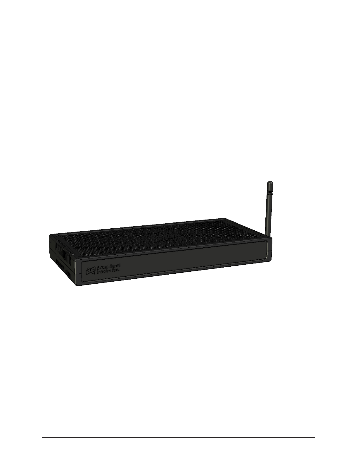
The STB-4000 is a high-performance set-top box for hospitality applications. The STB-4000 provides digital
content delivery, streaming video, TV control, wireless operation, and several other features in a compact,
lightweight enclosure that can be mounted in a variety of locations.
This guide covers the following models:
• STB-4000
STB-4000 User Guide
1-1
Page 6
Chapter 1 Features, Specications, and Safety Information
Unit Features
• Wireless Connectivity — The STB-4000 wireless option offers 802.11 wireless connectivity to
wireless network access points in hotels.
• USB — Two USB ports for connecting USB devices.
• HDMI — Two standard HDMI output ports for connecting audio/video to TV displays. One port is
dedicated to Chromecast A/V.
• Ethernet — Ethernet port for connecting to the hotel network.
• IR Input/Output — IR input/output ports for controlling non-hospitality TVs.
• Digital Audio — Digital optical port for connecting digital audio to AV receivers.
• MPI — MPI port for connecting to TVs with MPI interfaces.
1-2
STB-4000 Set-Top Box
STB-4000 User Guide
Page 7
Chapter 1 Features, Specications, and Safety Information
Rear Panel Connections
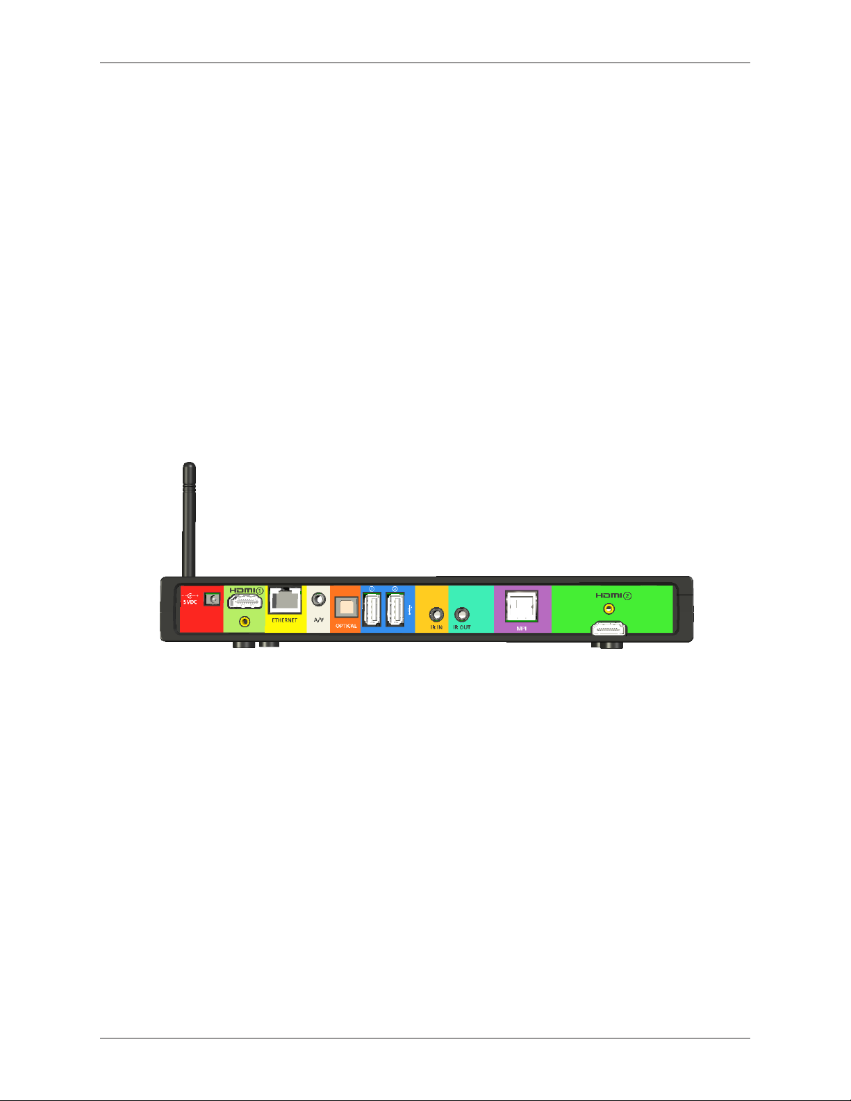
The rear-panel connections shown below include (from left to right):
• DC power input for 5V DC external power supply
• HDMI port for connecting A/V to TV HDMI input
• Ethernet port for connecting to the hotel network
• 3.5mm A/V port for connecting analog audio/video to TV
• Optical port for connecting digital audio/video to a receiver or amplier
• 2 USB ports for connecting USB devices
• IR input and output ports for IR devices
• MPI Adapter port for connecting to hospitality TV MPI port
• HDMI port for connecting Chromecast A/V to TV HDMI input
DC Power Input
The rear-panel 5V DC power input accepts the barrel-plug end of the 5-volt DC external power supply
required for use.
HDMI Output
The left-side rear-panel HDMI port accepts an HDMI cable for connecting audio and video to a standard
TV HDMI input.
Ethernet Port
The rear-panel Ethernet port accepts an Ethernet cable for connecting the STB-4000 to the hotel network.
A/V Analog Output
The rear panel includes a 3.5mm A/V port for connecting analog audio/video to TV.
STB-4000 User Guide
1-3
Page 8

Chapter 1 Features, Specications, and Safety Information
Optical Audio Output
The rear-panel Optical Audio output port on the rear panel accepts a TOSLINK optical cable for
connecting digital audio to a receiver or amplier.
USB Ports
Two rear-panel USB ports accept a USB cable for connecting external USB devices.
IR Input/Output Ports
The IR Input/Output ports are to be used for non-hospitality TVs which do not have an MPI port. These
ports allow the STB-4000 to communicate with non-hospitality TVs using IR commands and the TV’s builtin IR receiver.
The rear-panel IR Input port accepts an IR Receiver cable for receiving IR from a Remote Control when
the STB-4000 is not placed in line of sight of the remote. The IR output port accepts an IR Transmitter
cable for TVs which do not have MPI ports. The IR Transmitter is located close to the IR Receiver on the
TV so that the STB-4000 can transmit IR commands directly to the TV via IR.
MPI Port
The rear-panel MPI port accepts a cable for connecting to a room TV’s serial MPI control port.
HDMI Output for Streaming TV
The right-side rear-panel HDMI port accepts an HDMI cable for connecting audio and video to a TV
HDMI input. This port is dedicated to streaming video/audio using an internally mounted device such as
Chromecast.
Care and Maintenance
Taking simple precautions and observing guidelines for care and maintenance will help ensure that the
STB-4000 remains in good operating condition.
Protection from Impact
Make sure to place the unit in an area where there is little chance of direct impacts from objects.
Cleaning
The surfaces of the cabinet and the front-panel should be cleaned periodically with a soft, lint-free cloth to
remove ngerprints, oils, and dirt.
1-4
STB-4000 User Guide
Page 9

Chapter 1 Features, Specications, and Safety Information
Technical Specications
The following are specications for the STB-4000 Set-Top Box (specications subject to change):
Dimensions
• 7.75 inches (W) x 1.71 inches (H) x 6.00 inches (D)
Weight
• 1 lb
Rear Panel Connections
• Power supply — Maximum 5V DC @ 3amps
• 2 HDMI outputs — 1 standard HDMI port for connecting HDTV audio/video to TV and 1 standard
HDMI port for Chromecast HDTV audio/video to TV
• Ethernet — 10/100/1000 Mb/sec (1 RJ45 port)
• A/V output — 3.5mm CVBS A/V analog output
• Optical — For connecting standard optical digital audio devices
• USB 2.0 — Two USB 2.0 ports for connecting USB devices
• IR Input/Output — 3.5mm ports for connecting to non-hospitality TVs.
• MPI port — RJ12 port for connecting to MPI input of Hotel TV
Internal Features
• GPU — 8-core 450MHz
• RAM — 2 Gbytes internal RAM
• Flash — 16 Gbytes FLASH
• Wireless — 802.11 a/b/g/n/ac
Power Requirements
• 5V DC 3-Amp external power supply.
Power Consumption
• Average: 6 watts
Minimum Wiring Requirements
• CAT5e cable for LAN connections
• Shielded HDMI cables for connection to TV
STB-4000 User Guide
1-5
Page 10

Chapter 1 Features, Specications, and Safety Information
Important Safety Information
This section covers important safety information you should know before installing and using the
STB-4000 Set-Top Box.
Safety Instructions
The STB-4000 is designed and tested to meet the latest standards for safety. However, to ensure safe
use it is important to follow the safety instructions marked on the product and included in this manual to
help guard against personal injury and/or damage to the unit:
• Read and keep these instructions. Heed all warnings and follow all instructions.
• Do not use this unit near water or a heat source such as a radiator or heat duct. The unit should
not be operated in high-temperature or high-humidity environments.
• Refer all servicing to qualied service personnel. Servicing is required when the unit has been
damaged in any way, the power-supply cord or plug is damaged, liquid has been spilled into or
objects have fallen into the unit, or the unit has been exposed to rain or moisture, does not operate
normally, or has been dropped. If any of these conditions occur, unplug the unit from the power
source and refer servicing to qualied personnel.
• Never pull on the power cord. Disconnect the unit from DC power by removing the power plug from
the rear panel power input. Install the unit near an outlet that you can easily reach.
• This equipment is designed for 5V DC operation only. This unit should be operated only from the
type of power source indicated in the Technical Specications section of this guide. Connection to
any other power source will void the warranty.
• The front panel is susceptible to damage from impact. Locate the unit in an area where the
chance of direct impacts from objects is minimized. Take precautions to reduce the risk of objects
hitting the front panel.
1-6
STB-4000 User Guide
Page 11

Chapter 1 Features, Specications, and Safety Information
Regulatory Information
Federal Communications Commission (FCC) Notice (U.S. Only)
NOTICE: This equipment has been tested and found to comply with the limits for a Class B digital
device, pursuant to Part 15 Subpart C of the FCC Rules. These limits are designed to provide
reasonable protection against harmful interference in a commercial and residential installation.
This equipment generates, uses, and can radiate radio frequency energy and, if not installed
and used in accordance with the instructions, may cause harmful interference to radio
communications. However, there is no guarantee that interference will not occur in a particular
installation. If this equipment causes harmful interference to radio or television reception, which
can be determined by turning the equipment off and on, the user is encouraged to try to correct
the interference by one or more of the following measures:
• Reorient or relocate the receiving antenna.
• Increase the separation between the equipment and receiver.
• Connect the equipment into an outlet on a circuit different from that to which the receiver is
connected.
• Consult the dealer or an experienced radio/TV/data technician for help.
This device complies with Part 15, Subpart C of the FCC rules and with RSS-210 of Industry
Canada. Operation is subject to the following two conditions:
(1) This device may not cause harmful interference.
(2) This device must accept any interference received, including interference that
may cause undesired operation.
Le présent appareil est conforme aux CNR d’Industrie Canada applicables aux appareils radio
exempts de licence. L’exploitation est autorisée aux deux conditions suivantes:
(1) l’appareil ne doit pas produire de brouillage, et
(2) l’utilisateur de l’appareil doit accepter tout brouillage radioélectrique subi,
même si le brouillage est susceptible d’en compromettre le onctionnement.
NOTICE: Changes or modications made to this equipment not expressly approved by
Exceptional Innovation may void the FCC authorization to operate this equipment.
NOTICE: THIS INFORMATION TECHNOLOGY EQUIPMENT CONFORMS TO UL STD 60950-1 AND
IS CERTIFIED TO CSA STD C22.2 NO. 60950-1.
Radiofrequency Radiation Exposure Information:
This equipment complies with FCC radiation exposure limits set forth for an uncontrolled
environment. This equipment should be installed and operated with minimum distance of 20 cm
between the radiator and your body.
This transmitter must not be co-located or operating in conjunction with any other antenna or
transmitter.
STB-4000 User Guide
1-7
Page 12
Chapter 1 Features, Specications, and Safety Information
For body-worn operation, this unit has been tested and meets the FCC RF exposure guidelines
when used with the Exceptional Innovation accessories supplied or designated for this product.
Use of other accessories may not ensure compliance with FCC RF exposure guidelines.
Warnings
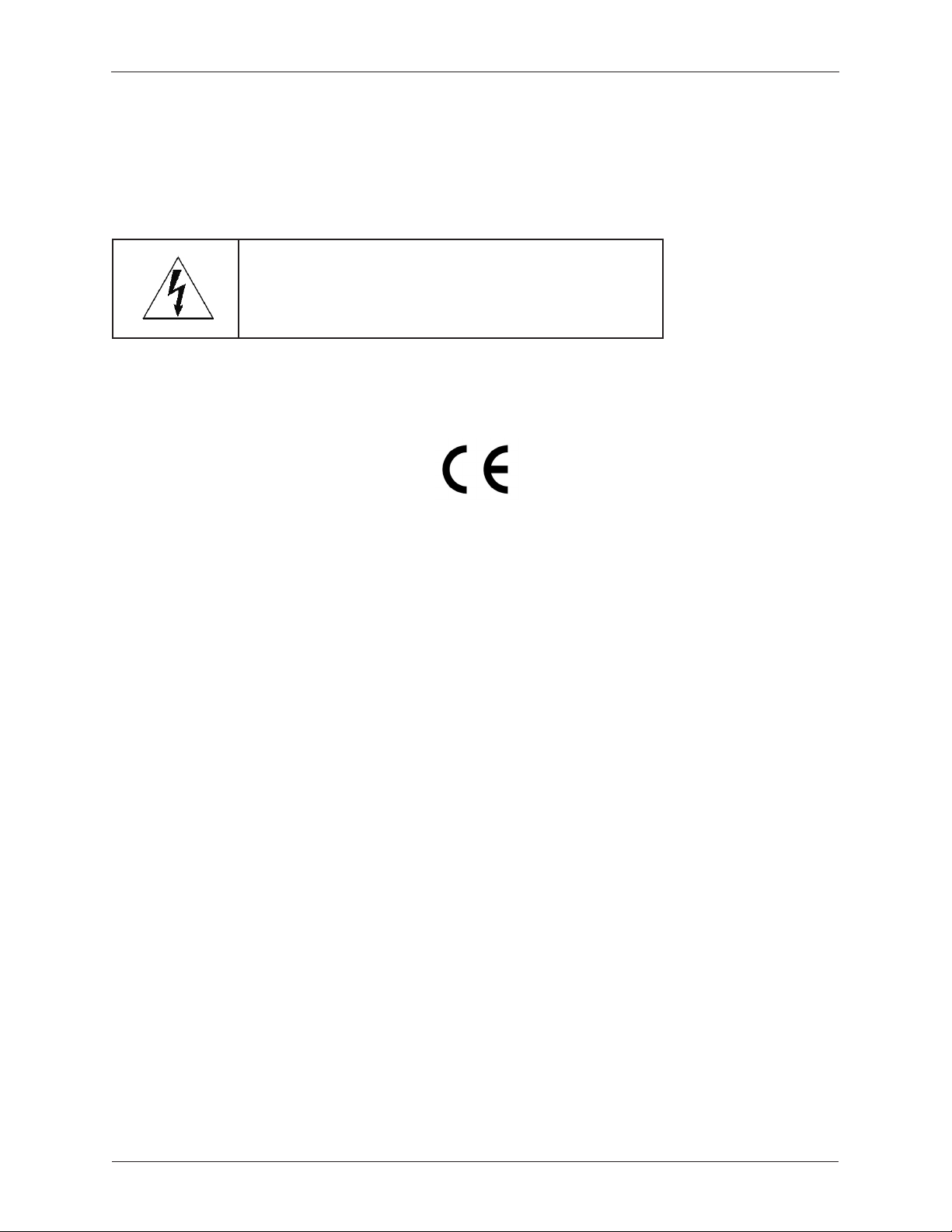
The lightning ash with arrowhead symbol, within an
equilateral triangle, is intended to alert the user to the
presence of uninsulated “dangerous voltage” within the
product’s enclosure that may be of sufcient magnitude
to constitute a risk of electric shock to persons.
The device bearing the trade name and model specied above has been shown to comply with
the applicable technical standards as indicated in the measurement report and was tested in
accordance with the measurement procedures specied in European Council Directive - EMC
Directive 2004/108/EC. The device passed the test performed according to:
Standards:
EN 55022: 2010 and CISPR 22: 2008 (modied)
1-8
STB-4000 User Guide
Page 13

Chapter 2 Installation and Setup
Installation and Setup
Overview
This chapter describes how to install and set up an STB-4000 Set-Top Box.
Items Included with the STB-4000
Check to make sure the following items are included in the shipping carton:
• STB-4000 unit
• International auto-switching AC/DC Power Supply
Items Included in the STB-4000 Cable Kit
• Cat5e Ethernet LAN Cable
• 2 HDMI Cables
Chapter
2
• 2 MPI Cables (for LG and Samsung Hospitality TVs)
• A/V Cable
Items Required for Installation
The following are required for installation:
• RJ45-terminated LAN network cable for connecting the unit to the hotel network. A Cat5e LAN Cable
is included in STB-4000 Cable Kit.
• Working network connection (Ethernet)
• HDMI Cable for A/V connection to TV. (2 HDMI Cables included in STB-4000 Cable Kit).
• MPI cable for communication with hospitality TV. (2 MPI Cables included in STB-4000 Cable Kit).
Optional Items for Installation
• A/V Cable for connection to A/V Receiver or TV. (A/V Cable included in STB-4000 Cable Kit).
• Digital Optical TOSLINK Cable for connecting digital audio to AV Receiver (NOT INCLUDED).
• IR Cables for communication with non-hospitality TVs (NOT INCLUDED).
STB-4000 User Guide
2-1
Page 14
Chapter 2 Installation and Setup
Install an STB-4000
This section covers the steps to install an STB-4000 Set-Top Box before putting it into service:
1. Connecting the STB-4000 to the network
2. Connecting the STB-4000 to the TV
3. Connecting the STB-4000 to Power
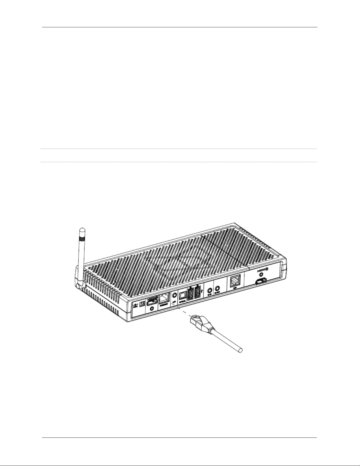
Connect the STB-4000 to the network
Perform the following steps to connect the STB-4000 to the network. When you have completed these
steps, go to the next section.
Note: Use cabling long enough to avoid placing stress on the input or output connections.
1. Place the unit close to a network connection.
2. Connect one end of a LAN cable to the network connector on the wall, router, or hub device.
3. Connect the other end to the Ethernet port on the rear panel as shown below:
4. Continue to the next section.
2-2
STB-4000 User Guide
Page 15
Chapter 2 Installation and Setup
Connect the STB-4000 to the TV
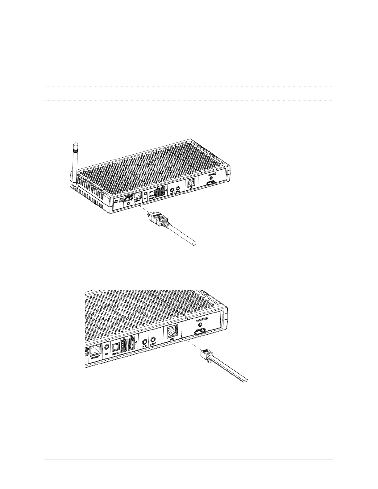
Perform the following steps to connect the STB-4000 to the TV using the HDMI and MPI ports. When you
have completed these steps, go to the next section.
Note: Use cabling long enough to avoid placing stress on the input or output connections.
1. Connect one end of the HDMI cable to the HDMI port on the STB-4000 rear panel as shown below.
2. Connect the other end of the HDMI cable to the HDMI port on the TV.
3. Connect the end of the MPI cable labeled STB to the MPI port on the rear panel as shown below.
4. Connect the end of the MPI cable labeled TV to the MPI port on the back of the TV.
5. Continue to the next section.
STB-4000 User Guide
2-3
Page 16
Chapter 2 Installation and Setup
Connect the STB-4000 to Power
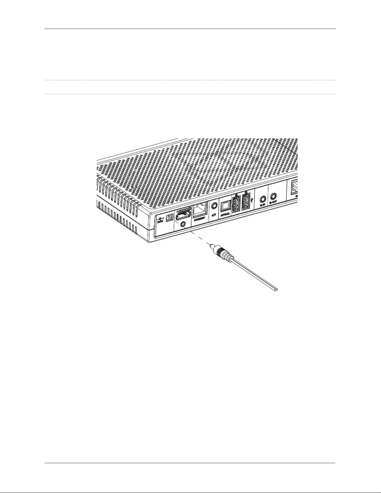
Perform the following steps to connect the STB-4000 to the 5V DC power supply.
Note: Use cabling long enough to avoid placing stress on the input or output connections.
1. Connect the 5V DC supply to the wall outlet.
2. Connect the DC supply barrel plug to the power input on the left side of the STB-4000’s rear panel as
shown below:
3. Wait for the unit to go through its boot process. This can take up to 3 minutes to complete. When the
boot process completes, you will see a splash screen on the TV.
Note: If this screen does NOT appear, unplug power, wait 5 seconds and plug it back in. If the unit
does not show the splash screen after 3 minutes, call Support at 1-888-860-6090.
4. Continue to the next section.
2-4
STB-4000 User Guide
Page 17

Chapter 2 Installation and Setup
Set Up an STB-4000
Once you have connected the STB-4000 to the network, TV, and power, you need to perform the setup
procedure.
Note: Setup typically takes from 5 to 10 minutes to complete, depending on updates.
Perform the following steps to set up the STB-4000.
Set Up Steps Go Here
Continue to the next section.
STB-4000 User Guide
2-5
Page 18
Chapter 2 Installation and Setup
Other Rear Panel Connections
This section covers other rear panel connections for the STB-4000, including:
• A/V connection to an TV/Amp/Receiver
• Optical Audio connection to a TV/Amp/Receiver
• USB connection from/to USB devices
• IR input/output connections for non-hospitality TVs
• HDMI connection for streaming TV via Chromecast (requires Chromecast media device)
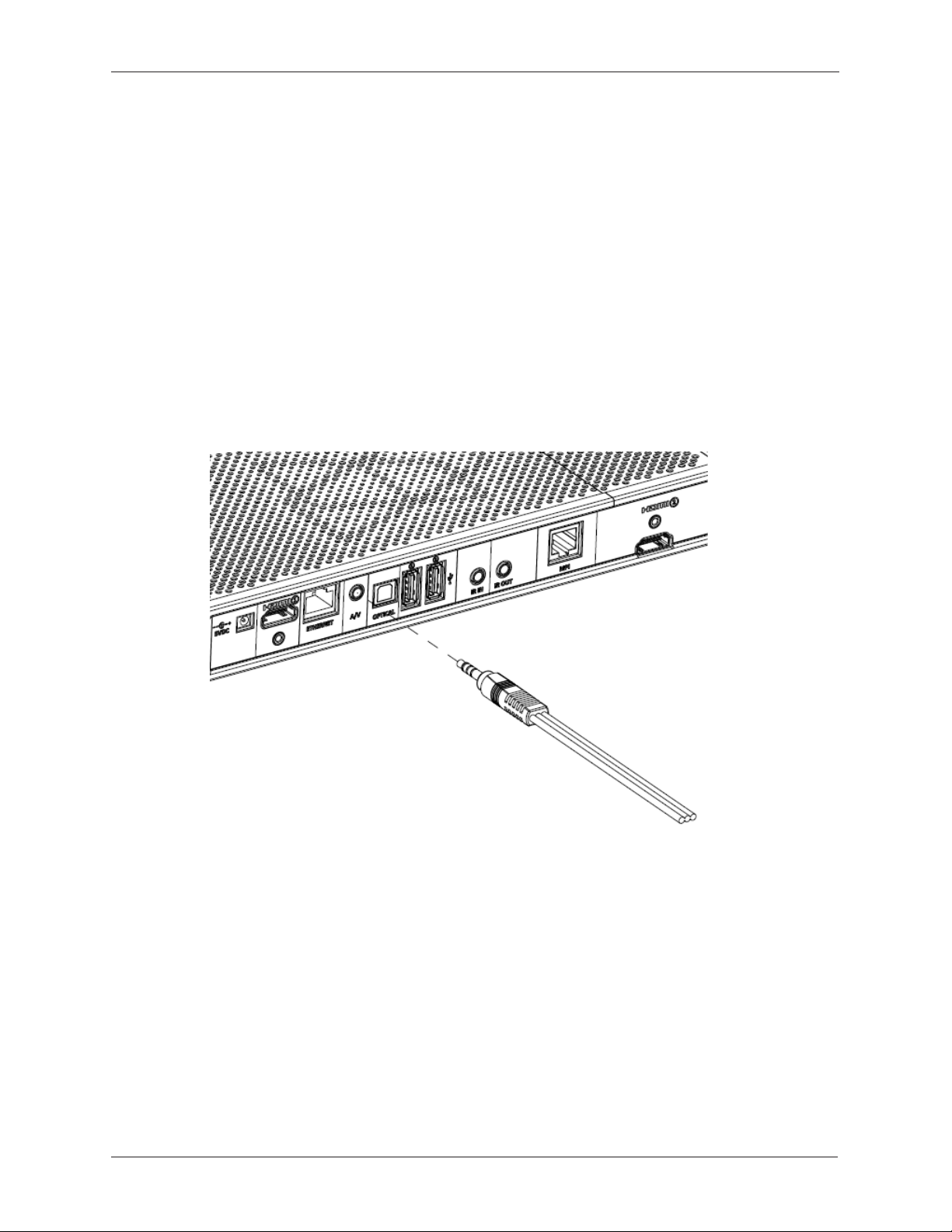
A/V Connection to TV, Amp, or Receiver
1. Connect the 3.5mm analog AV (4-conductor) cable to the AV port on the left side of the rear panel.
2. Connect the red and white RCA plugs on the other end to the audio input on the TV/Amp/Receiver.
3. Connect the yellow RCA plug on the other end to the video input on the TV/Amp/Receiver.
2-6
STB-4000 User Guide
Page 19
Chapter 2 Installation and Setup
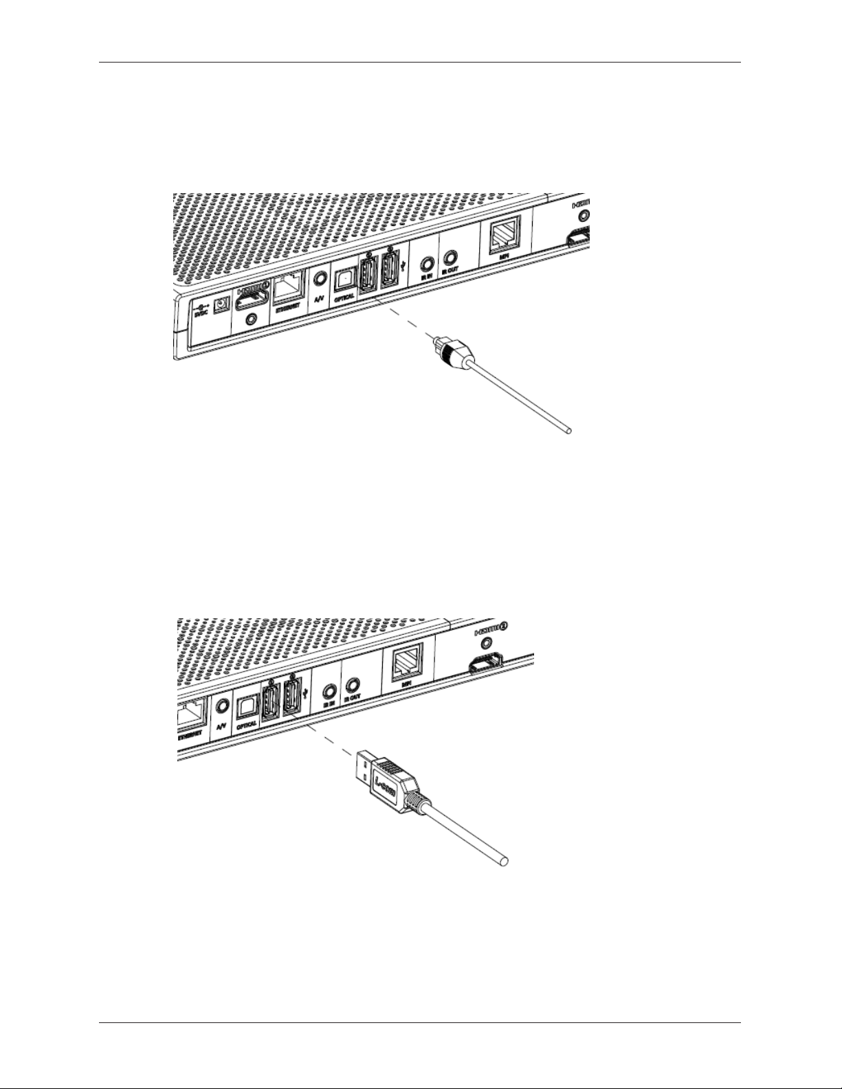
Optical Audio Connection to TV, Amp, or Receiver
1. Connect an optical cable to the Optical audio port on the left side of the rear panel.
2. Connect the other end of the optical cable to the TV/Amp/Receiver.
Connection to USB Devices
1. Connect a USB Type A cable to either USB port on the left side of the rear panel.
2. Connect the other end of the cable to the USB Device.
STB-4000 User Guide
2-7
Page 20
Chapter 2 Installation and Setup
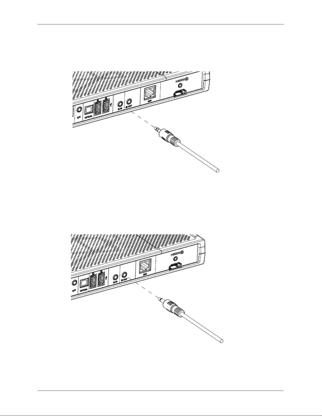
IR Input Connection
1. Connect the 3.5mm plug of an IR receiver cable to the IR IN port on the rear panel.
2. Place the bulb of the IR Receiver cable on the TV or in line of sight of the Remote control.
IR Output Connection
1. Connect the 3.5mm plug of an IR Transmitter cable to the IR OUT port on the rear panel.
2. Place the bulb of the IR Transmitter cable near the IR Receiver on the TV/Amp/Receiver to be
controlled.
2-8
STB-4000 User Guide
Page 21
Chapter 2 Installation and Setup
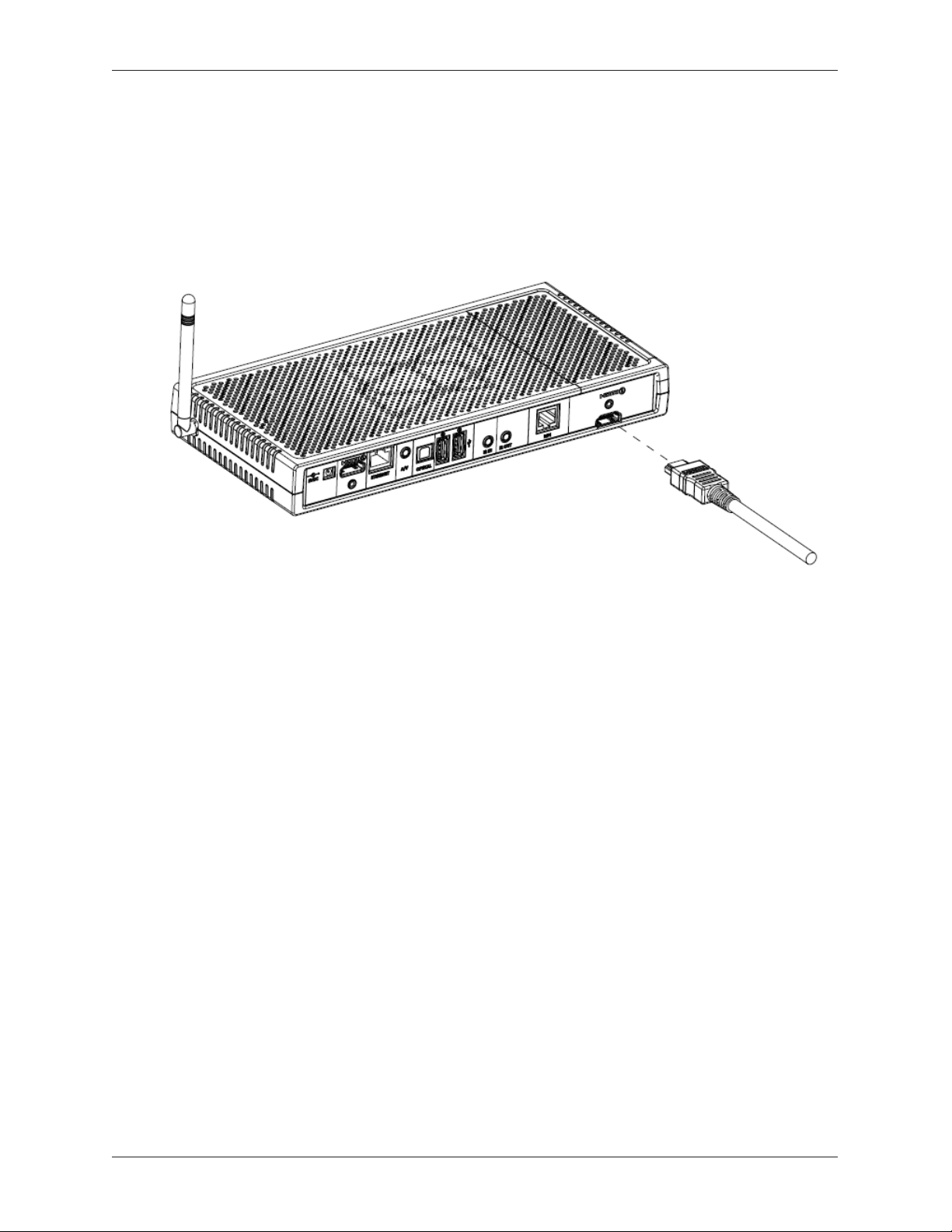
HDMI Chromecast Connection to TV
The HDMI connection for Chromecast requires that the Chromecast media device be installed inside the
STB-4000 chassis.
1. Connect an HDMI cable to the HDMI port on the right side of the rear panel.
2. Connect the other end of the HDMI cable to the HDMI input on the TV.
STB-4000 User Guide
2-9
Page 22

Chapter 2 Installation and Setup
2-10
STB-4000 User Guide
Page 23

Chapter 3 Troubleshooting
Chapter
3
Troubleshooting and Maintenance
Overview
This chapter discusses the information you can use to troubleshoot the STB-4000 Set-Top Box in case of
problems. It also covers procedures for replacing the hard drive, returning the unit, and contacting Product
Support. Read the following sections to learn more about troubleshooting methods and procedures and how
to get assistance:
• Troubleshooting Chart
• Returning Equipment for Repair or Replacement
• Website and Helpline
STB-4000 User Guide
3-1
Page 24

Chapter 3 Troubleshooting
Troubleshooting Chart
The STB-4000 Set-Top Box is designed to provide years of trouble-free service. However, if problems
arise with the unit’s hardware or software, you can use this troubleshooting chart to help isolate the cause
of the trouble and in many cases correct it.
Note: When following the steps is unsuccessful in clearing a problem and the chart recommends that you
contact support, the number to call is 1-877-890-6090.
Important:
• These troubleshooting procedures assume that the Network connection and Power to the unit have
been tested and are working as they should.
• The procedures in this chart cover possible hardware and software issues based on the symptoms
they may cause. In many cases, if the cabling connections have been veried and power-cycling the
unit does not correct the problem, it should be replaced.
Problem Solution
The STB-4000 will not
turn ON (no response).
• Make sure the 5-volt supply is connected to the AC power source
and is providing the correct voltage. Make sure the DC power plug is
connected to the DC power input on the rear panel.
• Unplug the Power plug, wait 5 seconds, and plug it back in. Wait three
minutes for the unit to complete its boot process.
• If the problem persists, replace the unit or contact support.
The unit is ON but not
communicating with
the network (does not
respond to commands).
No Display On TV • Check Power to STB-4000
No Communication with TV• Check MPI Cable from MPI Port to TV MPI Port
• Make sure the LAN cable plug is inserted all the way into the Ethernet
port on the rear panel. Make sure the other end of the LAN cable is
plugged all the way into the network port on the wall.
• Make sure that the RJ45 plugs on both ends of the LAN cable are
terminated correctly.
• Unplug the Power plug, wait 5 seconds, and plug it back in. Wait three
minutes for the unit to complete its boot process.
• If the problem persists, replace the unit or contact support.
• Verify that the STB-4000 is ON.
• Check HDMI Cables from the STB-4000 HDMI outputs to the TV.
• Check IR In/Out cables for non-hospitality TVs
3-2
STB-4000 User Guide
Page 25

Chapter 3 Troubleshooting
Website and Helpline
You can visit the website at www.exceptionalinnovation.com to learn more about our products.
If you have questions about your STB-4000, contact our Product Support Helpline at:
1-877-890-6090
Please read this User Guide carefully before contacting us. When you call our helpline, make sure your
hardware product is at hand so that technical support can more quickly help you correct the problem.
STB-4000 User Guide
3-3
Page 26

Chapter 3 Troubleshooting
3-4
STB-4000 User Guide
Page 27

Chapter 4 Warranty and Return Information
Chapter
4
Warranty and Returns
Overview
This chapter covers important Warranty and Return information for the STB-4000. You should read this
information carefully before placing the STB-4000 into service or attempting to return it for repair or
replacement.
Warranty
The STB-4000 warranty is 1 year for parts, 90 days for labor, effective from the date of shipment from
the manufacturer. For detailed warranty and return information, refer to Returning Equipment for Repair/
Replacement in this chapter.
Returning Equipment for Repair or Replacement
Warranty Service
The hardware product warranty is 1 year for parts, 90 days for labor, effective from the date of shipment from
the manufacturer. To qualify for warranty service, returns must also meet the following criteria:
• Products must be in the original manufacturer’s packaging and shipped securely.
• Products must be complete with any standard certication labels (UL listing, capacity, brand name, UPC
code) originally placed and not tampered with.
• Product serial number, or any similar identication numbers, must match the serial number on the
package or invoice.
• Products must be free from damage of any type, including, but not limited to dents, scratches, cracks,
abuse, defacement or indication of removed screws/fasteners or seals.
• Products so labeled with a security seal must have the seal intact and not be tampered with.
Important: Returned items may be subject to charges and fees based on the following criteria:
• If an item is submitted with an RMA number but during diagnosis is determined to be damaged or
otherwise outside of warranty, Product Support will provide notication of such and a diagnostic bench
fee of $65 will be charged to determine the extent of damages and/or repairs needed.
• Items that are returned without an RMA number will be rejected or subject to a restocking fee at Product
Support’s discretion.
STB-4000 User Guide
4-1
Page 28

Chapter 4 Warranty and Return Information
Returns
If you need to return a hardware product for repair or replacement, follow the steps listed here:
1. Contact Product Support at 1-877-890-6090 and supply the serial number and the nature of the
problem with the defective unit so that the serial number and defect information can be logged.
Product Support will then provide instructions and issue an RMA number.
2. Pack the equipment in its original packaging (or other suitable packaging) with the accessories.
Include any paperwork that may have the RMA number inside this box.
3. Pack the box securely inside an outer box packed with packing peanuts or bubble wrap.
4. Clearly write the RMA number on the outside of the carton. Cover the number with clear shipping
tape to protect it during shipping.
5. Ship the box back to this address:
Exceptional Innovation Inc.
ATTN: RMA Department
480 Olde Worthington Road
Suite 350
Westerville, OH 43082
Product Support will coordinate receipt of the returned goods and shipment of the repaired or
replacement product.
Note: For instances where the MAC ID of a unit changes due to a repair, Product Support will notify the
customer of the new MAC address.
Repairs
Note: Returned products that qualify for repair will either be repaired or replaced.
The following criteria cover the cost of repairs:
• An estimate of parts and labor costs for repair will be provided to the customer by Product Support.
• The customer can accept or decline the repairs. If accepted, the item will be repaired and returned as
per the estimate.
• If declined, Product Support will ship the damaged item back to the customer at the customer’s
expense.
For more detailed information on Warranty, Service, Returns, Repairs and Replacements, visit:
www.exceptionalinnovation.com/support.html
4-2
STB-4000 User Guide
Page 29

FCC Radiation Exposure Statement
The antennas used for this transmitter must be installed to provide a separation distance of at
least 20cm from all persons and must not be co-located or operating in conjunction with any
other antenna or transmitter
 Loading...