

CUSTOMER MANUAL
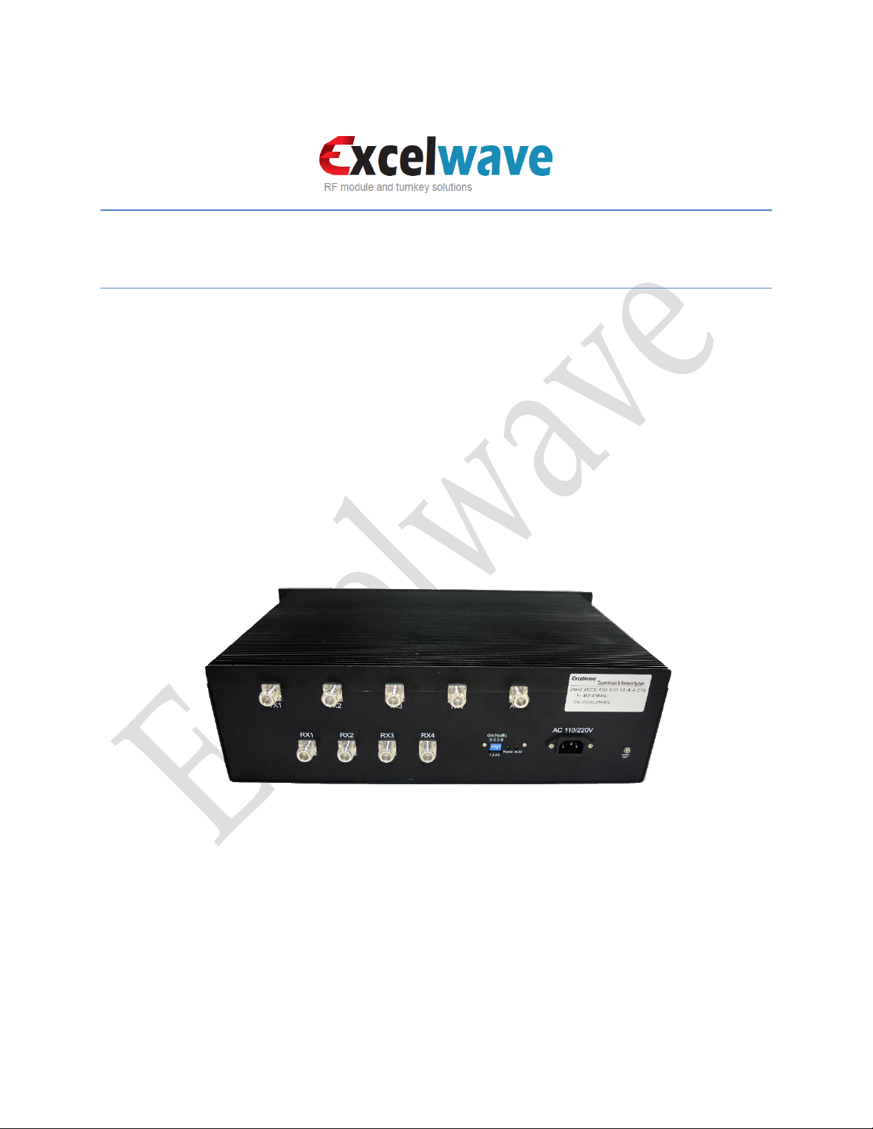
ECCS-450-470-4-4-1TB
450-470MHz Compact Combining System, 4
Channels, 50W, Duplexed, Field Tunable
DECEMBER 12, 2018
WWW.EXCELWAVE.COM
1-888-329-2878(Tel) 1-888-318-5528(Fax)
CM-ECCS-U441TB
Page 1 of 7
sales@excelwavetechnologies.com www.excelwavetechnologies.com 1-888-329-2878(Tel) 1-888-318-5528(Fax) Rev.2
©All rights reserved, 2018
PRODUCT DESCRIPTION
ECCS-450-470-50-4-4-1TB field tunable compact combining system allow four transmitters and four
receivers operating in 450-470MHz share one Tx/Rx antenna.
• Built-in tunable duplexer accessible by removing the cover on the bottom of the chassis.
• Tune the duplexer without disconnecting the interconnection cables.
• Gain adjustment switches on the rear panel.
Major Tuning Parameters
Typical Tuning Range
Tx Band
Low Band
Rx Band
High Band
Tx-Rx End-End Separation, Non-tunable
5MHz
Tx Tuning Range
450-470MHz
Tx Pass Bandwidth, Non-tunable
2MHz
Rx Tuning Range
450-470MHz
Rx Pass Bandwidth, Non-tunable
2MHz
Warning Message:
• Attempt to tune and operate the unit beyond the tuning range specified in the
above table may damage the unit and violate the warranty.
• Please follow the instruction to connect the network analyzer and tune the
duplexer.
Electrical Specifications
Typical Tuning Target
Insertion Loss (maximum): Tx-ANT Ports
8.2dB (including duplexer insertion loss)
Isolation (minimum): Tx-Rx Ports
85dB
Isolation (minimum): Tx-Tx Ports
75dB
Isolation (minimum): ANT-Tx Ports
55dB
VSWR @ Tx/Rx Ports
1.25:1
VSWR @ Antenna Port
1.4:1
CM-ECCS-U441TB
Page 2 of 7
sales@excelwavetechnologies.com www.excelwavetechnologies.com 1-888-329-2878(Tel) 1-888-318-5528(Fax) Rev.2
©All rights reserved, 2018
TUNING INSTRUCTION
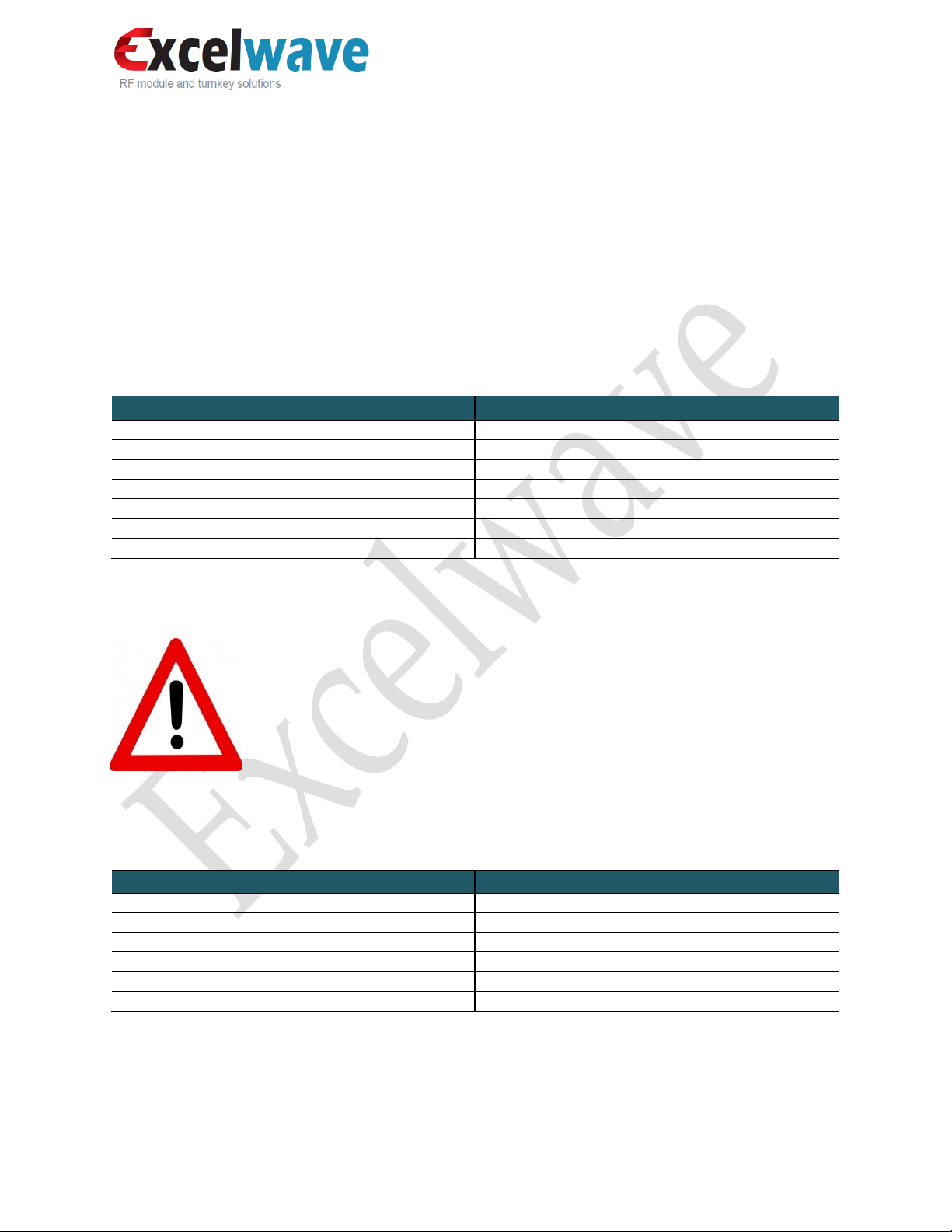
Tuning Tools
• L-shaped Tuning Socket Wrench (Supplied, as shown in the image)
• Screw Driver(Supplied)
• 2-Ports Vector Network Analyzer
(VNA)
Fig.1 Use of tuning screw driver and
wrench
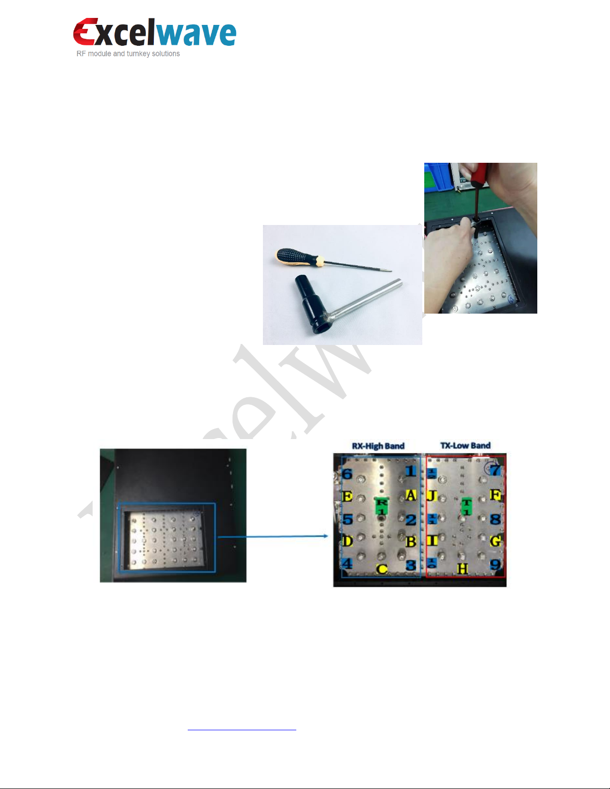
Tuning Rods
3 different type of tuning rods are identified in Fig.2 with digital numbers, letters and combinations of the
two, and colored in blue, yellow and green respectively.
Fig.2 Duplexer Tuning Rods
• Tuning Rods identified by digital numbers 1-6 in blue: High band Rx band adjustment
• Tuning Rods identified by digital numbers 7-12 in blue: Low band Tx band adjustment
• Tuning Rods identified by letters A-E in Yellow: High band Rx bandwidth adjustment
• Tuning Rods identified by letters F-J in Yellow: Low band Tx bandwidth adjustment
• Tuning Rods identified by R1 and T1 in Green: Rejection (Tx/Rx isolation) adjustment

CM-ECCS-U441TB
Page 3 of 7
sales@excelwavetechnologies.com www.excelwavetechnologies.com 1-888-329-2878(Tel) 1-888-318-5528(Fax) Rev.2
©All rights reserved, 2018
Network Analyzer Connection
Configuration and Connection for Rx Band Tuning
1. Connect VNA port1 to the product (ECCS) antenna port, and VNA port2 to ECCS port RX1, plug in
ECCS power supply, and terminate other Rx ports with 50 Ohm loads.
2. Set VNA output power to -20dBm and markers for the interested Rx and Tx frequency ranges.
3. Adjust the gain switches on the rear panel to set the gain (S21) to 0-2dB.
4. Move the Rx tuning rods to adjust the Rx frequency range and bandwidth following the instruction
given in the next section.
Fig.3 VNA Connection for Rx band tuning

CM-ECCS-U441TB
Page 4 of 7
sales@excelwavetechnologies.com www.excelwavetechnologies.com 1-888-329-2878(Tel) 1-888-318-5528(Fax) Rev.2
©All rights reserved, 2018
Gain switches
▪ Up-On
▪ Down-Off
When all gain switches are off, the maximum output gain
is 10±1dB. When a switch is on, the gain will drop
corresponding to the number indicated by the switch.
For example, if the 4dB switch is on, then the gain will be
10±1-4=6±1dB. When more than one switches are on,
the gain will drop corresponding to the summation of the
numbers indicated by the switches.
Fig.4 Gain adjustment
Configuration and Connection for Tx Band Tuning
1. Connect VNA port1 to ECCS antenna port, VNA port2 to ECCS Tx1, plug in ECCS power supply, and
terminate other ports with 50Ohm loads.
2. Set VNA output power to -20dBm and markers for the interested Rx and Tx frequency ranges.
3. Move the Tx tuning rods to adjust the Tx frequency range and bandwidth following the instruction
given in the next section.
Fig.5 VNA connection for Tx tuning

CM-ECCS-U441TB
Page 5 of 7
sales@excelwavetechnologies.com www.excelwavetechnologies.com 1-888-329-2878(Tel) 1-888-318-5528(Fax) Rev.2
©All rights reserved, 2018
Connection Check List
Measurement
VNA Connection and Configuration
Port1
Port2
Load
Measure
Output Power
Gain
ANT
RX1
TX
S21
-20dBm
VSWR(Rx1)
ANT
RX1
TX
S22
-20dBm
Out of Band Rejection (TX-RX)
ANT
RX1
TX
S21
-20dBm
Isolation (RX1-RX2)
RX2
RX1
ANT
S12
-20dBm
Insertion Loss (ANT-TX1)
ANT
TX1
RX
S12
VSWR (ANT)
ANT
TX1
RX
S11
VSWR (TX1)
ANT
TX1
RX
S22
Isolation (ANT-TX1)
ANT
TX1
RX
S21
Out of Band Rejection (RX-TX)
ANT
TX1
RX
S12
Tuning Procedure
1. Flip over the unit, put it on a flat rubberized surface.
2. Remove the 4 screws for the cover on the bottom of the unit as show in Fig.6
Fig.6 Remove the cover
3. Slightly loosen the nuts for tuning rods with the supplied socket wrench.

CM-ECCS-U441TB
Page 6 of 7
sales@excelwavetechnologies.com www.excelwavetechnologies.com 1-888-329-2878(Tel) 1-888-318-5528(Fax) Rev.2
©All rights reserved, 2018
4. Frequency band shift. Gently move up and down the tuning rods with the screw driver to shift
the band to desired new band then lock the nuts. Move the frequency tuning rods clockwise will
lower the frequency, move the frequency tuning rods counter clockwise will increase the
frequency. Move up and down the tuning rods smoothly and switch between each rod to maintain
the shape of the VNA plots, as the example shown in Fig,7.
Fig.7 An example of 5MHz frequency shift by tuning
Yellow-The original frequency band Green-The retuned frequency band
5. Bandwidth adjustment. The bandwidth is pre-set at factory and not tunable except minor
adjustable to compensate the effect of frequency band shift. Move the bandwidth tuning rods
clockwise will widen the bandwidth, while counter clockwise will narrow the bandwidth.
6. VSWR optimization. The tuning in step-2 and step-3 may affect the VSWR, which can be
compensated by the combined tuning between each rod. During the tuning process, if moving
down a tuning rod will increase the VSWR, then move up the tuning rod to improve the VSWR
and try to move other rods to achieve the attempted frequency shift or bandwidth adjustment.
7. Rejection. The Tx-Rx rejection is pre-set at factory and usually does not need tuning. In case it is
needed, tuning rods T1 or R1 can be used to optimize the rejection.
8. Verification. Inspect all the parameters and ensure all meet the specification. Ensure each tuning
rod screw is tightened and the performance is stable when pushing the tuning rods. Replace the
cover and lock it by the screws.

CM-ECCS-U441TB
Page 7 of 7
sales@excelwavetechnologies.com www.excelwavetechnologies.com 1-888-329-2878(Tel) 1-888-318-5528(Fax) Rev.2
©All rights reserved, 2018
Appendix: Sample Test Curves
Model Number: ECCS-450-470-4-4-1TB
Fig. 8 Tx band shifted from 450-452MHz shifted to 461-463MHz
Fig. 98 Rx band shifted from 457-459MHz to 468-470MHz
 Loading...