

Excelsys XS Series, XS1000-24N-000, XS500-24N-000, XS500-36N-000, XS1000-36N-000 Instruction Manual
...
Doc. No: 40109r05 XS500/XS1000 Instruction Manual Excelsys Technologies Ltd
PLEASE READ THIS INSTRUCTION MANUAL CAREFULLY BEFORE
INSTALLATION OR USE OF THIS PRODUCT, AND KEEP IT IN A
SAFE PLACE FOR FUTURE REFERENCE. FOLLOW ALL WARNINGS
AND INSTRUCTIONS MARKED ON THE PRODUCT.
HIGH VOLTAGE WARNING!
Dangerous voltages are present within
these power supplies. These products
should only be worked on by qualified
personnel.
Instruction Manual
XS
1000-24N-000
24V
/42A
XS500-24N-000 24V/21A
XS1000-36N-000 36V/28A
XS500-36N-000 36V/14A
XS1000-48N-000 48V/21A
XS500-48N-000
48V
/10.5A
XS
Series products are designed for use within other equipmen
t or en
closures,
which restricts access to AUTHORISED COMPETENT PERSONNEL ONLY. The unit
covers are designed only to protect skilled personnel from hazards. They must not
be used as part of the external covers of any equipment where they may be
accessible to operators, since, under full load conditions, part or parts of the unit
may reach temperatures in excess of those considered safe for operator access.
The
XS series power supply should be supplied only by a power source of the type indicated on its label. The
unit should only be used with suitably rated
cables and appropriate connectors, sourced by the end user. If in doubt, contact Excelsys Applications Department for assistance. For installations in
accordance with EN60601-1, UL2601-1, the Neutral input supply lead must be provided with a suitable fuse protection device. See the Fuse table below
for details.
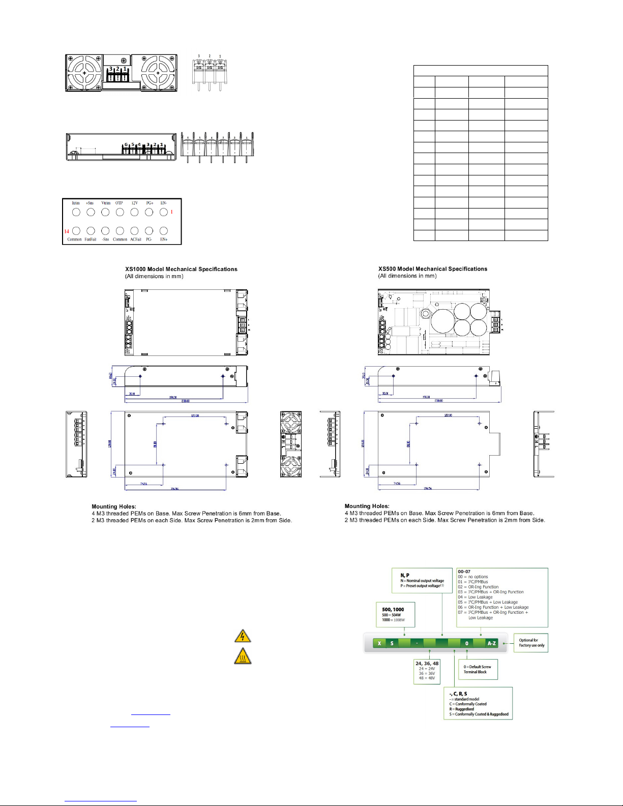
When securing the product, do not use screws which infringe the maximum penetration depth of 6mm for Base mounting and 2mm for Side mounting.
Customer fixings are provided on the base and side of the chassis. The XS1000 power supply models have integral fans and may be mounted in any
orientation provided that the air intake and air outlet areas are not impeded with particular regard paid to provide ventilation holes in any chassis on
which or near which the unit is mounted. For the XS500 models mounting instructions please contact Excelsys Applications Department for assistance.
AFTER DISCONNECTING THE AC SOURCE, ALLOW 4 MINUTES BEFORE DISASSEMBLY TO ALLOW CAPACITORS WITHIN THE UNIT TO DISCHARGE.
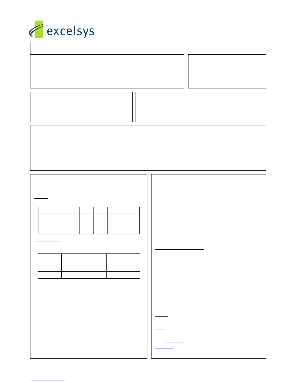
INPUT SPECIFICATIONS
Input Voltage Range: 100 to 240Volts AC
Input Frequency: 50/60Hz
Earth Leakage Current: 300µA – Standard Options 00,01,02,03
150µA - Low Leakage Options 04,05,06,07
Input Fusing
Warning! To protect against risk of Fire, replace only with same rating and type. Fuses must be
replaced by qualified service personnel only.
Model Reference Fuse
Rating
Type Voltage Size
XS1000-24,
XS1000-36 &
XS1000-48
FS1 12A F 250V 6.25X32mm
XS500-24,
XS500-36 &
XS500-48
FS1 8A F 250V 6.25X32mm
OUTPUT SPECIFICATIONS
See Output table below, with more detail in Designers’ Manual. Each Model may be adjusted over
the full voltage range shown in the table subject to not exceeding the maximum rated Voltage and
Power shown in the table
(1)
.
Model Vmin Vnom Vmax Imax Watts
XS1000-24 14 24 28 42 1008
XS500-24 14 24 28 21 504
XS1000-36 19 36 40 28 1008
XS500-36 19 36 40 14 504
XS1000-48 29 48 58 21 1008
XS500-48 29 48 58 10.5 504
SAFETY
The XS models when correctly installed in a limited access environment are designed to comply
with the following requirements:
EN60950, UL1950, CSA 22.2 No.234 and IEC61010
EN60601-1, UL2601-1 and CSA 22.2-601-1 and
EN61010
For current approval status, please contact Excelsys Sales. Equipment manufacturers must protect
service personnel against inadvertent contact with the output terminals.
ENVIRONMENTAL PARAMETERS
The products are designed for the following parameters:
• Pollution Degree 2
• Installation Category 2
• Class I
• For use as part of another piece of equipment such that unit is accessible to service engineers
only.
• Altitude: -155 metres to +3000 metres from sea level.
• Humidity: 10 to 95% non-condensing.
• Operating temperature -25°C to +70°C
• Derate at 1.67% per °C above 40°C and up to 70°C.
Approval Limitations
Use In North America
When this product is used on 180 to 253 Volts AC mains with no neutral, connect one live wire to
L (live) terminal and the other live wire to N (neutral) terminal on the input connector. For
installation in accordance with EN60601-1, UL2601-1 and IEC60950-1, UL60950-1 the wires
connected to the Neutral terminal must be provided with a suitable fuse protection device. See
Fuse Table.
The attachment plug shall be rated to a current not less than 125% of the rated current of the
equipment.
LEVELS OF INSULATION
Subject to the limitations above
Dielectric strength testing is carried out as follows:
• Primary mains circuits to chassis: 1500V AC
• Primary mains circuits to secondary: 4000V AC.
• Secondary to chassis: 1500V DC.
EARTH TERMINAL MARKING
IMPORTANT
If in the end use equipment the incoming mains cable earth wire connects directly to the "GND"
connection without being interrupted or junctioned on its way to that connection, then this
connection forms the main protective earth of the system.
To comply with IEC60950, EN60950, UL1950 requirements and to comply with EN60601-1,
UL2601-1, CSA22.2-601-1 requirements then this must be marked with the symbol defined in the
IEC417 No. 5019a. The customer should therefore affix an adhesive label which will pass the 15
Second rub test (IEC60950 section 1.7.15) showing the symbol here adjacent to the earth
connection. This symbol must only be used at the first interruption / connection of the incoming
earth wire.
HEALTH AND SAFETY AT WORK ACT (UK ONLY)
To protect service personnel and users and to comply with section 6 of the Health And Safety
Acts, a clearly visible label should be fitted warning that surfaces of these units may be hot and
must not be touched when the units are in operation.
RECEIPT AND UNPACKING
On receipt a unit should be unpacked carefully and checked for transit damage. If the unit is
damaged, do not apply power or install the unit. SEEK SPECIALIST ADVICE!
WARRANTY
Warranty conditions are contained in our standard terms and conditions. Contact your
authorised outlet for repair.
OPTIONS
Thermal Signals, Temperature Alarm & Fan Fail are Open Collector signal indicators.
Notes:
1. Contact sales@excelsys.com for details including MOQs on alternative preset output voltages.
2. A French translation of this Instruction Manual is also available; document number 40112. Contact
sales@excelsys.com for a copy of this.
XS Base
Models
Excelsys Technologies Limited,
27 Eastgate Drive,
Eastgate Business Park,
Little Island, Cork, Ireland
Doc. No: 40109r05 XS500/XS1000 Instruction Manual Excelsys Technologies Ltd
Connector Details
Pin Input Output Signal
1 L +Vo EN2 N +Vo EN+
3 E +Vo PG+
4 -Vo PG5 -Vo 12VDC
6 -Vo ACFail
7 OTP
8 Common
9 Vtrim
10 -Sns
11 +Sns
12 FanFail
13 Itrim
14 Common
XS Model Labels Contain:
Input Freq,
Input Voltage,
Fuse Rating,
Max Power Rating,
Serial Number,
Maximum Line Current under rated conditions.
Warning Symbol (Danger High Voltage)
Warning Symbol (Caution Hot Surface)
Model Configuration as defined by the diagram to the right of this
text.
Notes:
1. Contact
sales@excelsys.com for details including MOQs on alternative preset output voltages.
2. A French translation of this Instruction Manual is also available; document number 40112. Contact
sales@excelsys.com for a copy of this.
Input Connector J7
Output Connectors J10 & J12
Output Signal Connector J5
Connector: Barrier Terminal Block,
Vertical, 3 Position, Pitch 0.375in.
Manufacturer: Molex
Manufacturer P/N: 38720-750
Connector: 2x Barrier Term
inal Block,
Vertical, 3 Position, Pitch 0.325in.
Manufacturer: Tyco
Manufacturer P/N: 2-1437667-5
Connector: Header, Shrouded, Vertical,
2 x7 Contacts, Pitch 2.0mm
Manufacturer: Molex
Manufacturer P/N: 87831-1420
Part Numbering System
 Loading...