

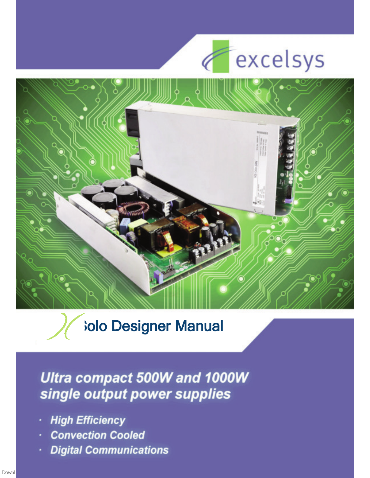
Solo Designer Manual
The Xsolo family of single output power supplies provides up to an incredible 1008W
in an extremely compact package.
Available in two package types, the high efficiency Xsolo delivers an incredible convection
cooled 504W in an open-frame U-channel form factor and up to 1008W in an enclosed, fan
cooled chassis.
The Xsolo platform comes with a host of features including: variable speed fan, 12V/300mA
isolated bias supply, remote ON/OFF, output voltage control and parallel operation for higher
power applications. Nominal output voltages are 24, 36V and 48V with wide adjustment
ranges and user defined set-points. Xsolo carries dual safety certification, EN60950 2
nd
Edition for Industrial Applications and EN60601-1 2ndand 3rdEdition for Medical
Applications, meeting the stringent creepage and clearance requirements, 4KVAC isolation
and <300uA leakage current. Xsolo is designed to meet MIL810G and is also compliant with
SEMI F47 for voltage dips and interruptions as well as being compliant with all relevant EMC
emission and immunity standards.
Optional features include I2C digital communications and OR-ing Function for N+1 redundancy.
The product can also be conformal coated and ruggedised for use in harsh environments. With
convection cooled power capability of over 500W, the Xsolo is ideal for use in a wide range of
applications: industrial, Hi-Rel MIL-COTS applications, as well as acoustically sensitive laboratory
and medical environments.
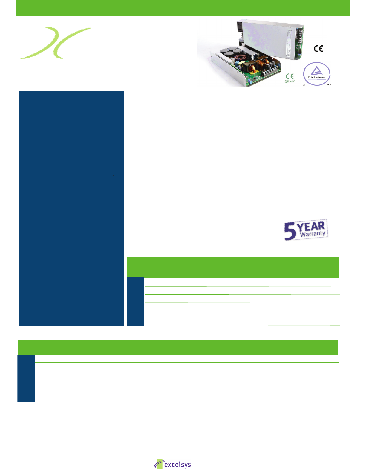
Single Output Power Supply 500W - 1000W
FEATURES
• Single output: 24V, 36V or 48V
• IEC60950 2
nd
Edition, IEC60601-1 2nd &
3rd Edition & IEC60601-1-2 4th Edition
EMC compliant
• Ultra high efficiency, >92%
• Low profile: 1U height (40mm)
• Convection Cooled 500W
• Fan Cooled 1000W (variable speed fan)
• 12V/300mA bias standby voltage
provided
• Remote ON/OFF Signal
• Power Good Signal
• MIL810G
• 2 MOPP
• SEMI F47 Compliant
• Suitable for Type B and BF rated
applications
• Optional I2C PMBus™Communications
• Optional OR-ing Function
• 5 Year Warranty
• Adjustable output voltage
• 5000m altitude for EN60950 applications
• All models feature active power factor
correction as standard
• Product Options: Conformal Coating,
Low Leakage Current and Ruggedised
APPLICATIONS INCLUDE
• Industrial
• Test & Measurement
• Medical
• Hi-Rel COTS
XS500-24 504 24 21.0 Yes Yes
XS1000-24 1008 24 42.0 Yes Yes
XS500-36 504 36 14.0 Yes Yes
XS1000-36 1008 36 28.0 Yes Yes
XS500-48 504 48 10.5 Yes Yes
XS1000-48 1008 48 21.0 Yes Yes
XS
Model Power Output Output Medical Approval Industrial Approval
(W) Voltage Current UL/EN60601-1 UL/EN60950
(A) 3rd edition 2nd edition
XS Models
Ultra-high efficiency 1U size
Model Vnom Power Description Set Point Dynamic Vtrim Imax Remote Power
(V) (W) Adjust Range (V) Range (V) (A) Sense Good
XS500-24 24 504 Convection Cooled U-Channel 19-28 14-28 21.0 Yes Yes
XS1000-24 24 1008 Enclosed Fan Cooled 19-28 14-28 42.0 Yes Yes
XS500-36 36 504 Convection Cooled U-Channel 26-40 20-40 14.0 Yes Yes
XS1000-36 36 1008 Enclosed Fan Cooled 26-40 20-40 28.0 Yes Yes
XS500-48 48 504 Convection Cooled U-Channel 36-58 29-58 10.5 Yes Yes
XS1000-48 48 1008 Enclosed Fan Cooled 36-58 29-58 21.0 Yes Yes
Xsolo
XS
* Full part numbering information including product options and ordering information on page 65.
solo
1
www.excelsys.com
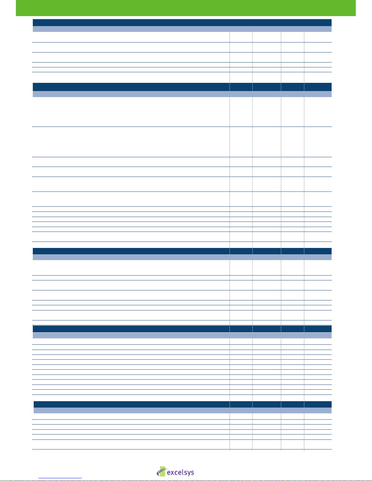
INPUT
Parameter Conditions/Decription Min Nom Max Units
Input Voltage Range Universal Input 47-440Hz 85 264 VAC
120 380 VDC
Power Rating XS500 504 W
XS1000 1008 W
Input Current XS500 5 A
XS1000 10 A
Inrush Current 230VAC @ 25°C 25 A
Undervoltage Lockout Shutdown 65 74 VAC
Fusing XS500 250VAC F8A HRC
XS1000 250VAC F12A HRC
OUTPUT
Parameter Conditions/Description Min Nom Max Units
Output Voltage Range XS500/1000-24: Multi-turn potentiometer 19 28 VDC
XS500/1000-24: Dynamic Vtrim range 14 28 VDC
XS500/1000-36: Multi-turn potentiometer 26 40 VDC
XS500/1000-36: Dynamic Vtrim range 20 40 VDC
XS500/1000-48: Multi-turn potentiometer 36 58 VDC
XS500/1000-48: Dynamic Vtrim range 29 58 VDC
Output Current Range XS500-24 21 A
XS1000-24 42 A
XS500-36 14 A
XS1000-36 28 A
XS500-48 10.5 A
XS1000-48 21 A
Load & Cross Regulation For 25% to 75% load change ±0.2 %
ORing Option ±0.4 %
Transient Response For 25% to 75% load change Voltage Deviation 2.5 %
Settling Time 500 µs
Ripple and Noise XS500/1000-24: 20MHz 240 mV pk-pk
XS500/1000-36: 20MHz 360 mV pk-pk
XS500/1000-48: 20MHz 480 mV pk-pk
Overvoltage Protection XS500/1000-24: Latching 33 34 37 VDC
XS500/1000-36: Latching 44 47 52 VDC
XS500/1000-48: Latching 61 63 69 VDC
Overcurrent Protection Straight line with hiccup activation at <30% of Vnom. 105 115 130 %
Line Regulation For ±10% change from nominal line ±0.5 %
Remote Sense 0.5 VDC
Overshoot 2 %
Rise Time Monotonic 3 5 ms
Turn-on Delay From AC in 500 800 ms
From Remote On/Off 10 ms
Hold-up Time For nominal output voltages at full load. 17 ms
GENERAL
Parameter Conditions/Description Min Nom Max Units
Isolation Voltage Input to Output 4000 VAC
Input to Chassis 1500 VAC
Output to Chassis 1500 VAC
Efficiency 230VAC, 1008W @ 24V/36V/48V >92 %
Safety Agency Approvals EN60601-1 2nd and 3rd Edition, cTUVus 60601-1
EN60950 2nd Edition, cTUVus 60950
Leakage Current 264VAC, 60Hz, 25°C 300 µA
264VAC, 60Hz, 25°C (Option 4) 150 µA
Signals See Page 3
Bias Supply Always on, current 300mA, 50mA XS500 12.0 VDC
Weight XS500 1.1 Kg
XS1000 1.3 Kg
MTBF Telecordia SR-332, 40°C ground benign, parts count. 550,000 Hours
EMC
Parameter Standard Level Units
Emissions
Conducted EN55011, EN55022, FCC Class B
Radiated EN55011, EN55022, FCC Class B
Harmonic Distortion EN61000-3-2 Class A Compliant
Flicker & Fluctuation EN61000-3-3 Compliant
Immunity
Electrostatic Discharge EN61000-4-2 Level 2
Radiated Immunity EN61000-4-3 Level 3
Fast Transients-Burst EN61000-4-4 Level 3
Input Line Surges EN61000-4-5 Level 3
Conducted Immunity EN61000-4-6 Level 3
Voltage Dips EN61000-4-11, SEMI F47 Compliant.
(1)
Compliant
ENVIRONMENTAL
Parameter Conditions/Description Min Nom Max Units
Operating Temperature -40 +70 °C
Storage Temperature -40 +85 °C
Derating See Page 62 for full temperature deratings
Relative Humidity Non-condensing 5 95 %RH
Shock and Vibration Designed to meet MIL810G
(2)
55 G
Altitude EN60601-1 Operational: 3000m, Storage 8000m 3000 m
EN60950 Operational: 5000m, Storage 8000m 5000 m
Single Output Power Supply 500W - 1000W
Xsolo
2
www.excelsys.com

Single Output Power Supply 500W - 1000W
Ultra-high efficiency 1U size
Xsolo
solo
XS1000-24N
Section 6.1
Overview of Xsolo
The Xsolo family of single output power supplies provides up to an incredible 1008W in an extremely compact package.
Available in two package types, the high efficiency Xsolo delivers an incredible convection cooled 504W in an open-frame
U-channel form factor and up to 1008W in an enclosed, fan cooled chassis.
The Xsolo platform comes with a host of features including: variable speed fan, 12V/300mA isolated bias supply, remote ON/OFF,
output voltage control and parallel operation for higher power applications. Nominal output voltages are 24V, 36V and 48V with wide
adjustment ranges and user defined set-points. Xsolo carries dual safety certification, EN60950 2nd Edition for Industrial
Applications and EN60601-1 2nd and 3rd Edition for Medical Applications, meeting the stringent creepage and clearance requirements, 4KVAC isolation and <300uA leakage current. Xsolo is designed to meet MIL810G and is also compliant with SEMI F47 for
voltage dips and interruptions as well as being compliant with all relevant EMC emission and immunity standards.
Optional features include I2C digital communications and OR-ing Function for N+1 redundancy. The product can also be conformal
coated and ruggedised for use in harsh environments. With convection cooled power capability of over 500W, the Xsolo is ideal for
use in a wide range of applications: industrial, Hi-Rel MIL-COTS applications, as well as acoustically sensitive laboratory and medical environments.
Section 6.2
Xsolo Features
EN60950 2nd Edition & EN60601-1 2nd and 3rd Edition•
MIL810G•
2 MOPP•
SEMI F47 Compliant•
Ultra high efficiency, >92%•
Low profile: 1U height (40mm)•
Convection Cooled 500W/Fan Cooled 1000W (variable speed fan)•
12V/300mA bias standby voltage provided•
Remote ON/OFF Signal, Power Good Signal•
5 Year Warranty•
Suitable for type B and BF rated applications•
Adjustable output voltage•
5000m altitude for EN60950 applications•
Product Options: Conformal Coating, Low Leakage Current,•
Ruggedised , PMBus, & OR-ing function
APPLICATIONS INCLUDE
Industrial•
Test & Measurement•
Medical•
Hi-Rel/MIL-COTS•
Communication•
www.excelsys.com
3

www.excelsys.com
Single Output Power Supply 500W - 1000W
Xsolo
Section 6.3
Installation Considerations
The Xsolo models may be mounted on any of three surfaces
using standard M3 screws. The chassis comes with four mounting points on the base. Maximum allowable torque is 2Nm. The
maximum penetration depth is 6mm. Maintain a 50mm minimum
clearance at both ends of the Xsolo power supply and route all
cables so airflow is not obstructed. The XS1000 unit draws air in
on the input side and exhausts air out the load side. If airflow ducting is used, avoid sharp turns that could create back pressure.
XS500 units are convection cooled. See Excelsys Application
Note: AN1504 on
website.
Avoid excessive bending of output power cables after they are
connected to the Xsolo powerMods. For high current outputs, use
cable-ties to support heavy cables and minimise mechanical
stress on output studs. Be careful not to short-out to neighbouring
output studs.
The maximum torque recommended on output connectors is
3Nm. Avoid applications in which the unit is exposed to excessive
shock or vibration that exceed the specified levels. In such applications, a shock absorption mounting design is required.
Section 6.4
Xsolo Control and Signals (Analog)
Voltage Adjustment
The Xsolo has been designed with maximum user flexibility as a
key objective. The output voltage can be adjusted over a wide
range by a number of methods.
Voltage adjustment and setting may be achieved by:
1. Voltage Setting via the on board potentiometer.
2. Remote voltage programming by applying a control voltage
(Vcontrol) between J5 Pin 9 (Vtrim) and J5 Pin 10 (-Sense)
3. Remote voltage programming by applying a resistor between
J5 Pin 9 (Vtrim) and J5 Pin 10 (-Sense).
An Excel spreadsheet has been developed to help users calculate output voltage and control values. These are available to
download from the support section of our website;
http://www.excelsys.com/technical-support/
XS500-24 and XS1000-24
By applying a control voltage (Vcontrol) between J5 Pin 9 (Vtrim)
and J5 Pin 10 (-Sense) the output voltage of XS1000-24 and
XS500-24 may be adjusted over a wide range. Vcontrol can be
read from the graph below or calculated with the formula:
Voutput = 12.59 x Vcontrol
Important: Vcontrol must not exceed 2.5V
Example.
Setting the output voltage to 20VDC via the Vtrim Pin
Voutput/12.59 = Vcontrol
20V/12.59 = 1.59V.
Vcontrol = 1.59V
See Graph for full range.
XS500-48 and XS1000-48
Using an external Voltage source (Vcontrol), the output voltage of
the XS1000-48 and XS500-48 may be adjusted over a wide
range.
By applying a control voltage (Vcontrol) between J5 Pin 9 (Vtrim)
and J5 Pin 10 (-Sense) the output voltage of XS1000-48 and
XS500-48 may be adjusted over a wide range. Vcontrol can be
read from the graph below or calculated with the formula
Voutput = 24.75 x Vcontrol
Important: Vcontrol must not exceed 2.5V
Example.
Setting the output voltage to 40VDC via the Vtrim Pin
Voutput/24.75 = Vcontrol
40V/24.75 = 1.62V.
Vcontrol = 1.62V
See Graph below for full range.
Remote voltage programming by an external resistor/potentiometer can also be implemented on the Xsolo. Simply apply
the appropriate resistor value between J5 Pin 9 (Vtrim) and J5
Pin 10 (-Sense). An Excel spreadsheet has been developed to
help users calculate output voltage and resistor values. These
are
available to download from the support section of our website;
http://www.excelsys.com/technical-support/
Current Limit Adjustment ( Voltage)
The Xsolo has been designed to allow users to adjust the onset
of Current Limit for reduced power or constant current applications. By applying a voltage (Vcontrol) between the Itrim pin, (J5
Pin 13), and -Vout, current limit of the Xsolo can be adjusted
from 0 A to the max rated current of the supply.
An Excel spreadsheet has been developed to help users calculate output current and control voltage values. These are available
to download from the support section of our website;
http://www.excelsys.com/technical-support/
4

Current Limit Adjustment on XS1000-48
By applying a control voltage (Vcontrol) between Itrim (J5, Pin 13)
and -Vout, current limit can be adjusted from 0-21A. Vcontrol can
be read from the graph below or calculated with the formula
Ioutput = 8.06 x Vcontrol
Important: Vcontrol should not exceed 3.0V for XS1000-48
Example.
Setting the output current limit of the XS1000-48 to 15A via the
Itrim Pin
Ioutput/8.06 = Vcontrol
15A/8.06 = 1.86VDC.
Vcontrol = 1.86VDC
See Graph for full range.
Current Limit Adjustment via Resistor/Potentiometer
The Xsolo has been designed to allow users to adjust the onset
of Current Limit by applying a resistor between the Itrim pin, (J5
Pin 13), and -Vout. An Excel spreadsheet has been developed
to help users calculate the appropriate resistor values to set output current. These are available to
download from the support section of our website;
http://www.excelsys.com/technical-support/
Current Limit Programming (Foldback)
The Current Limit characteristics of the Xsolo can be programmed to be either Straight Line or Foldback. The previous
sections refer to setting the Straight Line Current Limit of the
Xsolo. To implement Foldback Current Limit, an Excel spreadsheet has been developed to help users calculate the appropriate resistor values to define the onset and final current limit
points of the foldback current curve These are available to download from the support section of our website;
http://www.excelsys.com/technical-support/
Remote ON/OFF
The Xsolo may be inhibited by means of an appropriate signal
applied to an opto-isolated input (diode of an opto-isolater) on
pins J5 connector Pin 2 (positive) and Pin 1 (negative). The delay
from Inhibit to output turning OFF is typically <1ms.
Maximum current source allowed is 6.5mA.
Maximum applied voltage allowed is 13V.
Fan Fail
Fan Fail is an Open collector signal indicating that at least one of
the Xsolo fans has failed. This does not cause power supply
shutdown. The power supply will continue to operate for 10ms
after the temperature alarm signal is generated.
Current Limit Adjustment on XS500-24
By applying a control voltage (Vcontrol) between Itrim (J5, Pin 13)
and -Vout, current limit can be adjusted from 0-21A. Vcontrol can
be read from the graph below or calculated with the formula
Ioutput = 15.27 x Vcontrol
Important: Vcontrol should not exceed 1.5V for XS500-24
Example.
Setting the output current limit of the XS500-24 to 15A via the
Itrim Pin
Ioutput/15.267=Vcontrol
15A/15.267 = 0.98V.
Vcontrol = 0.98VDC
Current Limit Adjustment on XS1000-24
By applying a control voltage (Vcontrol) between Itrim (J5, Pin 13)
and -Vout, current limit can be adjusted from 0-42A. Vcontrol can
be read from the graph below or calculated with the formula
Ioutput = 15.267 x Vcontrol
Important: Vcontrol should not exceed 3.0V for XS1000-24
Example.
Setting the output current limit of the XS1000-24 to 30A via the
Itrim Pin
Ioutput/15.267=Vcontrol
30A/15.267 = 1.96VDC.
Vcontrol = 1.96VDC
See Graph for full range.
Current Limit Adjustment on XS500-48
By applying a control voltage (Vcontrol) between Itrim (J5, Pin 13)
and -Vout, current limit can be adjusted from 0-10.5A. Vcontrol
can be read from the graph below or calculated with the formula
Ioutput = 8.06 x Vcontrol
Important: Vcontrol should not exceed 1.5V for XS500-48
Example.
Setting the output current limit of the XS500-48 to 7.5A via the
Itrim Pin
Ioutput/8.06 = Vcontrol
7.5A/8.06 = 0.93V.
Vcontrol = 0.93VDC
www.excelsys.com
Single Output Power Supply 500W - 1000W
Xsolo
5

The Fan Fail signal is accessed via J5 connector Pin 12. There is
an on-board series current limit resistor of 2k connecting Pin 12 to
the collector of an NPN transistor opto-coupler output. The
emitter is connected to J5 Pin 8 – or Pin 14 (Common). When a
fan-fail condition is detected this transistor turns off.
Maximum current source allowed is 6.5mA.
Maximum applied voltage allowed is 13V.
AC Mains Fail
AC Mains fail signal is accessed through J5 connector Pin 6.
There is an on-board series current limit resistor of 2kohm
connecting Pin 6 to the collector of an NPN transistor optocoupler output. The emitter is connected to J5 Pin 8 or Pin 14
(Common).During normal operation the transistor is ON. When
input voltage is lost or goes below 80VAC the opto-transistor is
turned OFF at least 2 ms before loss of output regulation. (The
output voltage waveform above assumes a pull-up resistor to a
maximum voltage of +13V)
Maximum current source allowed is 6.5mA.
Maximum applied voltage allowed is 13V.
Over-Temperature Protection (OTP)
This is an opto-isolated open collector transistor signal
indicating that excessive temperature has been reached due to
fan failure or operation beyond ratings. This signal is activated
at least 10ms prior to system shutdown. The OTP signal is
accessed via J5 connector Pin 7. There is an on-board series
connect limit resistor of 2Kohm connecting Pin 7 to the collector
of an NPN transistor opto-coupler output.The emmitter is
connected to J5 Pin 8 or Pin 14 (Common).
The Fan Fail and Temp Alarm signal waveforms in the diagram
assume connection via a pull-up resistor to the 12 V bias source
or an external voltage.
Remote Sense
Remote sensing can be used to compensate for voltage drops in
the output loads.
Remote sensing may be implemented by connecting the
Positive Sense pin (J5 pin 11) to the positive side of the remote
load and the Negative Sense pin (J5 pin 10) to the negative side
of the remote load. The maximum line drop, which can be compensated for by remote sensing, is 0.5V, subject to not exceeding the maximum module voltage at the output terminals.
Power Good Signal
The Xsolo contains an internal comparator which monitors the
output voltage and determines whether this voltage is within
normal operation limits. When the output voltage is within normal limits, the PowerGood signal is activated. The signal is
implemented by an open collector of an opto-isolater which is
available on J5 Pin 3 (collector) and J5 Pin 4 (emitter) (transistor ON = Power Good).
Section 6.5
Parallel Connection and N+1 Redundant
operation
How to Connect in Parallel
To achieve increased current capacity, 2 or more Xsolo power
supplies may be connected in parallel. To connect in parallel the
current share header J20 must be added to each Xsolo product,
all -Vo pins must be connected together and then the outputs
must be trimmed to within 5mV of each other using the on-board
potentiometer. Only then can the positive parallel connectors be
attached, and the parallel supplies connected to the load.
For optimal current sharing with OR-ing option a 10% min load
is recommended. If paralleling 3 or more Xsolos consult
Excelsys for applications support.
Recommended Jumper for J20: HARWIN M7567-05
(Jumper Socket, Black, 2.54mm, 2-way)
How to implement N+1 Redundancy
Xsolo can be utilised in systems that require N+1 redundant
operation. The OR-ing option must be selected. Then simply
connect the required number of Xsolo power supplies in parallel using the procedure for Parallel Connection of Xsolo.
J20 (Attach jumper here)
Output Signal Connector J5
Single Output Power Supply 500W - 1000W
Xsolo
6
www.excelsys.com
80ms < t1 < 600ms
10ms < t2 < 20ms
t3 = 10ms
t4 > 10ms
t5 > 2ms
10mS

Section 6.8
Xsolo Acoustic Noise
The XS500 provides up to 504W with no fan cooling and is
therefore a silent power supply. The XS1000 has an integral
temperature controlled fan that only operates if and when the
output load and internal component temperatures require.
Please refer to the Acoustic Noise vs Output Power XS1000
graph below.
At loads below 500W the fan is not required and the XS1000 is
Section 6.7
Xsolo Efficiency
The Xsolo series offer unrivalled efficiency with a maximum efficiency of over 92%. It is often the case that power supplies are
operating at lower levels than their maximum ratings. Most
power supplies have optimised efficiency at a higher load ratings
(close to full rating) but perform significantly worse at light or
lower loads.
The Xsolo design and component selection ensures that conversion losses are kept to a minimum over a wide range of output
loads. For example, in the graph below, The XS1000 is still over
90% efficient at 30% of rated output (300W).
www.excelsys.com
7
Single Output Power Supply 500W - 1000W
Xsolo
Output Power (W)
Acoustic Noise V’s Output Power XS1000
Noise Level dBA
Efficiency V’s Load XS1000
Output Power (W)
Efficiency
Efficiency V’s Load XS500
Efficiency
Output Power (W)
Section 6.6
Options
Environmental Conformal Coating (Option C)
Xsolo is available with conformal coating for harsh environments and MIL-COTs applications. It is IP50 rated against dust
and protected against vertical falling drops of water and non
condensing moisture. Conformal coating material is
polyurethane based and military qualified.
Ruggedised Option (Option R)
Xsolo is available with extra ruggedisation for applications that
are subject to extremes in shock and vibration. These parts
have been tested on 3 axes, for a total of 300hours at 1.67g’s
rms.
Conformally Coated and Ruggedised (Option S)
Features Options
00 = no options
01 = I2C/PMBus
02 = OR-ing Function
03 = 2C/PMBus + OR-ing Function
04 = Low Leakage
05 = I2C/PMBus + Low Leakage
06 = OR-ing Function + Low Leakage
07 = I2C/PMBus + OR-ing Function + Low Leakage
The XS500 is over 90% efficient at loads of 250W or higher.
The XS500 provides up to 504W with no fan cooling and is
therefore a silent power supply. The XS1000 has a temperature controlled fan that only operates if and when the output
load and internal component temperatures require.
Please refer to the Acoustic Noise vs Output Power XS1000
graph below. At loads below 500W the fan is not required and
the XS1000 is silent.
The XS500 can also be cooled using system air flow. Please
refer to XS500 derating curves get detailed line and temperature
derating of the XS500.
Single Output Power Supply 500W - 1000W
Xsolo

powerMod 0.958 failures per million hours
4slot powerPac 0.92 failures per million hours
6slot powerPac 0.946 failures per million hours
The figures for the powerPac excludes fans.
Example:
What is the MTBF of UX4DD00
UX4 FPMH = 0.92
XgD FPMH = 0.286
Total FPMH = 1.49
MTBF = 670,000 hours at 40°C
Xsolo MTBF
Xsolo has an MTBF of 550,000 hours at 40°C and full load
based on the Telecordia SR-332 (fans excluded).
MTBF and Temperature
Reliability and MTBF are highly dependent on operating temperature. The figures above are given at 40°C. For each 10°C
decrease, the MTBF increases by a factor of approximately 2.
Conversely, however, for each 10°C increase, the MTBF
reduces by a similar factor. Therefore, when comparing manufacturer's quoted MTBF figures, look at the temperature information provided. Contact Excelsys for detailed analysis of MTBF
for your specific application conditions.
Section 7.2
Safety Approvals
UltiMod and Xsolo carry dual safety certification,
UL/EN60950 2nd Edition for Industrial Applications and
UL/EN60601-1 2nd and 3rd Edition for Medical Applications,
meeting the stringent creepage and clearance requirements,
4KVAC isolation and <300uA leakage current. The Xgen series
also carries full safety approvals. Refer to individual Xgen
Datasheets for the relevant safety approvals carried by each
model.
UltiMod, Xsolo and Xgen are designed to meet MIL810G and
are also compliant with SEMI F47 for voltage dips and interruptions as well as being compliant with all relevant EMC emission
and immunity standards (Eee individual datasheets for details).
Safety Approvals
Low Voltage Directive (LVD) 2006/95/EC
The LVD applies to equipment with an AC input voltage of
between 50V and 1000V or a DC input voltage between 75V and
1500V. The XSolo series is CE marked to show compliance with
the LVD.The relevant European standard for UltiMod, Xsolo and
Xgen models is EN60950 (Information technology). The 2nd
Edition of this standard in now published and all relevant
Excelsys power supplies are certified to the latest edition as well
as the 1st Edition.
The relevant European standard for UltiMod, Xsolo and Xgen
models is EN60601-1 (Medical Devices Directive). The 3rd
Edition of this standard is published and all Excelsys medically
approved power supplies are certified to this latest edition as
well as the 2nd Edition. With appropriate packaging, the UltiMod,
Xsolo and Xgen models can also meet the requirements of
EN61010-1 for industrial scientific measuring equipment and
process control.
UltiMod, Xsolo and Xgen models are certified to comply with the
requirements of IEC950, EN60950, UL60950 (1st and 2nd
Editions), and CSA 22.2 no. 234 and IEC1010, when correctly
installed in a limited access environment.
The UltiMod, Xsolo and Xgen series are certified to comply with
the requirements of IEC601-1, EN60601-1, UL60601-1 (2nd and
Section 7.1
Reliabilty
The 'bath-tub' curve shows how the failure rate of a power supply
develops over time. It is made up of three separate stages.
Immediately after production, some units fail due to defective
components or production errors. To ensure that these early failures do not happen while in the possession of the user, Excelsys
carries out a burn-in on each unit, designed to ensure that all
these early failures are detected at Excelsys. After this period,
the power supplies fail very rarely, and the failure rate during this
period is fairly constant. The reciprocal of this failure rate is the
MTBF (Mean Time Between Failures).
At some time, as the unit approaches its end of life, the first signs
of wear appear and failures become more frequent. Generally
'lifetime' is defined as that time where the failure rate increases to
five times the statistical rate from the flat portion of the curve.
In summary, the MTBF is a measurement of how many devices
fail in a period of time (i.e. a measure of reliability), before signs
of wear set in. On the other hand, the lifetime is the time after
which the units fail due to wear appearing.
The MTBF may be calculated mathematically as follows:
MTBF = Total x t / Failure , where
Total is the total number of power supplies operated simultaneously.
Failure is the number of failures.
t is the observation period.
MTBF may be established in two ways, by actual statistics on
the hours of operation of a large population of units, or by calculation from a known standard such as Telecordia SR-332 and
MIL-HDBK-217 and its revisions.
Determining MTBF by Calculation
MTBF, when calculated in accordance with Telecordia, MILHDBK-217 and other reliability tables involves the summation of
the failure rates of each individual component at its operating
temperature. The failure rate of each component is determined
by multiplying a base failure rate for that component by its operating stress level.
The result is FPMH, the failure rate per million operating
hours for that component.
Then FPMH for an assembly is simply the sum of the individual
component FPMH.
Total FPMH = FPMH1 + FPMH2 + ………….. +FPMHn
MTBF (hours) = 1,000,000
FPMH
In this manner, MTBF can be calculated at any temperature.
Section 7 Reliabilty, Safety, EMI and Technical Resources
8
www.excelsys.com

PowerMods are capable of providing hazardous energy levels
(>240 VA). Equipment manufacturers must provide adequate
protection to service personnel.
Environmental Parameters
The UltiMod, Xsolo and Xgen series are designed for the following parameters
Material Group IIIb, Pollution Degree 2
Installation Category 2
Class I
Indoor use (installed, accessible to Service Engineers only).
Altitude: -155 metres to +3000 metres from sea level.
Humidity: 5 to 95% non-condensing.
Operating temperature -20°C to 70°C
Derate to 70°C. See powerPac Derating for details.
Approval Limitations
Use in North America
When these products are used on 180 to 253 Volts AC mains
with no neutral, connect the two live wires to L (live) and N (neutral) terminals on the input connector.
Standard
Creepage Distances XL, XC, XK, XQ, XT, XB, XH models
Primary mains circuits to earth: 2.5mm spacing
Primary mains circuits to secondary: 5mm spacing
Dielectric strength XL, XC, XK, XQ, XT, XB, XH models
Primary mains circuits to chassis: 1500VAC
Primary mains circuits to secondary: 3000VAC
Medical
Creepage Distances UltiMod, Xsolo, XM, XV, XR, XZ, XN,
XW models
Primary mains circuits to earth: 4mm spacing
Primary mains circuits to secondary: 8mm spacing
Dielectric strength UltiMod, Xsolo, XM, XV, XR, XZ, XN,
XW models
Primary mains circuits to chassis: 1500VAC
Primary mains circuits to secondary: 4000VAC
The primary to secondary test is not possible with modules fitted
to the unit, as damage to the EMI capacitors will occur.
Output Isolation
Xsolo : Output to Chassis isolation is 1500VAC.
UltiMod, Xgen: Output to Output Isolation is 500VDC
Output to Chassis Isolation is 500VDC
Section 7.3
EMC Characteristics
EMC Directive 2004/108/EC
Component Power Supplies such as the UltiMod, Xsolo and
Xgen series are not covered by the EMC directive. It is not possible for any power supply manufacturer to guarantee conformity of the final product to the EMC directive, since performance is
critically dependent on the final system configuration. System
compliance with the EMC directive is facilitated by Excelsys
products compliance with several of the requirements as outlined in the following paragraphs. Although the UltiMod, Xsolo
and Xgen series meet these requirements, the CE mark does
not cover this area.
EMISSIONS
Power Factor (Harmonic) Correction
The UltiMod, Xsolo and Xgen series incorporates active power
factor correction and therefore meets the requirements of
EN61000-3-2. Power factor: 0.98.
EN61000-3-3 Flicker & Voltage Fluctuation Limits
UltiMod, Xsolo and Xgen power supplies meet the requirements
of the limits on voltage fluctuations and flicker in low voltage supply systems.
EN55022 Class B Conducted Emissions
For system compliance to EN55022, Level B, additional filtering
may be required, for technical support, contact our Applications
Engineering team.
IMMUNITY
The UltiMod, Xsolo and Xgen series has been designed to meet,
and tested to, the immunity specifications outlined below:
EN61000-4-2 Electrostatic Discharge Immunity
8kV Air discharge applied to Enclosure
6kV Contact with Enclosure
EN61000-4-3 Radiated Electromagnetic Field
10Volts/metre 80MHz to 2.5GHz applied to Enclosure
EN61000-4-4 Fast Transients-Burst Immunity
+/-2kV
EN61000-4-5 Input Surge Immunity
Xsolo:
+/-4kV Common Mode 1.2/50 S (Voltage); 8/20uS (Current)
+/-2kV Differential Mode 1.2/50 S (Voltage) 8/20 S (Current)
UltiMod and Xgen:
+/-2kV Common Mode 1.2/50 S (Voltage); 8/20uS (Current)
+/-1kV Differential Mode 1.2/50 S (Voltage) 8/20 S (Current)
EN61000-4-6 Conducted Immunity
10 V/m 150KHz to 80MHz
EN61000-4-11 Voltage Dips
0% 1s Criteria B
40% 100ms Criteria B
70% 10ms Criteria A
Further details on all tests are available from Excelsys.
Guidelines for Optimum EMC Performance
All Excelsys products are designed to comply with European
Normative limits (EN) for conducted and radiated emissions and
Immunity, when correctly installed in a system. However, power
supply compliance with these limits is not a guarantee of system
compliance and system EMC performance can be impacted by
a number of items.
Cabling arrangements and PCB tracking layouts are the greatest contributing factors to system EMC performance. All cables
and PCB tracks should be treated as radiation sources and
antenna. Every effort should be made to minimise current carrying loops that can radiate, and to minimise loops that could have
noise currents induced into them.
a. Keep all cable lengths as short as possible.
b. Minimise the area of power carrying loops to minimise radia-
tion, by using twisted pairs of power cables with the maximum
twist possible.
c. Run PCB power tracks back to back.
d. Minimise noise current induced in signal carrying lines, by twisted
pairs for sense cables with the maximum twist possible.
e. Do not combine power and sense cables in the same harness
f. Ensure good system grounding. System Earth should be a
“starpoint”. Input earth of the equipment should be directed to
the “starpoint” as soon as possible. The power supply earth
should be connected directly t
EMI for XF
The Xsolo series of power supplies have been designed for used
in harsh environments including military applications. For additional information relating to MIL STD 461F, CE101 and CE102
EMI characterization, please contact Excelsys Technologies.
www.excelsys.com
9
REV 1.1.0
 Loading...