

Excelsys ultimod Designer's Manual

Designer Manual

• Low inrush current
• Conducted EMI meets EN 55022 Level B
• AC Fail status signal
• Output sequencing capability
• Global shutdown capability
• Overcurrent protection standard on all outputs.
• Overvoltage protection on all outputs
• Over temperature limiting on all powerMods and PowerPacs
• Safety Agency Approvals: CE Mark, UL, CSA
• DC OK (Power Good) status signal (consult datasheet)
• Wide output voltage adjustment range
• RoHS compliant
Optional Features
• Reversed fan airflow direction
• Conformal coating
• Low leakage current
Section 4.2
Installation Considerations
The UltiMod series models may be mounted on any of three
surfaces using standard M4 screws. The chassis comes with four
mounting points on the base. Maximum allowable torque is 2Nm.
The maximum penetration depth is 6mm. Additionally, the
fleximountTMsystem on both side walls of the powerPac chassis
facilitates flexible mounting.
When selecting a mounting location and orientation, the unit
should be positioned so air flow is not restricted. Maintain a
50mm minimum clearance at both ends of the UltiMod power
supply and route all cables so airflow is not obstructed. The
standard unit draws air in on the input side and exhausts air out
the load side. If airflow ducting is used, avoid sharp turns that
could create back pressure.
Avoid excessive bending of output power cables after they are
connected to the UltiMod powerMods. For high current outputs,
use cable-ties to support heavy cables and minimise
mechanical stress on output studs. Be careful not to short-out to
neighboring output studs. UltiMod powerMods are supplied
with spring washers on all output screws. These (or equivalents)
should be used and thread locking compounds are not required.
The maximum torque recommended on output connectors is
4Nm. Avoid applications in which the unit is exposed to
excessive shock or vibration levels that exceed the specified
levels. In such applications, a shock absorption mounting
design is required.
Section 4.3
UltiMod Mounting Considerations
•
Always fill all output slots of the UltiMod. If a slot is not filled
with a powerMod, it should be filled with an Empty Slot Cover
(part numbers XB1, XB2 or XB3). Empty Slot covers are
plastic assemblies whose main function is to fill up an empty
slot. Excessive airflow escape from an empty slot may
degrade thermal performance and result in overheating and
damage to the UltiMod unit. Refer to Section 4.11 for optimum
positioning of powerMods.
• Do not unplug powerMods while input power is applied to the
powerPac. The UltiMod is not designed for hot-plug applications.
• Do not restrict airflow to the unit. The cooling fan draws air
into the unit and forces it out at the output terminals.
• Always ensure that output screws are properly torqued before
UltiMod Designer Manual
Designer Manual
www.excelsys.com
2
DESIGNERS’ MANUAL
This UltiMod Designers’ Manual has been prepared by
Excelsys experts to assist qualified engineers and
technicians in understanding the correct system design
practices necessary to achieve maximum versatility and
performance from any of the Ultimod products.
Section 4.1
Overview of UltiMod
The UltiMod series allows users to instantly configure high
efficiency, off-line power supplies. Although very small in size,
(40.4mm high, 260mm long and either 89mm or 127mm wide)
the UltiMod provides up to 1200W of output power. The UX4
delivers up to 600W and can be populated with up to 4
powerMods, the UX6 delivers up to 1200W and can be populated
with up to 6 powerMods.
A complete power supply is configured by selecting and
inserting up to six DC output modules called powerMods to build
a power supply that offers the advantages of a custom supply,
but is assembled from standard and modular building blocks
continuing the Excelsys tradition of industry leading
configurable power supplies.
Manufactured in world class power supply facilities, the UltiMod
is completely user configurable. If output requirements change,
i.e. more power or a different output voltage is needed,
upgrading is easy: simply unlock a single screw and replace
the slide-in powerMod assembly with the preferred alternative.
Allowing additional flexibility, powerMods can be connected in
parallel to increase output power, or in series for higher
voltages (subject to staying within isolation ratings and giving
due consideration to any SELV requirements).
A user-friendly interface on connector J3 of each powerMod
provides control and output sequencing capability, in addition to
useful status indicators. Please consult our Excelsys applications
team if you have other special requirements.
The plug-together architecture facilitates ‘instant’ custom power
solutions with industry leading 17W/in3power density and up to
92% conversion efficiency. The series is designed for highest
efficiencies and consists of two Input AC front ends (powerPacs),
UX4 and UX6 and 11 DC output powerMods (XgA to XgL).
Standard Features
• Input Voltage: 85V to 264Vac 47 to 63 Hz
• Outputs: Up to 12 isolated outputs
• Full power output to 40°C; Derating to 70°C
applying power to the powerPac.
• Positive and negative power cables should be arranged as a
twisted pair to minimise inductance.
• Wait 4 minutes after shutting off power before inserting or
removing powerMods.
• UltiMod assemblies do not have user serviceable
components. They must be returned to the factory for repairs.
Contact Customer Service for a RMA number before
returning the unit. Do not attempt to repair or modify the
power supply in any manner other than the exchange of
powerMods as described in this Designers’ Manual.
• Use proper size wires to avoid overheating and excessive
voltage drop.
Section 4.4
Theory of Operation
The UltiMod is comprised of an appropriate powerPac and a
selection of powerMod DC output modules selected to deliver
the exact volts and amps requirements of the the system
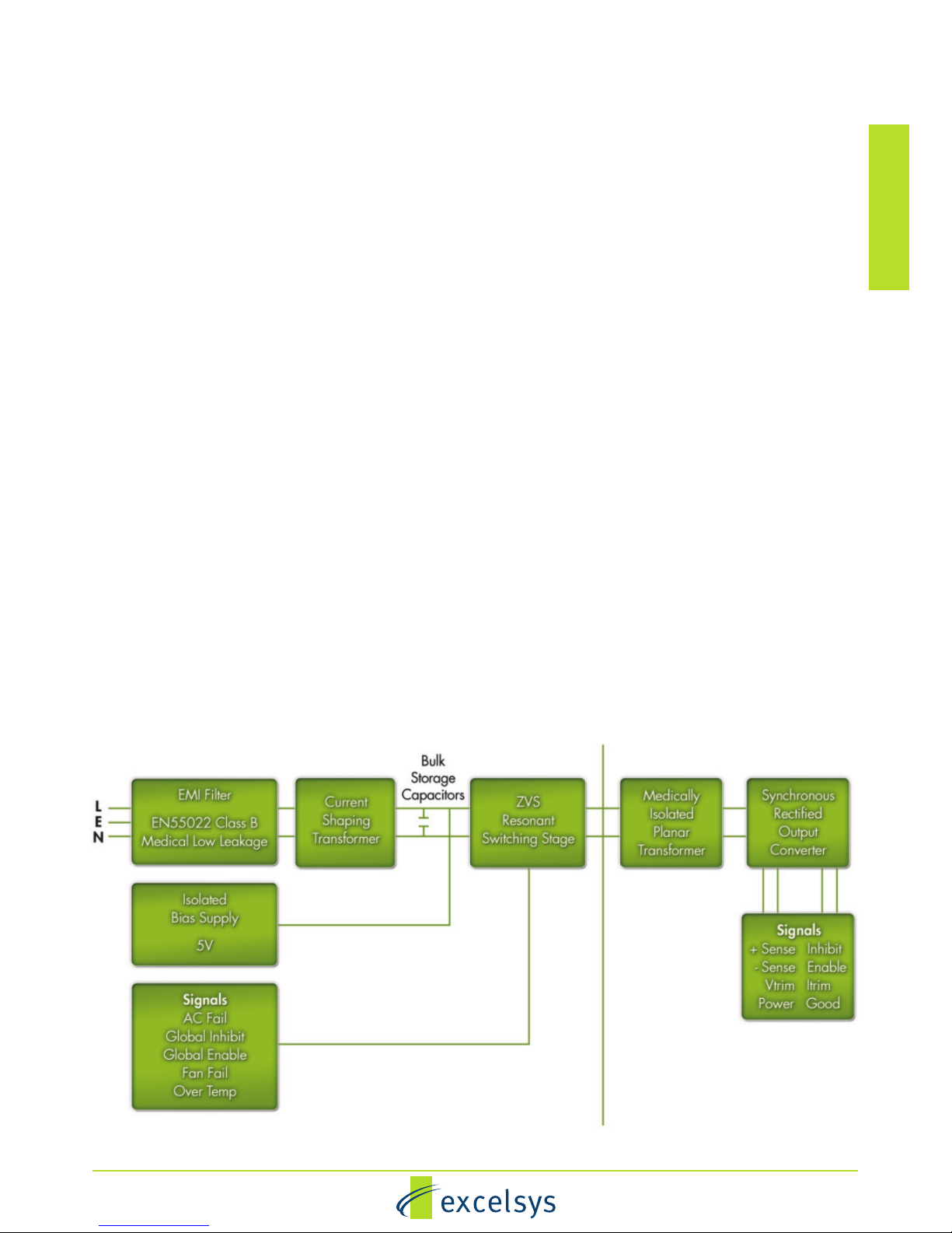
designer. See Operational Block Diagram.
The UltiMod powerPac modules consist of a fan-cooled semienclosed chassis containing circuitry for an off-line single phase
AC front end, EMI filter, cooling fan, customer interface and
associated housekeeping circuits. Input AC mains voltage
(L1/N, L2 and GND) is applied to an IEC320 type input
connector and then through an EMI filter designed to meet EN
55022 Level B. For medical applications, the EMI filter also
ensures the power supply meets the low earth leakage current
requirements of EN60601-1 3rd Edition.
Inrush current limited by an active soft start cct. Current is
limited by a combination of thermistors (UX4), and thermistors
and SCR's (UX6). This stage is then followed by a high
frequency switching input current shaping boost converter
feeding the ZVS (Zero Voltage Switching) resonant switching
stage. The ZVS stage supplies power to a variety of powerMod
assemblies that provide the desired low voltage, regulated
outputs. Conversion in the output assemblies is achieved by the
most advanced high efficiency converters resulting in reduced
UltiMod Designer Manual
Designer Manual
www.excelsys.com
3
size for magnetics and capacitors; excellent line and load
regulation; wide adjustment range for output and low EMI/RFI
emission.
At initial power-up, the UltiMod outputs are disabled to eliminate
inrush current and a low-power flyback converter operating with
PWM current mode control converts the high voltage DC bus
into regulated low voltage to power the internal housekeeping
circuits and cooling fans. Once the bus potential is within
operating parameters, the AC Fail signal is activated indicating
that the input power is ok, and allows the installed powerMod
outputs to come up. An auxiliary bias supply of 5 Vdc is provided
for peripheral use on interface connector J2. In the case of
medically approved supplies, this bias supply has medical
isolation (4000VAC).
Section 4.5
Configuration (and Reconfiguration)
powerMods may be easily added, replaced, or moved by sliding
the assemblies in or out of a powerPac chassis.
Prior to removing or installing a powerMod module, remove
power from the powerPac and wait 4 minutes. Failure to do so
can result in personal injury and/or damage to the supply. Take
standard ESD precautions when handling powerMods.
Configuring the UltiMod is as easy as 1,2,3!
1. Select the appropriate powerMods for your application.
2. Calculate your power requirements.
3. Select your appropriate powerPac for power and application
from the wide range of powerPacs.
Removing powerMods
powerMods may be removed by removing the screw on the top
surface. Once this screw has been removed the powerMod will
slide out of the chassis. Once a powerMod has been removed,
the empty slot MUST be filled with either another powerMod or
an empty slot cover. If the slot is left empty, it will provide an
airflow escape and may cause inadvertent shutdown of the unit
.
Operational Block Diagram
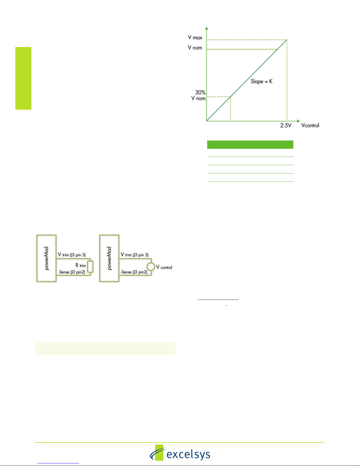
Remote Voltage Programming using a Resistor.
The powerMod output voltage can be adjusted downward using
a remote potentiometer or reduced, using an external
resistance.
Calculation of the the external resistance depends on the actual
initial voltage setting of the powerMod (via the onboard
potentiometer). The preferred method is to set the powerMod
voltage to its maximum rating. e.g. XgK set to 30V. This will
allow the widest possible adjustment range of the output
voltage.
powerMod set to Vmax
Rtrim= [3700V
out - 250K] (2)
[2.5K-Vout ]
Example.
Using a powerMod XgK, determine the resistance value to be
applied to Vtrim pin in order to set powerMod output voltage to
20V.
K for XgK = 12.5
Vout = 20V
Using equation (2)
Rtrim= 6300 ohm
Alternatively if the powerMod voltage is set to new level via the
on-board potentiometer to another level e.g. 21V then the
following formula must be used to calculate the value of Rtrim
www.excelsys.com
4
Installing powerMods
powerMods may be installed in empty slots by simply sliding in
the new powerMod, pushing the module ‘home’ until the
mounting bracket lines up with the hole in the Top Panel, then
securing the module with the M3 x 6 countersunk screw
provided. Power and interface connections can be made after
the powerMod has been installed.
powerMods may be paralleled for more power using bus bars
(Paralleling Links) across the positive and negative output
terminals. See Section 4.6 for details.
Section 4.6
powerMod Operation
The UltiMod has been designed to allow maximum flexibility in
meeting the unique requirements of individual users. The
inherent flexibility resulting from modularity concepts is further
enhanced by this flexibility. Although the products are very
versatile, care should always be taken to ensure that the proper
procedures are followed.
Voltage Adjustment
The UltiMod has been designed with maximum user flexibility as
a key objective. With regards to voltage adjustment this has been
achieved by the wide range of adjustment on each of the
powerMod models. Voltage adjustment may be achieved by:
1. Front-panel potentiometer adjustment (XgA - XgL)
2. Remote resistive programming (XgG - XgL)
3. Remote voltage programming (XgG - XgL)
See diagrams for details on external connections to the V trim
pin (J3 pin3) required for remote voltage programming(XgG XgL).
Remote Voltage Programming using a Voltage Source
Using an external Voltage source (V
control
), the powerMod
output voltage may be adjusted over a wide range. The
powerMod output voltage may be programmed by referring to
the Voltage Programming Graph and applying the formula
below to set the powerMod output voltage to the required level.
V
output
= K x V
control
(1)
The appropriate K factor for different powerMods are in the
‘Remote Output Voltage Adjustment’ table.
Important: V
control
must not exceed 2.5V.
Example.
Using a powerMod XgK, what external voltage must be applied
to Vtrim pin in order to set powerMod output voltage to 20V.
V
output
= 20V, K=12.5
Using equation (1); V
output
/K=V
control
20V/12.5 = 1.6V.
V
control
= 1.6V
Designer Manual
powerMod K
XgG 1.56
XgH 2.5
XgJ 6.23
XgK 12.5
XgL 24.2
Remote Output Voltage Adjustment of powerMods
Remote Output Voltage Adjustment of powerMods
Remote Output Voltage Adjustment Table
UltiMod Designer Manual
Rtrim = 1000Vout [(4.275 +Vp(1.96-4Vp)] -K(0.1Vp+0.051) (3)
K(Vp +0.51) -0.604Vout
where Vp is the powerMod setpoint voltage expressed as a
proportion of the total trim range and can be calculated using
formula (4).
Vp =(Vset-0.844K) (4)
1.656K
Example.
To set powerMod XgK to 15V when powerMod Vset is 12V.
K=12.5
Using equation (4) Vp = Vset-0.844K
1.656K
= 21-0.844(12.5)
1.656K(12.5)
Vp =0.51
Vout =15V
Using equation (3)
Rtrim = 1000Vout[(4.275+Vp(1.96-4Vp)] -K(0.1Vp+0.051)
[K(Vp +0.051) -604Vout]
Rtrim = 17,214 ohm
The power rating of the trim resistor can be as low as 100mW
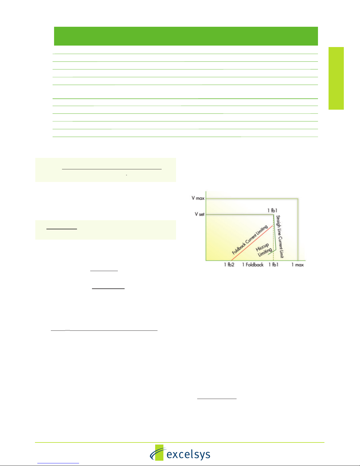
Over Current Protection (OCP)
A variety of over current protection methods are possible with the
Ultimod series. See the ‘Output powerMod Summary’ table
which indicates the available current limit modes on each
powerMod.
powerMods XgG to XgL can have Straight-line current limit or
Foldback current limit. See ‘Output powerMod Summary
Specifications’ table for nominal current limit values.
Simple external application circuits may be used to achieve
programmable foldback current and user programmable current
limit levels (reduced). See Current Limit Programming
www.excelsys.com
5
Designer Manual
UltiMod Designer Manual
diagrams and Foldback Programmable Current Limit diagram.
The default current limit characteristic is Straight Line Current
Limit.
Programming Current Limit
The current limit can be programmed to your requirements (in
both Straight line and Foldback modes).
Straight line Current Limit can be programmed using an external
voltage source or resistor/potentiometer. Connection between
the Itrim pin (J3 pin4 and the -Vout terminal) will set the current
limit to the desired level.
Straight Line Current Limit Using a Voltage Source
The formula below will calculate the required external control
voltage required to set the current limit of a powerMod:
If Current Limit is Less than 85% of Maximum Current
Itrim = FIlim + CF - 0.53 (5)
If Current Limit is Greater than 85% of Maximum Current:
Itrim = FIlim + CF - 1.325 (6)
0.558
Where F is a conversion factor for each powerMod and CF is a
correction factor.
Note that application of any voltage >2.5V to Itrim will not increase
Visit the UltiMod Online Configurator to get the best recommendation for your application at
www.excelsys.com/xgen_configurator/configure.html
Model Vnom Set Point Current Limit
Dynamic Vtrim Imax Power OVP 1 Remote Power
(V) Adjust Range (V)
Foldback Range (V) (A) (W) Tracking Sense Good
% of Vset (V)
XgA 12.0 10.8-15.6 - - 12.5 150 - - -
XgB 24.0 19.2-26.4 - - 8.3 200 - - -
XgC 36.0 28.8-39.6 - - 5.6 200 - - -
XgD 48.0 38.5-50.4 - - 4.2 200 - - -
XgE 24.0 5.0-28.0 - - 5.0 120 - - Yes
XgF 24.0 5.0-28.0 - - 3.0 72 - - Yes
24.0 5.0-28.0 - - 3.0 72 - - Yes
XgG 2.5 1.5-3.6 Yes 1.0-3.6 40.0 100 110-115% 0.5 Yes
XgH 5.0 3.2-6.0 Yes 1.5-6.0 36.0 180 110-115% 0.5 Yes
XgJ 12.0 6.0-15.0 Yes 4.0-15.0 18.3 220 110-115% 0.5 Yes
XgK 24.0 12.0-30.0 Yes 8.0-30.0 9.2 220 110-115% 0.5 Yes
XgL 48.0 24.0-58.0 Yes 8.0-58.0 5.0 240 110-115% 0.5 Yes
Current Limit Characteristics
Output powerMod Summary Specifications
 Loading...