

Page 1

RIDER'S HANDBOOK
Page 2
A
ll text, photographs, and illustrations in this handbook are based on the most
current product information available at the time of publication. Product
improvements or other changes may result in differences between this handbook
and the motorcycle. Excelsior-Henderson reserves the right to make production
changes at any time, without notice and without incurring any obligation to make
the same or similar changes to motorcycles previously built.
EXCELSIOR-HENDERSON MOTORCYCLE MANUFACTURING COMPANY
805 HANLON DRIVE • BELLE PLAINE, MINNESOTA 56011 • TELE: 952.873.7000/FAX: 612.656.4204
Copyright©2009 Excelsior-Henderson Motorcycle Manufacturing Company. All rights reserved. Excelsior-Henderson,
the X & Bar logo, Super X, the Super X Logo, Rider’s Handbook, X-Twin and Road Crew are trademarks of
Excelsior-Henderson Motorcycle Manufacturing Company. Dunlop is a registered trademark of Dunlop Tire Corporation.
Features of the Super X motorcycle are covered by U.S. Patent No. D.406,088 with additional patents pending.
Document part no. 6999-0001 Rev. D Printed in the United States of America
Page 3
10368
Page 4
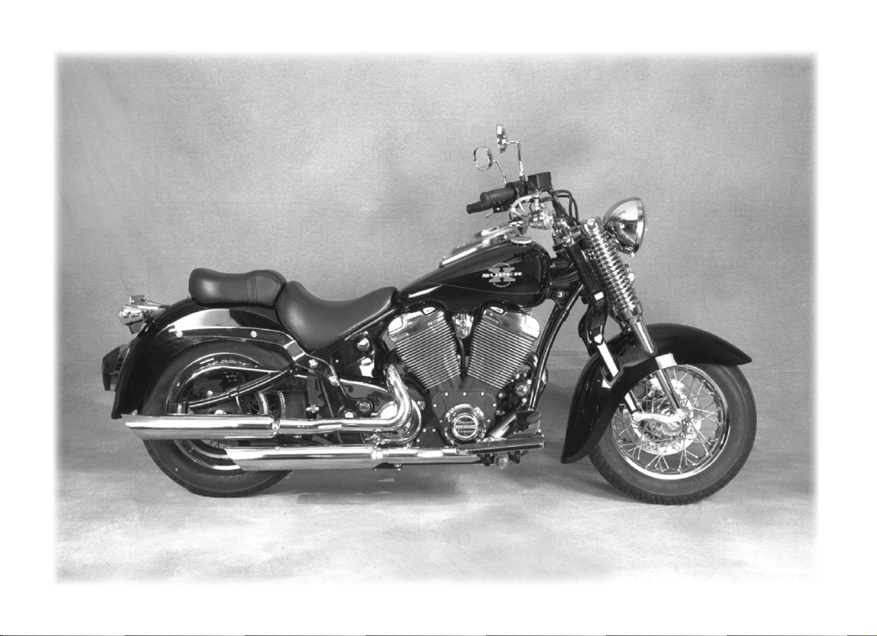
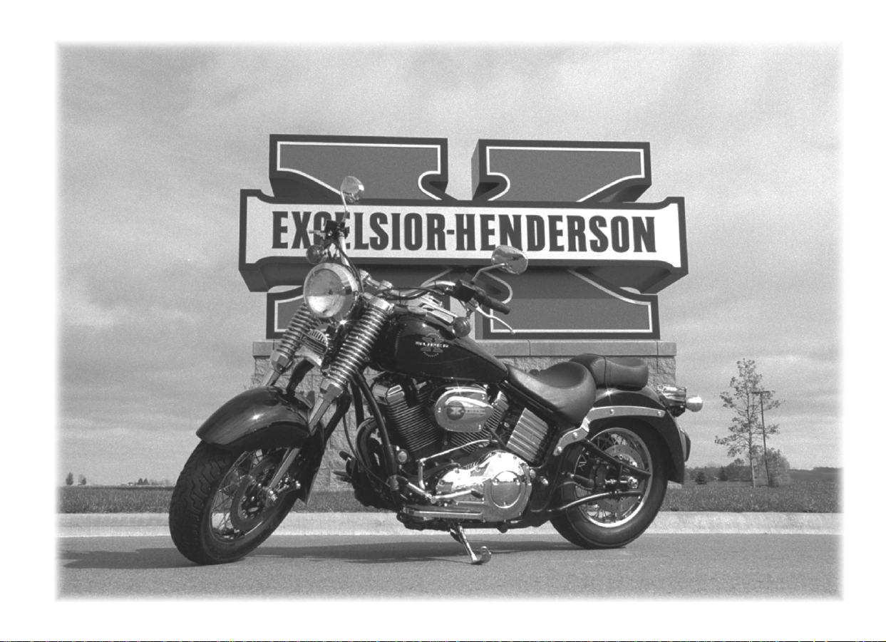
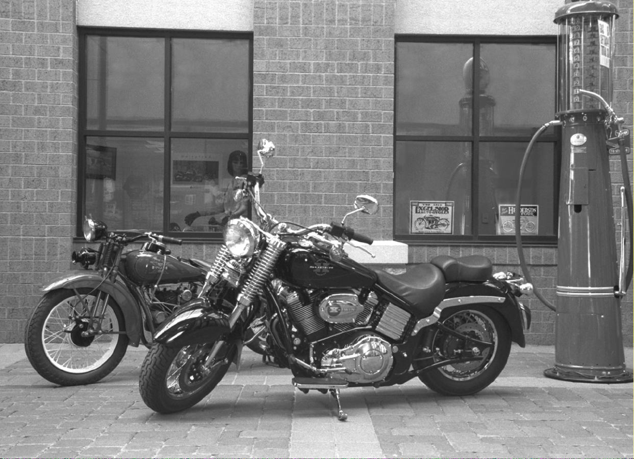
1999 Super X
10369
Page 5
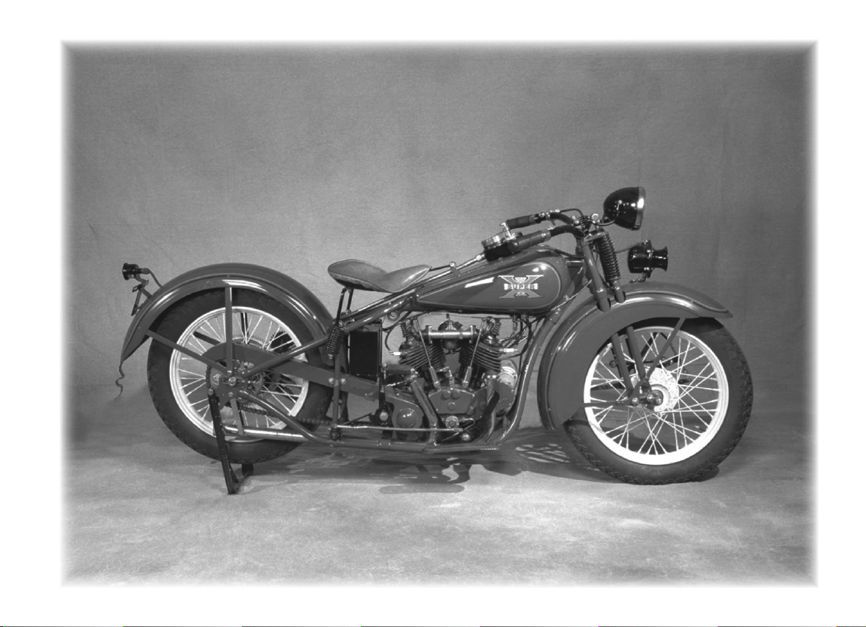
1931 Super X
10370
Page 6
10371
Page 7

Forward
Thank You!
The people of Excelsior-Henderson thank you for purchasing your new Super X
motorcycle. We appreciate your enthusiasm and faith in our products and in us.
Your new Super X is an American-made, premium-quality, heavyweight cruiser. It
combines advanced technologies with a style reminiscent of its ancestors. We have
designed, built, and will support your Super X in the tradition of The
Excelsior-Henderson Motorcycle Manufacturing Company.
i
Page 8

ii Forward
There’s More to The Rider’s Handbook
The Super X Rider’s Handbook contains information you need to operate
your Excelsior-Henderson Super X safely, responsibly, and with maximum
enjoyment. It also explains the routine maintenance, clea ning, and storage that
will help keep your Super X running and looking great for years to come.
To make the most of your Super X EXperience, this Handbook also includes
stories, photographs, and illustrations from throughout Excelsior-Henderson’s
history. In the section “The Tradition of the State of the Art” the Rider’s
Handbook introduces you to the heritage that is an essential part of the ExcelsiorHenderson EXperience and reestablishes our place in the history of American
motorcycling.
You, the Super X, and the Excelsior-Henderson Motorcycle Manufacturing
Company each have a place in the continuing history of American motorcycling.
• As a Super X owner, you make your own contribution to the
Excelsior-Henderson heritage that began over a century ago and continues with
today’s Excelsior-Henderson Motorcycle Manufacturing Company.
• The 1999 Super X bears the rich heritage of the original Super X and its
manufacturer’s history and tradition.
• The Excelsior-Henderson Motorcycle Manufacturing Company is the first
American manufacturer to successfully revive an original American motorcycle
brand.
Page 9

F
orward
y
J
“It’s not so much the destination that matters, but the journey” —motorcyclists
may understand this better than anyone. When you twist the throttle of your
Super X along an open stretch of highway or through a deep curve, you will
discover the roar of the X-twin™ engine as the road disappears behind you. With
the images and stories of Excelsior-Henderson’s present and past in mind, you will
EXperience the spectacular vision of the journey before you. Enjoy the ride!
From the Hanlon Famil
On behalf of the entire Excelsior-Henderson Road CrewTM, we welcome you to
our family. When you own an Excelsior-Henderson Super X, you own much more
than just a motorcycle, you own an enduring legacy of quality and
performance. You are part of the American dream…and you are part of
our dream. Together we will make motorcycling history as we bring back
the most legendary brand of the past —Excelsior-Henderson.
The Excelsior-Henderson team members are proud you selected the Super
X, as we have designed and manufactured the Super X to the highest
standards. This Rider’s Handbook has been specially prepared and
detailed to show you our commitment to ensure motorcycling fun.
We wish you a safe and pleasurable ride as together we carry forward a
proud tradition that dates back to 1876. So, get ready to throw a leg over
your Super X and join us on the highways of this great country, the United
States of America.
iii
10372
Dan Hanlon
ennie Hanlon Dave Hanlon
Page 10
10374
Page 11

Contents
Introduction....................................................................1
Read the Rider’s Handbook................................................1
Hazard Symbol and Terms in the Rider’s Handbook.............2
Safety Information ..........................................................5
Safe Riding.......................................................................6
Super X Design Characteristics......................................6
Safe Riding Practices....................................................7
Carrying a Passenger..................................................11
Transporting the Super X ...........................................12
Protective Apparel...........................................................12
Product Modifications ......................................................13
Gross Vehicle Weight Rating............................................14
Loading..........................................................................15
Selecting and Installing Accessories...................................17
Gasoline and Exhaust Gases.............................................18
v
Parking ..........................................................................19
Maintenance...................................................................20
Safety and Vehicle Information Labels...............................22
Page 12

vi Contents
Product Description ...................................................... 27
Instruments and Controls ..............................................35
Reporting Safety Defects.................................................25
Vehicle Components.......................................................28
Vehicle Identification Number (VIN)..................................30
Engine Identification Number...........................................31
Key Identification Number ...............................................32
Location ........................................................................35
Key ............................................................................... 37
Fork Lock ......................................................................37
Main Switch...................................................................38
Instrument Pod...............................................................40
Indicator Lights..........................................................40
Headlamp High Beam Indicator.............................41
Check Engine Indicator .........................................41
Turn Signal Indicator.............................................41
Neutral Indicator...................................................42
Low Oil Pressure Indicator.....................................42
Low Battery Voltage Indicator................................42
Low Fuel Indicator................................................43
Page 13

Speedometer .............................................................43
Odometer/Trip Meter............................................43
Odometer/Trip Meter Function Button ...................44
Tachometer...............................................................44
Fuel Gauge................................................................44
Handlebar Controls .........................................................45
Left Side Handlebar Controls ......................................45
Clutch Lever.........................................................45
Left Mirror............................................................45
Headlamp Dimmer Switch .....................................46
Turn Signal Switch................................................46
Horn Button.........................................................46
Right Side Handlebar Controls ....................................47
Front Brake Lever.................................................47
Throttle Control Grip.............................................47
Right Mirror..........................................................47
Engine Stop/Run Switch........................................48
Emergency Flasher Switch .....................................48
Electric Starter Button............................................49
viiContents
Foot Controls..................................................................49
Page 14

viii Contents
Pre-Operation Check.....................................................63
Gear Shift Pedal ........................................................49
Rear Brake Pedal.......................................................50
Fuel Cap........................................................................50
Rear Suspension Adjustment............................................51
Location of Adjusters .................................................52
Factory Adjustment Settings........................................52
Adjusters and Their Setting Ranges .............................52
Changing Adjustment Settings .................................... 53
Changing Preload Adjustment................................54
Changing Damping Rate Adjustment......................57
Effects of Rear Suspension Adjustments.......................58
Sidestand.......................................................................61
Saddles..........................................................................61
Fuel...............................................................................64
Fuel Level .................................................................64
Fuel Hose, Rail, and Connections................................64
Evaporative Emission Control System
(California model only)................................................64
Engine Oil Level .............................................................65
Page 15

Tires ..............................................................................66
Tire Pressure .............................................................66
Tire Condition ...........................................................67
Tread Depth..............................................................67
Drive Belt.......................................................................68
Steering..........................................................................68
Hydraulic Controls — Clutch and Brakes...........................68
Check Hoses and Connections....................................68
Check Front Brake & Clutch Fluid Level.......................69
Check Rear Brake Fluid Level......................................69
Check Clutch Lever Movement....................................69
Check Front Brake Lever Movement............................70
Check Rear Brake Pedal Movement.............................70
Check Brake Pads...........................................................71
Throttle Control Grip and Cables......................................71
Electrical Equipment........................................................72
Engine Stop/Run Switch.............................................72
Instrument Pod ..........................................................72
Headlamp..................................................................73
ixContents
Brake Light................................................................73
Page 16

x Contents
Operation and Riding....................................................77
Maintenance .................................................................95
Running Lights.......................................................... 73
Turn Signals..............................................................73
Sidestand.......................................................................74
Fasteners .......................................................................74
Operating During Break-In Period (First 500 Miles)............78
Fueling and Fuel Fill Height .............................................79
Starting the Engine .........................................................80
Jump-Starting............................................................82
Shifting Gears.................................................................84
Recommended Shift Points..............................................87
Accelerating...................................................................88
Braking..........................................................................89
Stopping the Engine .......................................................90
Parking..........................................................................91
New Motorcycle Break-In Maintenance.............................96
Periodic Maintenance Intervals.........................................96
Engine Oil......................................................................99
Change Oil and Oil Filter............................................99
Page 17

Check Oil Level........................................................101
Air Filter Element..........................................................103
Drive Belt.....................................................................104
Check Drive Belt Tension .........................................104
Adjust Drive Belt Tension..........................................105
Check Drive Belt Condition.......................................106
Throttle........................................................................107
Check Throttle Control Grip and Cables.....................107
Adjust Throttle Freeplay............................................107
Fuel Hose, Rail, and Connections...................................108
Evaporative Emission Control System
(California model only)..............................................108
Oxygen Sensor .............................................................109
Hydraulic Controls — Clutch and Brakes.........................110
Check Hoses and Connections..................................110
Check Front Brake & Clutch Fluid Level.....................110
Check Rear Brake Fluid Level....................................111
xiContents
Add Hydraulic Fluid..................................................111
Check Clutch Lever Movement..................................112
Check Front Brake Lever Movement..........................113
Page 18

xii Contents
Check Rear Brake Pedal Movement ..........................113
Check Brake Pads.........................................................114
Spark Plugs..................................................................114
Inspect Spark Plugs..................................................114
Remove Spark Plugs................................................ 115
Replace Spark Plugs ................................................116
Saddles........................................................................117
Tandem Saddle........................................................117
Rider’s Saddle..........................................................118
Battery.........................................................................119
Remove Battery.......................................................120
Charge Battery........................................................121
Install Battery ..........................................................122
Electrical Equipment......................................................123
Replace Fuse...........................................................123
Check Engine Stop/Run Switch................................124
Check Instrument Pod Lights.................................... 124
Replace Instrument Pod Light Bulb............................125
Check Headlamp.....................................................125
Replace Headlamp Sealed Beam Lamp .....................126
Page 19

Check Brake Light ...................................................126
Replace Brake/Tail or License Plate Light Bulb...........127
Check Running Lights ..............................................127
Check Turn Signals ..................................................128
Replace Turn Signal/Running Light Bulb....................128
Steering........................................................................129
Inspect Steering Movement.......................................129
Inspect Steering Head Bearings.................................129
Tires ............................................................................130
Check Tire Pressure .................................................130
Check Tire Surface Condition....................................130
Check Tread Depth..................................................130
Wheels.........................................................................131
Check Spokes..........................................................131
Remove Front Wheel................................................132
Inspect Front Wheel Bearings....................................133
Install Front Wheel ...................................................134
Remove Rear Wheel.................................................135
Inspect Rear Wheel Bearings.....................................137
xiiiContents
Install Rear Wheel ....................................................138
Page 20

xiv Contents
Cleaning and Storage..................................................145
Align Rear Wheel.....................................................139
Sidestand.....................................................................141
Fasteners .....................................................................141
Road Test ....................................................................142
Cleaning ......................................................................145
Washing and Drying.................................................146
Waxing, Polishing, and Applying Protectants..............148
Repairing Painted Surface Damage ...........................149
Storage........................................................................149
Preparing for Storage...............................................150
Choose an Adequate Storage Location................. 150
Clean and Protect the Motorcycle.........................150
Stabilize Fuel......................................................151
Protect Engine Components................................ 151
Inflate Tires........................................................152
Remove, Clean, and Store Battery .......................152
Park and Cover the Motorcycle............................153
Maintaining During Storage...................................... 153
Removing from Storage ...........................................153
Page 21

Our Tradition of State of the Art.................................. 157
Traditions Alive Today ..................................................160
The 1999 Super X ..................................................160
The Company.........................................................166
The Road from 1993 through 1998...............................172
The Trail from 1876 through 1931................................185
1876-1910: The Beginnings of Excelsior...................186
1911-1917: The Joining of Forces ...........................190
1918-1925: Excelsior-Henderson and The Super X....210
1926-1931: The Birth of the “Cruiser” .....................224
Specifications............................................................. 235
Fuel Specifications........................................................238
Engine Oil Specifications...............................................239
Torque Specifications....................................................240
Identification Numbers for Your Super X.........................242
Index ......................................................................... 245
xvContents
Page 22
10375
Page 23

Introduction
Read the Rider’s Handbook
The Rider’s Handbook contains information that is essential to safe riding and
proper maintenance of your Super X motorcycle. Read it thoroughly before you
ride. Understand and follow the procedures in the Rider’s Handbook to keep
your Super X in top condition on the road or in storage. Failure to follow
operation and maintenance procedures may result in injury to you, your
passenger, or damage to your Super X. We want you to enjoy motorcycling.
Following the safety and maintenance procedures will add to your enjoyment, and
keep you riding.
1
Page 24
2 Introduction
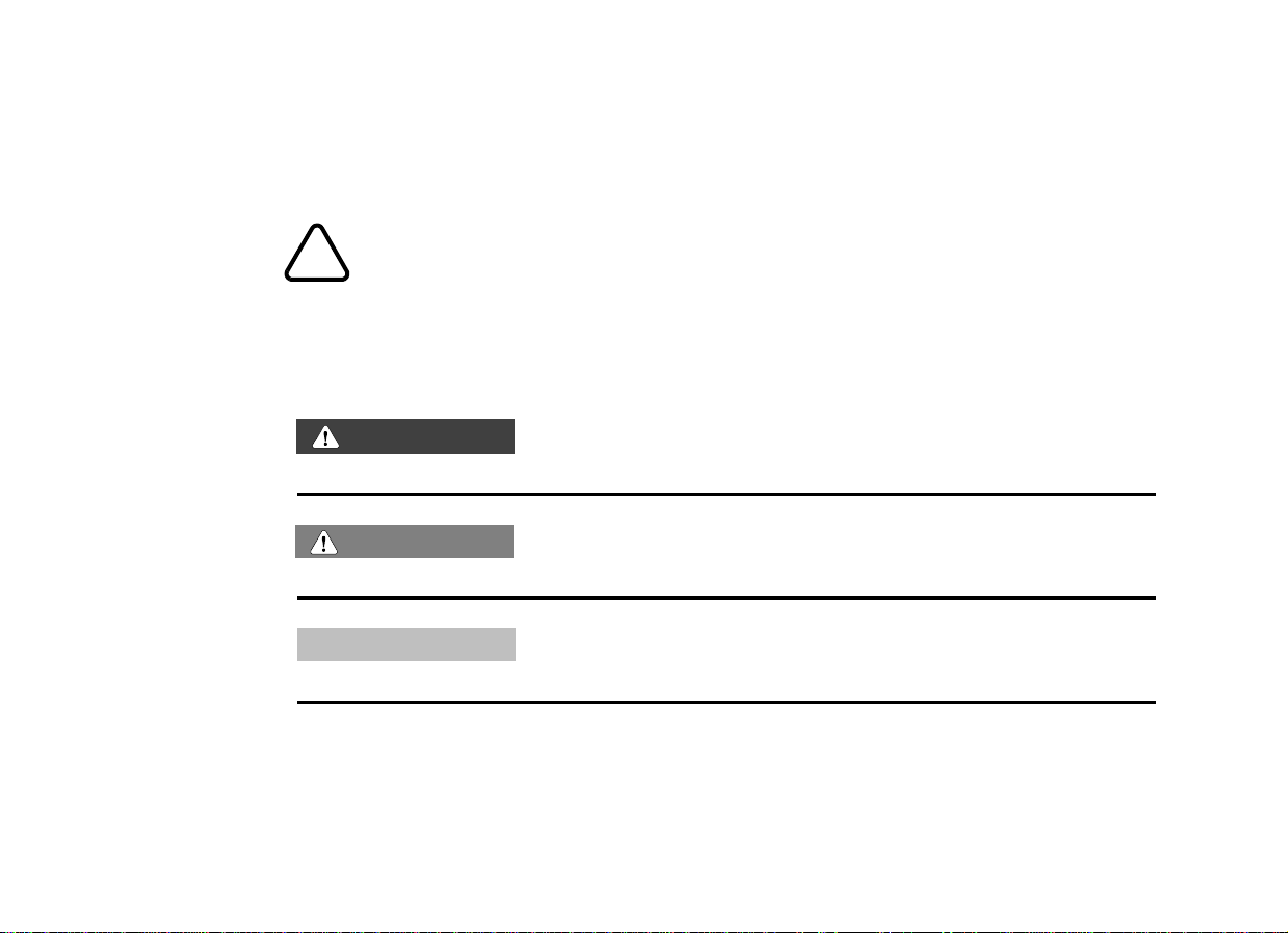
Hazard Symbol and Terms in the Rider’s Handbook
The hazard symbol indicates a potential hazard to you, others, or your
motorcycle. Pay special attention to information in the
!
Rider’s Handbook that begins with this symbol.
The following terms have special meaning in the Rider’s Handbook. Be certain
you understand the meaning of each term, as the terms communicate important
information about the Super X and its operation and maintenance.
WARNING
Indicates a potential hazard that could injure you or others.
Caution
Indicates a potential hazard that could damage the motorcycle.
Notice
Emphasizes important information that might otherwise be overlooked.
Page 25

Notes:
3Introduction
Page 26
10376
Page 27

Safety Information
This section contains information to help you operate your Super X motorcycle
safely and enjoyably while minimizing risk to you, your passenger, and others.
Your ability to safely operate the Super X depends on your judgment and use of
safe riding techniques. Motorcycling has inherent risks. You can minimize those
risks, but you can’t eliminate them completely.
We want to keep you riding. Take the time to read and understand the following
information to help minimize risk and maximize pleasure when operating the
Super X. Even if you are an experienced rider , read this section and the rest of the
Rider’s Handbook before riding the Super X.
• Read, understand, and use the information contained in this section. This
section contains safety information specific to the Super X, as well as
information about general motorcycle safety.
• Read and understand the entire Rider’s Handbook before operating the
Super X; the Handbook contains safety information throughout. Also pay
attention to the maintenance requirements in this Handbook. For professional
technical service specified in the Rider’s Handbook or required by mechanical
circumstances, see the Super X Service Handbook or your authorized
Excelsior-Henderson Dealer.
5
• Read, understand, and use the information in the booklet you received with
your Super X, You and Your Motorcycle — Riding Tips (Excelsior-Henderson
Page 28

6 Safety Information
document part no. 6999-0008). The booklet contains general information
about safe motorcycle operation and tips for developing safe riding habits.
• Take a rider education course from the Motorcycle Safety Foundation (MSF) or
another qualified instructor. The course will help you develop or refresh your
expertise in safe riding habits through instruction and riding. For information on
MSF rider education courses, see the pamphlet you received with your Super X,
Rider Course (Excelsior-Henderson document part no. 6999-0066).
• Until you are thoroughly familiar with the Super X and all of its controls,
practice riding where there is little or no traffic. Practice riding at moderate
speed on varying road surfaces and under varying weather conditions.
Safe Riding
Super X Design Characteristics
The following Super X design characteristics affect how you should ride the
motorcycle:
• The Super X is designed for on-road use with one rider and one passenger. Do
not exceed the gross vehicle weight rating (see Specifications or the
certification label on the steering head). Riding off-road, riding with more than
one passenger, or carrying weight exceeding the maximum weight rating can
make handling difficult, which could cause you to lose control of the motorcycle.
Page 29

• In the first 500 miles, operate the Super X according to the break-in procedures
described in “Operating During Break-In Period (First 500 Miles)‚” page 78.
Operating the Super X without following break-in procedures can result in
serious engine damage.
• The Super X is designed not to “dive” when the front brake is applied. “Diving”
is the tendency for the front suspension to compress rapidly when the front
brake is applied. The anti-dive design of the Super X makes braking more
positive and stable than on motorcycles without an anti-dive design. If you have
ridden motorcycles without an anti-dive design, the Super X may initially feel
different when you apply the front brake.
Safe Riding Practices
Follow these general safe riding practices:
• Before you ride, make sure you can operate the Super X safely and properly by
following the recommendations given at the beginning of the Safety
Information section.
7Safety Information
• Before you ride each time, make the checks described in the Pre-Operation
Check section. Operating the Super X without making the pre-operation
checks can cause damage to the motorcycle or result in an accident.
• Know your skills and limits, and ride within them.
• Allow only licensed, experienced operators to ride your Super X, and then only
after they have become familiar with its controls and operation.
Page 30

8 Safety Information
• Do not ride when you are fatigued or under the influence of alcohol,
prescription drugs, over-the-c ounter drugs, or any other drugs. Fatigue, alcohol,
and drugs can cause drowsiness, loss of coordination, loss of balance, and can
affect your awareness and judgment.
• If your Super X operates abnormally, correct the problem immediately (see the
Super X Service Handbook or contact your authorized Excelsior-Henderson
Dealer). If you continue to operate the Super X in this condition, you are likely
to aggravate the initial problem, increase the cost of repairs, and threaten your
safety.
• The most common cause of accidents involving a motorcycle and an automobile
is the automobile driver’s failure to see the motorcycle. Ride defensively, as if
you are invisible to other motorists, even in broad daylight. Ride where you are
visible to other motorists and observe their behavior carefully, as they may not
see or be aware of you.
• Be especially cautious at an intersection, as this is the most likely place for an
accident. Remember that you are more vulnerable to injury on a motorcycle
than in an enclosed vehicle.
• To prevent loss of control while operating the motorcycle, keep your hands on
the handlebars and your feet on the footrests.
• Obey the speed limit and adjust your speed and riding technique based on road,
weather, and traffic conditions. As you travel faster, the influence of all other
Page 31

conditions increases, which can lessen the motorcycle’s stability and increase
the possibility of your losing control of the motorcycle.
• Do not move or operate the motorcycle with the forks locked, as steering is
severely restricted and you could drop or lose control of the motorcycle.
• If in doubt, reduce your speed when:
- The road has potholes or is otherwise rough or uneven.
- The road has sand, dirt, gravel or other loose substances on it.
- The road is wet, icy, or oily.
- The road contains painted surfaces, manhole covers, metal grating, railway
crossings, or other slippery surfaces.
- The weather is windy, raining, or otherwise causing slippery or rapidly
changing conditions.
- The traffic is heavy, congested, not allowing sufficient space between
vehicles, or otherwise not flowing smoothly.
9Safety Information
- You are being passed in either direction by a large vehicle that produces a
wind blast in its wake.
• To maximize braking effectiveness, use the front a nd rear brakes together. Be
aware of the following braking facts and practices:
- The rear brake provides 40% of the motorcycle’s stopping power, at most.
Page 32

10 Safety Information
- Consider road conditions before applying the brakes; when the road is wet,
rough, or contains loose or other slippery substances, apply the brakes
gradually.
- Bring the motorcycle to upright position before applying the brakes, and
avoid applying the brakes in a corner if at all possible. When the motorcycle
is leaned, the amount of tire surface contacting the road is reduced,
decreasing tire traction and increasing the possibility of the tires skidding
when you apply the brakes.
- Improper braking may cause you to lose control of the motorcycle or may not
slow you in time to avoid a collision.
• As you approach a curve, choose a speed and a lean angle that allow you to
pass through the curve in your own lane without applying the brakes. Excessive
speed, improper lean angle, or braking in a curve can cause you to lose control
of the motorcycle.
• Ground clearance is reduced when you lean the motorcycle. Do not allow
components to contact the road surface when leaning the motorcycle in a
curve, as this could cause you to lose control of the motorcycle.
• Retract the sidestand fully before riding. If the stand is not fully retracted while
you are riding, it could contact the road surface and cause you to lose control of
the motorcycle.
• Do not tow a trailer. Towing a trailer can make the motorcycle hard to handle
and cause you to lose control of the motorcycle.
Page 33

Carrying a Passenger
To carry a passenger safely, do the following:
• Direct the passenger to hold onto you, or the saddle strap, with both hands and
to keep both feet on the passenger footrests. Do not carry a passenger who
cannot place both feet firmly on the passenge r footrests. A passenger who is
not holding on properly or who cannot reach the passenger footrests can shift
erratically, which can make the motorcycle hard to handle and cause you to lose
control of the motorcycle.
• If necessary, adjust the rear shock absorber preload and damping rate according
to the instructions in “Changing Preload Adjustment‚” page 54, and “Changing
Damping Rate Adjustment‚” page 57. Improper preload or damping rate
adjustment can make your motorcycle hard to handle and cause you to lose
control of the motorcycle.
• Before you ride, be sure your passenger knows safe riding procedures. Discuss
any safety information unfamiliar to your passenger. A passenger who is
unaware of safe riding procedures may distract you or make movements that
make the motorcycle hard to handle and cause you to lose control of the
motorcycle.
11Safety Information
• Adjust your riding style to compensate for the differences in handling,
acceleration, and braking caused by the additional weight of the passenger.
Failure to do so can cause you to lose control of the motorcycle.
Page 34

12 Safety Information
Transporting the Super X
If you must transport the Super X, do the following:
• Use a truck or trailer. Do not tow the Super X with another vehicle, as the
motorcycle’s steering and handling will be impaired by towing, which can cause
you to lose control of the motorcycle.
• Position and restrain the Super X so it is kept upright on the truck or trailer, as
gasoline may leak out of the fuel tank if the motorcycle leans over. Leaked
gasoline is a fire hazard and can also damage the finish and components of the
Super X.
Protective Apparel
We respect your right to make your own choices. However, we recommend that
you wear an approved helmet and eye protection. Some state laws require that
you wear an approved helmet, eye protection, or both. In accidents involving
motorcycles, head injuries are the leading cause of motorcyclist fatalities, and
statistics prove that an approved helmet is the most effective protection in
preventing or reducing head injuries. Eye protection reduces the chance that your
vision could be impaired by wind or by airborne particles and objects.
You and your passenger should wear bright or light colored and/or reflective
clothing to improve your visibility to other motorists. A motorist’s failure to see or
recognize a motorcycle is the leading cause of automobile/motorcycle accidents.
Page 35

Wear gloves, heavy boots and pants, and a jacket to prevent or reduce abrasions,
lacerations, or burns that you can suffer if you fall. Wear boots with low heels
because boots with high heels can catch on pedals or footrests. The combination
of your boots and pants should completely cover your legs, ankles, and feet,
protecting you from engine and exhaust system heat. The engine and exhaust
system get hot soon after the engine is started, and stay hot for about half an hour
after the engine is turned off.
Do not wear loose, flowing clothing or long boot laces, as they can catch on
components like handlebars, levers, or footrests, or get caught in the wheels,
causing you to lose control of the motorcycle.
Product Modifications
Modifying the Super X by removing any equipment or adding equipment not
approved by Excelsior-Henderson may void your warranty. Such modifications
may also make the motorcycle unsafe to ride and could severely injure you or
others or damage the motorcycle. Some modifications may be illegal in some
states. If in doubt, contact your authorized Excelsior-Henderson Dealer.
13Safety Information
Page 36

14 Safety Information
Gross Vehicle Weight Rating
Gross vehicle weight is the total weight of the motorcycle, the rider, and the
passenger.
• The weight of the motorcycle includes: the motorcycle and all its fluids; any
accessories and their contents; and any additional cargo on the motorcycle.
• The weight of the rider or passenger includes: body weight, all apparel, and
objects in or on apparel.
WARNING
Do not exceed the motorcycle’s gross vehicle weight rating. Exceeding the
weight rating can lessen stability and handling and could cause you to lose
control of the motorcycle.
The gross vehicle weight rating of the Super X is 1140 lb. The total weight of the
Super X is approximately 700 lb with a full capacity of all fluids, and without any
accessories or cargo. The combined weight of the rider, passenger, accessories,
and cargo cannot exceed 440 lb. The following two examples show how to stay
within the gross vehicle weight rating.
Page 37

Example 1: Super X with no accessories or cargo
Item Weight
Super X with full capacity of all fluids 700 lb
Rider - dressed and ready to ride 260 lb
Passenger - dressed and ready to ride 180 lb
Total gross vehicle weight 1140 lb
Example 2: Super X with all accessories and cargo
Item Weight
Super X with full capacity of all fluids 700 lb
Excelsior-Henderson accessories 80 lb
Attached cargo 35 lb
Rider - dressed and ready to ride 205 lb
Passenger - dressed and ready to ride 120 lb
Total gross vehicle weight 1140 lb
15Safety Information
Loading
WARNING
Adding additional weight to the Super X can affect its stability, handling
characteristics, and safe operating speed.
Page 38

16 Safety Information
Use the following guidelines when attaching cargo or accessories to the Super X.
Where applicable, these guidelines refer to accessories and their contents.
• Keep cargo and accessory weight to a minimum, and keep it as close to the
motorcycle as possible, to minimize a change in the motorcycle’s center of
gravity. Changing the center of gravity can lessen stability and handling and
could cause you to lose control of the motorcycle.
• Distribute weight evenly on both sides of the motorcycle. Maintain even weight
distribution by checking accessories and cargo to make sure they are securely
attached to the Super X before riding and whenever you take a break while
riding. Uneven weight distribution, or accessories or cargo that shift suddenly
while you are riding, can make the motorcycle hard to handle and cause you to
lose control of the motorcycle.
• Do not attach large or heavy cargo such as sleeping bags, duffle bags, or tents
to the handlebars, front fork area, or front fender. If you add accessories to the
handlebars or the front fork area, they must be as small and as lightweight as
possible. Cargo or accessories placed in any of these areas can cause instability
due to improper weight distribution or aerodynamic changes, and can cause
you to lose control of the motorcycle. Such items can also block air flow to the
engine and could cause overheating that can damage the engine.
• Do not exceed the maximum cargo weight limit of any accessory (see accessory
instructions and labels), and do not attach cargo to an accessory not designed
Page 39

for that purpose, as either of these could result in an accessory failure that could
cause you to lose control of the motorcycle.
Selecting and Installing Accessories
WARNING
Adding accessories to the Super X can affect its stability, handling
characteristics, and safe operating speed.
Because Excelsior-Henderson cannot test and make specific recommendations
concerning every accessory or combination of a ccessories sold, you are
responsible for determining that your Super X can be safely operated with
accessories you install or additional weight you carry. Use the following guidelines
when choosing and mounting accessories:
• Do not install accessories that impair the stability, handling, or operability of the
Super X. Before installing an accessory, be sure that it does not:
17Safety Information
- Reduce ground clearance when the motorcycle is either leaned or in a vertical
position.
- Limit suspension or steering travel or your ability to operate controls.
- Displace you from your normal riding position.
- Obscure lights or reflectors.
Page 40

18 Safety Information
Bulky or large accessories can make the Super X unstable due to the lifting or
buffeting effects of wind and can cause you to lose control of the motorcycle.
• Do not install electrical accessories that exceed the capacity of the Super X’s
electrical system. An electrical failure could result and cause hazardous loss of
engine power or lights, or damage to the electrical system.
• If you want to add a windshield, backrest, or luggage rack, choose one designed
and approved by Excelsior-Henderson specifically for the Super X, and follow
the instructions for proper installation and use. An improperly designed or
installed windshield, backrest, or luggage rack can reduce stability, causing you
to lose control of the motorcycle.
Gasoline and Exhaust Gases
For fueling procedures, see “Fueling and Fuel Fill Height‚” page 79.
Gasoline is highly flammable and can be explosive in certain conditions. Observe
the following precautions when you refuel or service the fuel system:
• Turn off the engine.
• Use a well-ventilated area.
• Remove the fuel cap slowly.
Page 41

• Do not spill gasoline on the engine or the exhaust system. Immediately wipe, or
rinse with water, gasoline spilled on any part of the Super X or the surrounding
area.
• Do not smoke while fueling.
• Do not fuel in an area where there are sparks or open flame.
Gasoline and gasoline vapors are poisonous and can cause severe injury. Do not
swallow gasoline, inhale gasoline vapors, or spill gasoline on yourself or your
clothes. If you swallow gasoline, inhale more than a few breaths of gasoline vapor,
or get gasoline in your eyes, see a physician immediately. If you spill gasoline on
your skin, wash it off immediately with soap and water. If you spill gasoline on
your clothes, change your clothes immediately.
Exhaust gases contain carbon monoxide, a colorless, odorless gas that can cause
unconsciousness or severe injury. Observe the following precautions to avoid the
effects of exhaust gases:
• Do not breathe exhaust gases.
19Safety Information
• Do not start or run the engine in a closed area.
Parking
For complete parking procedures, see “Parking‚” page 91.
Page 42

20 Safety Information
When leaving the Super X unattended, turn the engine off, lock the main switch
and the fork lock, and take the main switch key with you.
The engine and exhaust system are very hot after the engine has been running.
Therefore, park the Super X where people are not likely to touch the engine or
exhaust system or place combustible materials in close proximity to these hot
areas.
Do not park near a flammable source such as a kerosene heater or an open flame,
as the Super X could catch fire.
Park on a level, firm surface if possible. Sloped or soft surfaces may not support
the Super X adequately when it is parked, and it may fall over . If you must park on
a sloped or soft surface, reduce the likelihood of the Super X falling over by
following the procedures described in “Parking‚” page 91.
Maintenance
Maintain the Super X according to the following requirements:
• Before you ride each time, make the checks described in the Pre-Operation
Check section. Operating the Super X without making the pre-operation
checks can cause damage to the motorcycle or result in an accident.
• Perform periodic maintenance according to the intervals specified in “Periodic
Maintenance Intervals‚” beginning on page 96. Operating the Super X without
performing periodic maintenance can damage the motorcycle or injure you.
Page 43

• Maintain proper tire inflation pressure and tread condition, and proper wheel
and tire balance. Inspect tires regularly and replace them if they are worn or
damaged. Use only an approved replacement tire and see the Super X Service
Handbook or your authorized Excelsior-Henderson Dealer for tire replacement.
Operating the Super X with improper tire pressure or tread condition, or
improper wheel or tire balance, can make the motorcycle hard to handle and
cause you to lose control of the motorcycle.
• Check proper steering head bearing adjustment. Regularly inspect the rear
shock absorber and the front forks. Check for leaks. Operating the Super X
with a loose, worn, or damaged steering system or front or rear suspension
system can make the motorcycle hard to handle and cause you to lose control
of the motorcycle. T o repair steering or suspension system wear or damage, see
the Super X Service Handbook or contact your authorized
Excelsior-Henderson Dealer.
• Keep equipment required by federal, state, and local laws in place and in good
working condition. Your license plate must be clean, clearly visible in all
conditions, and installed in a position specified by law.
21Safety Information
• Each fastener used in the Super X meets our quality specifications for strength,
finish, and type. If you need a replacement fastener, use only a genuine
Excelsior-Henderson fastener, tightened to the proper torque. A fastener that
does not meet original specifications could fail and damage the motorcycle or
injure you.
Page 44

22 Safety Information
Safety and Vehicle Information Labels
10378
Super X — left side view (all models)
VEHICLE EMISSION CONTROL INFORMA TION
1
Engine Displacement: 1386CC
Engine Family: XEMCC01.4001
Engine Exhaust Emission Control: SMFI
Engine Tune Up Specifications
Idle Speed: 900 - 950 RPM
Ignition Timing: Fixed
Fuel: Unleaded Gasoline only, 92 pump octane or higher.
Oil: See Rider’s Handbook
This vehicle conforms to USEPA Regulations applicable
to 1999 Model Year new motorcycles.
EXCELSIOR-HENDERSON MOTORCYCLE
MANUFACTURING COMPANY
4
2
!
WARNING: The rear shock
absorber contains nitrogen gas under
high pressure. To prevent injury, do not
disassemble, rebuild, puncture, or
apply heat to the shock absorber.
See Rider’s Handbook.
(Under seat)
3
WARNING
USE ONLY DOT5 BRAKE FLUID
FROM A SEALED CONTAINER.
CLEAN FILLER CAP BEFORE
REMOVING.
Also on rear
brake and clutch
reservoirs.
(Not shown.)
Page 45

Super X—right side view (all models)
23Safety Information
10377
12
MOTORCYCLE NOISE EMISSION
CONTROL INFORMATION
This 1999 Excelsior-Henderson EMC42X1386 motorcycle,
4599-0029, meets USEPA noise emission requirements
of 80 dBA at 2750 RPM by the Federal test procedure.
Modifications which cause this motorcycle to exceed
Federal noise standards are prohibited by Federal law .
See Rider’s Handbook.
EXCELSIOR-HENDERSON MOTORCYCLE
MANUFACTURING COMPANY
5
MOTORCYCLE EXHAUST
3
SYSTEM NOISE CONTROL
INFORMATION
THIS EXCELSIOR HENDERSON
EXHAUST SYSTEM 4599-0029
MEETS EPA NOISE EMISSION
REQUIREMENTS OF 80 dB(A)
FOR THE FOLLOWING
MOTORCYCLES SUPER X
INSTALLATION OF THIS
EXHAUST SYSTEM ON
MOTORCYCLE MODELS NOT
SPECIFIED MAY VIOLATE
FEDERAL LAW
4
6
Page 46

24 Safety Information
10498
Super X—left side view (California model only)
1
(Under seat)
Page 47

Reporting Safety Defects
If you believe that your vehicle has a defect which could cause a crash or could
cause injury or death, you should immediately inform the National Highway
Traffic Safety Administration (NHTSA) in addition to notifying the
Excelsior-Henderson Motorcycle Manufacturing Company.
If NHTSA receives similar complaints, it may open an investigation, and if it finds
that a safety defect exists in a group of vehicles, it may order a recall and remedy
campaign. However, NHTSA cannot become involved in individual problems
between you, your dealer, or the Excelsior-Henderson Motorcycle Manufacturing
Company.
To contact NHTSA, you may either call the Auto Safety Hotline toll-free at
1-800-424-9393 (or 366-0123 in Washington, DC area) or write to:
NHTSA, US Department of Transportation, Washington, DC 20590. You can
also obtain other information about motor vehicle safety from the Hotline.
25Safety Information
Page 48

10380
Page 49

Product Description
This section identifies the main Super X motorcycle components and shows their
locations. It gives the locations of the V ehicle Identification Number (VIN), explains
the VIN code, and tells you where to find the engine identification number and the
key identification number.
The Super X meets or exceeds applicable US Federal Motor Vehicle Safety
Standards and US Environmental Protection Agency regulations.
27
Page 50

28 Product Description
Vehicle Components
1. Ho rn
2. Headlamp
3. Front left turn
signal/running light
4. Clutch Lever
5. Clutch fluid reservoir
6. Left mirror
7. Left handlebar controls
8. Instrument pod
Super X—left side view
9. Air filter
10. Fuses (under saddle)
11. Rider’s saddle
12. Tandem saddle
13. Left rear turn signal
14. Tail light
15. Rear axle adjuster
(one each side)
16. Rear brake caliper
10381
17. Passenger footrest
18. Battery
19. Sidestand
20. Rider footrest
21. Gear shift pedal
22. Evaporative canister
(California model only)
23. Front brake caliper
Page 51

1. Right rear turn signal
2. Drive belt
(under guard)
3. Tandem saddle
4. Rider’s saddle
5. Rear shock absorber
(under saddle)
6. Main switch
7. Instrument pod
8. Throttle control grip
Super X—right side view
9. Right handlebar controls
10. Right mirror
11. Front brake fluid reservoir
12. Front brake lever
13. Throttle cables
14. Front right turn
signal/running light
15. Fuel cap
16. Fork lock
17. Rear brake fluid reservoir
29Product Description
10386
18. Rear brake pedal
19. Rider footrest
20. Engine oil filter cover
21. Engine oil drain plugs
(under engine)
22. Engine oil fill cap and
dipstick
23. Passenger footrest
24. Exhaust mufflers
Page 52

30 Product Description
Vehicle Identification Number (VIN)
The Vehicle Identification Number (VIN) is a
unique 17-character identifier for your
Super X. The VIN is stamped on the right
side of the steering head and also appears on
the certification label on the front of the
steering head.
You may need the VIN to title, register, or
license the Super X, or to order parts.
Record the VIN in the space provided in the
Specifications section on page 242.
The VIN is decoded as follows:
10382
VIN stamped on steering head
Motorcycle type:
HC = heavyweight cruiser
SAE-assigned World
Manufacturing Identifier
5EH1HCX00XB000001
Engine type:
X = X-Twin
0 = inaugural Check digit
Model year:
X = 1999
Plant location:
B = Belle Plaine
Serial number
Page 53

Engine Identification Number
The engine identification number is a unique
six-character identifier for your Super X
engine, stamped on the left side of the
engine.
You may need the engine identification
number to title, register, or license the
Super X, or to order parts. Record the engine
identification number in the space provided in
the Specifications section on page 242.
The engine identification number is
composed of an asterisk (*), followed by the
serial number portion of the Super X VIN,
followed by another asterisk. For instance, the
engine number is *000326* for the Super X
with VIN 5EH1HCX06XB000326.
31Product Description
10383
Engine identification number stamped on
right side of engine
Page 54

32 Product Description
Key Identification Number
The key identification number is a
seven-character identifier for your Super X
main switch and fork lock key. The key
identification number is located on a key tag
supplied with your Super X.
If you need a replacement key, contact your
dealer, and have proof of ownership, your
VIN, and your key identification number.
Record the key identification number in the
space provided in the Specifications section
on page 242.
EH00001
Sample key identification number
Page 55

Notes:
33Product Description
Page 56

10 38 4
Page 57

Instruments and Controls
This section shows you where to find the instruments and controls on the Super X
motorcycle and explains their function and use.
Location
35
1. Clutch lever
2. Left handlebar switches
3. Mirrors
4. Right handlebar switches
5. Front brake lever
6. Throttle control grip
10385
7. Fuel cap
8. Odometer/trip meter
9. Odometer/trip meter function button
10. Fuel gauge
11. Tachometer
12. Speedometer
Page 58

36 Instruments and Controls
19. Rear suspension
adjusters
(preload and damping
rate adjusters)
(under saddles)
20. Main switch
21. Fork Lock
22. Rear brake pedal
23. Rider footrest
24. Passenger footrest
13. Rider’s saddle
14. Tandem saddle
15. Passenger
footrest
16. Sidestand
17. Gear shift pedal
18. Rider footrest
10387
10388
Page 59

Key
A single key operates the Super X main switch and fork lock. For your
convenience, the Super X comes with a spare key.
Fork Lock
The Super X is equipped with a fork lock to deter
others from moving or using the motorcycle without
your permission while it is parked. The fork lock is
on the right side of the steering head.
To lock the fork lock, turn the handlebars fully to the
left, insert the key and turn it clockwise. To unlock
the fork lock, turn the key counterclockwise.
Remove the key after locking or unlocking the forks.
WARNING
Moving or operating the motorcycle with the forks
locked severely restricts steering and can cause you
to drop or lose control of the motorcycle.
1. Fork lock
37Instruments and Controls
10497
Page 60

38 Instruments and Controls
Main Switch
The main switch energizes the ignition, the lighting
systems, and all electrical switches and buttons.
The main switch has a key-operated lock and an
indicator you use to select a switch setting: On, Acc,
or Off.
To lock or unlock the main switch:
1. Move the indicator to the Off position and
insert the key into the lock.
2. To lock the switch, turn the key to the vertical
1. Lock
2. Indicator
10389
position.
To unlock the switch, turn the key to the
horizontal position.
3. After you lock or unlock the main switch,
remove the key.
Locked
Unlocked
10499
Notice
T o energize electrical systems, you must remove the key from the lock after you
unlock the switch. When the main switch is locked, you can move the indicator,
but the switch does not energize any electrical systems.
Page 61

On
When the main switch is unlocked and in the On
position, all electrical circuits are energized. The
headlamp, running lights, tail light, and instrument
lights illuminate. With the engine stop/run switch set
to the run position (see “Engine Stop/Run Switch‚”
page 48), you can start the engine. You can also
activate the emergency flashers, turn signals, and all
other switch- and button-operated controls.
10390
Caution
Before starting the engine, read the instructions for
starting the motorcycle.
1. On position
2. Accessories position
3. Off position
Acc (Accessories)
When the main switch is unlocked and in the Acc position, all lighting systems
come on. You can activate all switch- and button-operated controls except the
electric starter button (see “Electric Starter Button‚” page 49). You cannot start
the engine with the switch in the Acc position.
39Instruments and Controls
Off
When the main switch is in the Off position, all electrical circuits are inactive.
Page 62

40 Instruments and Controls
Instrument Pod
The instrument pod includes the indicator lights, instrument gauges, digital
odometer/trip odometer, and the odometer/trip meter function button.
Indicator Lights
There are seven indicator lights — six on the speedometer face and one on the
fuel gauge face.
1. Headlamp high beam
indicator
2. Check engine indicator
3. Turn signal indicator
4. Neutral indicator
10391
5. Low oil pressure
indicator
6. Low battery voltage
indicator
7. Low fuel indicator
Notice
Instructions for replacing all light bulbs are in the Maintenance section,
beginning on page 95.
Page 63

Caution
If an indicator reports a problem, refer to the Super X Service Manual or
contact your Excelsior-Henderson Dealer as soon as possible.
Headlamp High Beam Indicator
The headlamp high beam indicator illuminates when the headlamp dimmer
switch (see “Headlamp Dimmer Switch‚” page 46) is set to high beam.
Check Engine Indicator
If the check engine indicator illuminates while the engine is running, the
Engine Control Module sensors are reporting abnormal sensor or engine
operation and a serious engine problem may exist.
The check engine indicator also illuminates when the main switch is in the On
position, the engine stop/run switch is set to run (see “Engine Stop/Run Switch‚”
page 48), and the engine is not running. This demonstrates that the indicator bulb
is functioning properly.
41Instruments and Controls
Turn Signal Indicator
The turn signal indicator flashes when either the left or right turn signals are
active, or when the emergency flashers are active.
If none of the turn signal bulbs is working, or if there is a short circuit in the turn
signal system, the turn signal indicator flashes at twice the normal rate.
Page 64

42 Instruments and Controls
Neutral Indicator
The neutral indicator illuminates when the transmission is in neutral. If the
indicator does not illuminate and you are able to roll the motorcycle freely
forward and backward with the clutch lever released, the neutral indicator may not
be functioning.
Low Oil Pressure Indicator
If the low oil pressure indicator illuminates while the engine is running, the oil
pressure has dropped below the minimum pressure, which indicates either a
low oil level or an oil system malfunction. If this indicator illuminates while the
engine is running, turn the engine off immediately and check the oil level. Add oil
if necessary. If the oil level is correct and the light remains illuminated when the
engine is running, turn the engine off immediately.
The low oil indicator also illuminates when the ignition is on and the engine is not
running. This demonstrates that the indicator bulb is functioning properly.
Low Battery Voltage Indicator
The low battery voltage indicator illuminates when the battery voltage drops
below the minimum level. See “Battery‚” page 119.
Page 65

Low Fuel Indicator
The low fuel indicator illuminates when approximately 1 gallon of fuel
remains.
Speedometer
The speedometer indicates riding speed in miles per
hour (mph).
Odometer/Trip Meter
A single, digital display on the speedometer face
indicates either the odometer or the trip meter
mileage.
The digital odometer indicates total miles traveled.
When the odometer reading is displayed, “ODO”
appears as part of the display.
The digital trip meter indicates total miles traveled
since the trip meter was reset. When the trip meter
reading is displayed, “TRIP” appears as part of the
display. You can use the trip meter to estimate your
miles per gallon and calculate the approximate
number of miles you can travel on a tank of fuel.
1. Speedometer
2. Odometer/trip meter
3. Odometer /trip meter
function button
43Instruments and Controls
10392
Page 66

44 Instruments and Controls
Odometer/Trip Meter Function Button
The odometer/trip meter function toggles the digital display between the
odometer and trip meter. It also resets the trip meter.
To toggle the digital display between the odometer and the trip meter, press and
release the odometer/trip meter function button.
To reset the trip meter, display the trip meter reading. Then press and hold the
odometer/trip meter function button for two seconds.
Tachometer
The tachometer indicates the engine speed in
revolutions per minute (rpm). A red line on the gauge
indicates the rpm in excess of the safe operating range.
WARNING
Do not operate the engine at or over 5500 rpm.
Excessive rpm could cause engine damage or failure
which could result in you losing control of the
motorcycle.
Fuel Gauge
10392
1. Tachometer
2. Fuel gauge
The fuel gauge indicates the amount of fuel in the fuel tank.
Page 67

Handlebar Controls
Left Side Handlebar Controls
The left side handlebar controls include the clutch lever, the left mirror, the
headlamp dimmer switch, the turn signal switch, and the horn button.
Clutch Lever
To disengage the clutch, pull the clutch lever toward
the handlebar. To engage the clutch, gradually
release the clutch lever. For smooth clutch
operation, pull the lever quickly and release it
gradually.
Left Mirror
The mirror is convex and therefore objects you see
in it are actually closer to you than they appear to
be in the mirror.
45Instruments and Controls
10394
1. Clu tch lev er
2. Mirror
Page 68

46 Instruments and Controls
Headlamp Dimmer Switch
The headlamp dimmer switch toggles
the headlamp between the low beam
and the high beam. To activate the low
beam, press the lower portion of the
switch; to activate the high beam, press the
upper portion of the switch.
Turn Signal Switch
The turn signal switch activates and
cancels the turn signals. To activate the
left turn signals, push the switch to the left; to
activate the right turn signals, push the switch
to the right. To cancel the turn signals, push
the switch in, toward the handlebar.
The turn signals cancel automatically after
you have travelled approximately 1/5 mile.
Horn Button
To sound the horn, press the horn
button.
10395
1. Headlamp dimmer switch
2. Turn signal switch
3. Horn button
Page 69

Right Side Handlebar Controls
The right side handlebar controls include the front brake lever , the throttle control
grip, the right mirror, the engine stop/run switch, the emergency flasher switch,
and the electric starter button.
Front Brake Lever
T o apply the front brake, pull the front brake
lever toward the handlebar.
For braking procedures in various riding
conditions, see “Braking‚” page 89.
Throttle Control Grip
The throttle control grip controls the engine
speed. To increase engine speed, twist the
throttle control grip toward you; to decrease
engine speed, twist the grip away from you.
When you release the grip, it returns to the
idle speed position.
1. Front brake lever
2. Throttle control grip
3. Mirror
10396
47Instruments and Controls
Right Mirror
The mirror is convex and therefore objects you see in it are actually closer to you
than they appear to be in the mirror.
Page 70

48 Instruments and Controls
Engine Stop/Run Switch
The engine stop/run switch
completes or interrupts the
ignition and starter circuits. To
complete the ignition and starter
circuits, allowing the engine to start
or run, press the lower portion of the
engine stop/run switch. To interrupt
the ignition and starter circuits, press
the upper portion of the switch; the
engine cannot start or run when the
switch is in this position.
Use the engine stop/run switch to
turn the engine off under normal or
emergency conditions.
Emergency Flasher Switch
10397
1. Engine stop/run switch
2. Emergency flasher switch
3. Electric starter button
The emergency flasher switch activates and cancels the emergency flashers.
When the emergency flashers are active, the turn signals flash. To activate
the emergency flashers, slide the switch to the left; to cancel the flashers,
slide the switch to the right.
Page 71

Electric Starter Button
To start the engine, with the main switch in the On position and the engine
stop/run switch in the run position, press the right side of the electric starter
button.
Foot Controls
Gear Shift Pedal
The gear shift pedal is located on the left side
of the motorcycle. To shift to a lower gear,
press down on the front of the gear shift
pedal. To shift to a higher gear, press down
on the rear , or lift up on the front, of the gear
shift pedal.
For proper gear shifting procedure, see
“Shifting Gears‚” page 84.
49Instruments and Controls
10398
1. Gear shift pedal
Page 72

50 Instruments and Controls
Rear Brake Pedal
The rear brake pedal is on the right side of the
motorcycle. To engage the rear brake, press down
on the rear brake pedal.
For braking procedures in various riding conditions,
see “Braking‚” page 89.
10399
Fuel Cap
The Super X fuel cap is vacuum vented. The fuel cap
is right-hand threaded (turn clockwise to tighten).
When tightening the fuel cap, continue turning the
cap until a clicking sound is heard, indicating proper
tightness.
For fueling procedure, see “Fueling and Fuel Fill
Height‚” page 79.
1. Rear brake pedal
10400
1. Fuel cap
Page 73

Rear Suspension Adjustment
Proper rear suspension adjustment is essential for a safe and comfortable ride.
The Super X rear suspension can be adjusted by changing the setting of either the
preload adjuster or the damping rate adjuster, both located on the rear shock
absorber. This section identifies the location of the rear shock absorber and the
two adjusters. It provides the value set at the factory, the range of settings, and
instructions for changing each setting. It also explains how the preload and
damping rate adjusters affect shock absorber and rear suspension behavior.
WARNING
Insufficient preload or damping rate adjustment can reduce ground clearance,
which could allow components to come into contact with the ground, causing
you to lose control of the motorcycle.
To remove or replace the rear shock absorber, see the Super X Service
Handbook or contact your authorized Excelsior-Henderson Dealer.
51Instruments and Controls
WARNING
The rear shock absorber contains nitrogen gas under high pressure. To prevent
injury, do not disassemble, rebuild, puncture, or apply heat to the shock
absorber.
Page 74

52 Instruments and Controls
Location of Adjusters
The rear shock absorber is located under the
rider’s saddle. The damping rate adjuster is at the
top of the shock absorber, and the preload
adjuster is at the bottom.
Factory Adjustment Settings
Preload and damping rate are set at the factory to
provide a rider of average weight a comfortable
ride under normal conditions, without passenger,
cargo, or accessories on the motorcycle.
• The preload is set to setting 2 at the factory.
• The damping rate is set to detent 6 at the factory.
Adjusters and Their Setting Ranges
10401
1. Damping rate adjuster
2. Rear shock absorber
3. Preload adjuster
The preload adjuster is a cam with seven notches, labeled 1–7. Setting 1 provides
the minimum preload; setting 7, the maximum preload.
The damping rate adjuster is a screw head with 14 detents. Each detent is a point
of slight resistance that you feel as you turn the damping rate adjusting screw with
a screwdriver.
Page 75

To find detent 1, the minimum damping setting, turn the screw counterclockwise
until it stops. Then turn the screw slowly clockwise until you feel it stop at the first
detent. Turn the screw approximately 180° to locate the next detent.
Changing Adjustment Settings
Change the preload adjustment setting whenever the current setting is not correct
for load you intend to carry (see “Changing Preload Adjustment‚” page 54). Adjust
the preload before you adjust the damping rate. When you are satisfied that the
preload is properly adjusted, change the damping rate setting if necessary (see
“Changing Damping Rate Adjustment‚” page 57). Changing the damping rate
setting is necessary if the rear suspension continues to move up and down after
the rear shock absorber has absorbed a shock, or if you are not satisfied with the
feel of the rear suspension.
For weight limitations, see “Gross Vehicle Weight Rating‚” page 14. For loading
considerations, see “Loading‚” page 15.
For additional information, see “Effects of Rear Suspension Adjustments‚”
page 58.
53Instruments and Controls
Page 76

54 Instruments and Controls
Changing Preload Adjustment
This procedure involves using the Excelsior-Henderson rear shock adjusting
wrench (part no. EH-6999-0029), which is designed specifically for changing the
preload adjuster setting.
1. In the following table, find the weight closest to your own, including your
riding apparel and all its contents, and identify the rider payload. If your
weight is between two of the weights in the table, choose the higher rider
payload.
You r w ei g h t
(in pounds)
10 0
110
12 0
13 0
14 0
15 0
16 0
17 0
Rider payload
(in pounds)
70 180 12 6 2 6 0 18 2
77 190 13 3 2 7 0 18 9
84 200 14 0 2 8 0 19 6
91 210 14 7 2 90 203
98 220 15 4 3 0 0 210
10 5 2 3 0 161 310 217
112 2 40 16 8 3 20 224
119 2 50 17 5 3 30 231
You r w ei g h t
(in pounds)
Rider payload
(in pounds)
You r w ei g h t
(in pounds)
Rider payload
(in pounds)
2. Determine the weight of your passenger, and cargo and accessories located
rear of the rider’s saddle, if any. Accessories located forward of the rider’s
saddle do not affect preload.
Page 77

3. Calculate the total rear wheel payload:
total rear wheel payload =rider payload + (weight of passenger + cargo
+ accessories located rear of the rider’s saddle)
For example, if you weigh 200 lb, the rider payload is 140 lb. If you carry
30 lb of cargo and have 35 lb of accessories located to the rear of the rider’s
saddle, you would make the following total rear wheel payload calculation:
140 lb + 30 lb + 35 lb = 205 lb rear wheel payload
4. In the following table, find the total rear wheel payload closest to the one you
calculated and identify the preload setting. If your total rear wheel payload is
exactly halfway between two of the payloads in the table, choose the higher
preload setting.
55Instruments and Controls
Total rear wheel payload
(in pounds)
12 5
15 5
175
205
Preload setting
12305
22606
32857
4
Total rear wheel payload
(in pounds)
Preload setting
If your total rear wheel payload is over 285 lb, choose preload setting 7 and
be aware that your load will reduce ground clearance, which could cause you
to lose control of the motorcycle.
Page 78

56 Instruments and Controls
5. If you have not already done so, remove the tandem and rider’s saddles (see
“Saddles‚” page 117).
6. Each notch in the preload adjuster is la belled
with a number 1–7, indicating the preload
adjustment setting. Using the rear shock
adjusting wrench, turn the preload adjuster
until the notch you need rests on the adjuster
setting tab.
7. Test ride the Super X on a road that is in the
poorest condition you expect to encounter,
carrying your intended load. After the test ride,
1. Preload adjuster
2. Rear shock adjusting wrench
10403
make additional preload adjustments if
necessary.
8. When you are satisfied that the preload is properly adjusted, if you are going
to change the damping rate adjustment, see “Changing Damping Rate
Adjustment‚” page 57. Otherwise, reinstall the rider’s and tandem saddles
(see “Saddles‚” page 117).
Page 79

Changing Damping Rate Adjustment
Adjust the preload setting before you make any adjustment to the damping rate.
1. If you have not already do ne so, remove the tandem and rider’s saddles (see
“Saddles‚” page 117).
2. Using a flat blade screwdriver with the appropriate size blade, turn the
damping rate adjustment screw counterclockwise to reduce the damping rate
for a softer ride, or clockwise to increase the damping rate for a firmer ride.
Each detent is a point of slight resistance that you feel as you turn the
damping rate adjusting screw.
3. Reinstall the rider’s and tandem saddles (see “Saddles‚” page 117) and test
ride the motorcycle with the load you intend to carry on a road that is in the
poorest condition you expect to encounter. During the test ride, if the rear
suspension continues to move up and down after the rear shock absorber has
absorbed a shock, or if you are not satisfied with feel of the rear suspension,
repeat the damping rate adjustment and test riding procedure until you
eliminate this condition.
57Instruments and Controls
Page 80

58 Instruments and Controls
Effects of Rear Suspension Adjustments
WARNING
Insufficient preload or damping rate adjustment can reduce ground clearance,
which could allow components to come into contact with the ground, causing
you to lose control of the motorcycle.
A properly adjusted rear suspension travels up and down smoothly because the
shock absorber compresses and decompresses at a rate and force that does not jar
the rear suspension. Taking road conditions into account, when the rear
suspension is properly adjusted, the ride is smooth, the motorcycle’s ground
clearance is adequate, and steering characteristics are normal. Based on your total
rear wheel payload (see calculation, page 55), you can adjust the shock absorber
preload and damping rate settings to produce a solid-handling ride that suits your
comfort preference.
Preload is a measure of how much the shock absorber spring is compressed when
the shock absorber itself is uncompressed. The degree of preload affects the
amount of rear suspension travel. It affects how much force is necessary to
compress the shock absorber, allowing the rear suspension to move up. The
degree of preload also affects how much force is applied to decompress the shock
absorber, moving the rear suspension down. The smaller the preload, the lower
the motorcycle is to the ground. Smaller preload settings decrease the saddle
Page 81

height, but also bring the exhaust pipes and other components at or near the
bottom of the motorcycle closer to the ground.
The proper preload setting ensures that the rear suspension moves up and down
under the total rear wheel payload without causing the motorcycle to “bottom out”
or “top out,” either of which produces a jarring sensation. The motorcycle
bottoms out when the suspension has completely compressed before it has fully
absorbed a shock, causing the upward motion of the rear wheel (downward
motion of the motorcycle) to stop abruptly. Similarly, the motorcycle tops out
when the suspension has completely extended to its full length, causing the
downward motion of the rear wheel (upward motion of the motorcycle) to stop
abruptly.
The damping rate affects the smoothness of the ride by determining how quickly
and to what degree the shock absorber resists compression and rebound. When
the rear wheel moves up, the shock absorber compresses; when the wheel moves
down, the shock absorber rebounds. The higher the damping rate, the more
quickly and strongly the shock absorber resists compression and rebound,
resulting in a “firmer” feel to the ride. Too much damping causes a jarring ride.
The lower the damping rate, the less the shock absorber resists compression and
rebound, producing a “softer” ride. Too little damping allows the rear suspension
to continue moving up and down after the rear shock absorber has absorbed a
shock, which can cause instability and, in corners, reduce ground clearance.
Damping rate also helps prevent bottoming out and topping out.
59Instruments and Controls
Page 82

60 Instruments and Controls
When the damping rate is properly adjusted:
• The rear suspension does not continue moving up and down after the rear
shock absorber has absorbed a shock.
• The motorcycle has a solid feel going through turns, and during and after
bumpy stretches.
• When traveling over a series of bumps, handlebar vibration is minimal and the
ride is relatively smooth.
The proper damping rate is also somewhat subjective, depending on your
preference for the feel of the ride.
Page 83

Sidestand
The sidestand is located on the left side of the motorcycle. When the sidestand is
extended, it locks into position as long as the motorcycle’s weight is on it,
preventing it from retracting if the motorcycle moves forward.
WARNING
Do not operate the motorcycle without the sidestand completely retracted. It
could come into contact with the ground and cause you to lose control of the
motorcycle.
To extend the sidestand, swing it out from the end until it is fully extended. Lean
the motorcycle toward the sidestand until the sidestand supports the motorcycle.
The sidestand is now locked in position.
To retract the sidestand, lean the motorcycle away from the sidestand until the
motorcycle is fully upright. The sidestand is released from its locked position.
Swing the sidestand back into its retracted position.
61Instruments and Controls
Saddles
The Super X has a rider’s saddle and a tandem saddle. The tandem saddle has a
saddle strap for the passenger to hold on to while riding.
Page 84

10405
10405
Page 85

Pre-Operation Check
To keep your Super X motorcycle in good working order, make the checks
described in this section before each ride. This is especially important before you
make a longer trip or when you remove the Super X from storage. You must be
familiar with the Super X instruments and controls to make these checks. You can
find additional service information in the Maintenance section of the
Rider’s Handbook, in the Super X Service Handbook, or from your local
authorized Excelsior-Henderson Dealer.
During the pre-operation check you might use products that are potentially
hazardous, such as oil. When using any of these products, follow the instructions
and warnings on the product packaging.
WARNING
Failure to perfor m these checks before you ride may result in injury or damage.
Adjust components designed for normal wear adjustment, and repair or replace
worn or damaged components, as ne cessary.
63
Page 86

64 Pre-Operation Check
Fuel
Fuel Level
1. Mount the Super X on level ground and bring it to a vertical position.
2. Turn the main switch to the On position and note the fuel level once the fuel
gauge needle stops moving.
3. Estimate your next fuel stop and plan acco rdingly.
Fuel Hose, Rail, and Connections
Inspect the fuel hose, and its connection to
the fuel pump and to the fuel rail, for
dampness or stains from leaking or dried
fuel.
10406
Evaporative Emission
1. Fuel hose
Control System
(California model only)
Visually inspect all evaporative emission control system hoses and connections.
Make sure all connections are tight. Also, inspect the evaporative canister to make
sure it has not been damaged.
Page 87

Engine Oil Level
A dipstick attached to the oil fill cap registers
the engine oil level.
1. With the engine at normal operating
temperature, mount the motorcycle and
bring it to an upright position on level
ground.
2. With the transmission in neutral, start
and run the engine at 2500 - 3000 rpm
for 30 seconds. Shut the engine while
the motorcycle is still in the upright
position.
3. Rest the motorcycle on the sidestand
and on level ground. Remove the oil fill
cap and wipe the dipstick clean.
Reinstall the dipstick and turn the cap
clockwise until it seats.
4. Remove the dipstick again and note the
oil level.
1. fill cap and dipstick
1. ADD m ark
2. MAX. COLD mark
3. MAX. HOT mark
65Pre-Operation Check
10407
10408
Page 88

66 Pre-Operation Check
5. If necessary, add or remove oil to bring the level into the area on the dipstick
above the ADD mark and below the appropriate MAX. mark (see “Engine
Oil Specifications‚” page 239). Repeat steps 3–4 each time you adjust the oil
level.
WARNING
Do not operate the motorcycle with the oil level above the appropriate MAX.
mark or below the ADD mark. Operating the engine with too much or too little
oil can cause serious engine damage or engine seizure, resulting in you losing
control of the motorcycle.
Tires
Tire Pressure
Normal riding warms the tires and increases the tire air pressure. For an accurate
reading, check the tire pressure before you ride. Adjust tire pressure as required
for the total weight of your intended load.
Up to 200 lb load 200 lb-440 lb load
Front: Dunlop tires 491 Elite II MT90HB16 36 psi (cold) 36 psi (cold)
Rear: Dunlop tires 491 Elite II MU90HB16 36 psi (cold) 40 psi (cold)
Page 89

Tire Condition
Inspect the tire sidewalls, road contact surface, and tread base for cuts, punctures,
and cracking. Replace damaged tires immediately (see your Super X Service
Handbook or an authorized Excelsior-Henderson Dealer).
Tread Depth
Raised areas at the base of the tread, known
as wear bars, act as easily-visible tread depth
indicators. When the road contact surface has
worn to the top of the wear bars, replace the
tire.
If you have installed tires that do not have
wear bars, use an accurate ruler or depth
gauge to measure the shallowest tire tread you
can find (usually near the center of the tire
surface). Replace a tire with a tread depth less
than 1/16” (see your Super X Service
Handbook or an authorized ExcelsiorHenderson Dealer).
1. We ar b ar
10060
67Pre-Operation Check
Page 90

68 Pre-Operation Check
Drive Belt
Replace the drive belt if it is cracked or has broken teeth or frayed edges (consult
your Super X Service Handbook or an authorized Excelsior-Henderson Dealer).
Steering
Mount the motorcycle and bring it to a vertical position. Turn the handlebars from
stop to stop. The action should be smooth but not loose or interfered with by
wires or control cables.
Hydraulic Controls — Clutch and Brakes
Check Hoses and Connections
Inspect all brake and clutch hoses and connections for dampness or stains from
leaking or dried brake fluid.
Page 91

Check Front Brake & Clutch Fluid Level
1. To check the front brake or clutch fluid
level, mount the motorcycle and bring it
to a vertical position. Turn the
handlebars until the reservoir is
horizontal.
2. View the hydraulic fluid through the sight
glass. The fluid should be clear and at a
Fluid reservoir with sight glass
10410
level above the “Lower” marking on the
reservoir. Add hydraulic fluid if
necessary.
Check Rear Brake Fluid Level
1. To check the rear brake fluid level, bring the motorcycle to a vertical position
with an appropriate motorcycle lift or a block of wood or steel placed
securely under the frame.
69Pre-Operation Check
2. View the hydraulic fluid through the sight glass. The fluid should be clear and
at a level at or near the top of the sight glass. Add hydraulic fluid if necessary.
Check Clutch Lever Movement
Squeeze the clutch lever toward the handlebar and release it. It should move freely
and smoothly and should return to its rest position quickly when released.
Page 92

70 Pre-Operation Check
Check Front Brake Lever Movement
Squeeze the front brake lever toward the
handlebar and release it. It should move freely
and smoothly and should return to its rest
position quickly when released. You should
feel a firm resistance in the lever within the
first 3/4” of lever travel.
Check Rear Brake Pedal Movement
Press and release the rear brake pedal. It
should move freely and smoothly and should
return to its rest position quickly when you
release it. You should feel a firm resistance in
the pedal within the first 3/4” of pedal travel.
10409
10411
Page 93

Check Brake Pads
Looking in through the back of the front
brake caliper, and down through the top of
the rear caliper, you should see at least 1/16”
of friction material on the pads. If in doubt,
measure remaining friction material. Replace
brake pads having less than 1/16” of friction
material at their thinnest point. Replace brake
pads in pairs.
Throttle Control Grip and Cables
Rotate the throttle control grip. It should
rotate smoothly from its rest position to its
completely open position and back again. It
should return to its rest position quickly when
released.
71Pre-Operation Check
10412
Throttle freeplay — the amount of throttle
control grip movement from the rest position
to the point of cable resistance — should be
between 1/16” and 3/16”.
10413
Page 94

72 Pre-Operation Check
Electrical Equipment
Engine Stop/Run Switch
Be sure the engine stop/run switch stops the engine. If you regularly use this
switch to shut off the engine, you are checking its operation each time you use the
motorcycle.
Instrument Pod
The odometer/trip meter display should show the mileage reading, and “ODO” or
“TRIP” should be part of the display. The low oil pressure indicator should
illuminate. If the transmission is in neutral, the neutral indicator should illuminate.
The gauge lights under the speedometer, tachometer, and fuel gauge should also
illuminate.
To inspect the remaining electrical items in this
section, set the main switch to the On position.
When you have completed these checks, set
the main switch to the Off position.
Set the engine stop/run switch to the run position. The check engine indicator
should illuminate. Return the engine stop/run switch to the stop position.
Press the horn button. The horn should sound.
Page 95

Press the odometer/trip meter function button. The odometer/trip meter display
should change to show the current trip meter reading.
Headlamp
Check the headlamp to see that it is on. Set the headlamp dimmer switch to the
high beam position. The headlamp brightness should increase and the high beam
indicator in the instrument pod should illuminate.
Brake Light
Apply slight pressure to the front brake lever; tail light brightness should increase.
Apply slight pressure to the rear brake pedal; tail light brightness should increase.
Running Lights
The two amber front running lights and the tail light should illuminate. The license
plate light should also illuminate.
73Pre-Operation Check
Tu r n S i g n a l s
Move the turn signal switch to the left. The front and rear left turn signal lights,
and the turn signal indicator, should flash. Push the switch in toward the housing.
The turn signals and turn signal indicator should stop flashing. Repeat the
operation for the right turn signals.
Page 96

74 Pre-Operation Check
Sidestand
Move the sidestand to its stored (up) position,
then to its fully extended (down) position, and
back again. It should move smoothly. When
the sidestand is in its stored position, the
sidestand return spring should hold the
sidestand tightly against the motorcycle.
Fasteners
Visually inspect the entire motorcycle chassis and engine for loose, damaged, or
missing fasteners. Each fastener has an important purpose or it wouldn’t be there.
Tighten loose fasteners to the proper torque (see “Torque Specifications‚” page
240). Replace stripped, damaged, or broken fasteners immediately.
Some genuine Excelsior-Henderson threaded fasteners are coated with a
thread-locking patch. After removing and reinstalling the fastener 2 or 3 times,
the thread-locking patch wears away and the fastener should be replaced with the
same genuine Excelsior-Henderson fastener.
10404
1. Sidestand
2. Return spring
Page 97

Notes:
75Pre-Operation Check
Page 98

10416
10416
Page 99

Operation and Riding
This section describes how to operate the Super X motorcycle for best
performance and longevity, including:
• motorcycle break-in period
• starting the engine
• shifting gears
• accelerating
• braking
• stopping the engine
• parking
For safe operation and riding, see Safety Information‚ beginning on page 5.
77
Page 100

78 Operation and Riding
Operating During Break-In Period (First 500 Miles)
Your new Super X is designed and built with premium-quality materials and expert
craftsmanship, providing optimum performance from the first mile. During the
first 500 miles, critical parts require special wear-in procedures so they seat and
mate properly. Use the following rules for operation during the first 500 miles to
ensure your engine’s long-term performance and durability.
During the first 500 miles:
• Vary the engine speed. Do not keep a steady engine speed for an extended
time.
• Do not exceed 70 mph. Within this limitation, you can run the engine at speeds
up to 3000 rpm. Select gears that prevent lugging the engine.
At 500 miles:
Perform the break-in maintenance after you’ve ridden your new Super X
500 miles. This maintenance is one of the most important services your
motorcycle requires and should be performed by an authorized
Excelsior-Henderson Dealer. Break-in maintenance includes servicing all
adjustments, tightening all fasteners, and changing engine oil. Performing this
maintenance at the required mileage point helps the engine maintain top
performance for its entire service life.
 Loading...