

Page 1
E7540
Operation Manual • Guide d’utilisation • Manual de operación
IMPORTANT
Please make certain that the person who is to use this equipment carefully
reads and understands these instructions before operating.
Part No. A18791 Rev. 0 06/12/06
Page 2
SAFETY GUIDELINES - DEFINITIONS
Safety Guidelines/Definitions..................2
Important Safety Instructions ..............2-7
Specifications .......................................... 8
Glossary ................................................... 8
Duty Cycle ...............................................8
Accessories ............................................. 8
Assembly ................................................. 9
Installation ........................................ 10-12
Operaton .......................................... 13-15
Maintenance .................................... 16-19
Service and Adjustments......................20
Storage ..................................................21
Troubleshooting Guide .................... 22-25
Warranty.................................................26
Français ........................................... 27-52
Español ............................................ 53-78
SAFETY GUIDELINES - DEFINITIONS
This manual contains information that is important for you to know and
understand. This information relates to protecting YOUR SAFETY and
PREVENTING EQUIPMENT PROBLEMS. To help you recognize this
information, we use the symbols below. Please read the manual and pay
attention to these symbols.
Indicates an
imminently hazardous
situation which, if not avoided, will result
in death or serious injury.
Indicates a potentially
hazardous situation
which, if not avoided, could result in
death or serious injury.
which, if not avoided, may result in minor
or moderate injury.
indicates a potentially hazardous situation
which, if not avoided, may result in
property damage.
Indicates a potentially
hazardous situation
Used without the
safety alert symbol
IMPORTANT SAFETY INSTRUCTIONS
Some dust created by power sanding, sawing, grinding,
chemicals known (to the State of California) to cause cancer, birth defects
or other reproductive harm. Some example of these chemicals are:
• lead from lead-based paints
• crystalline silica from bricks and cement and other masonry products
• arsenic and chromium from chemically-treated lumber
Your risk from these exposures varies, depending on how often you do
this type of work. To reduce your exposure to these chemicals: work in
a well ventilated area, and work with approved safety equipment, al ways
wear MSHA/NIOSH approved, properly fit ting face mask or res pi ra tor when
us ing such tools.
When using air tools, basic safety precautions should always be followed
to reduce the risk of of personal injury.
drilling, and other construction activities contains
2-ENGA18791
Page 3
IMPORTANT SAFETY INSTRUCTIONS
Save these instructions
Improper operation or maintenance of this product could result in serious injury and
property damage. Read and understand all warnings and operation instructions before
using this equipment.
HAZARD
WARNING: Risk of explosion or fire
What Could Happen
It is normal for electrical contacts
within the motor and pressure switch to
spark.
If electrical sparks from compressor
come into contact with flammable
vapors, they may ignite, causing fire or
explosion.
Restricting any of the compressor
ventilation openings will cause serious
overheating and could cause fire.
Unattended operation of this product
could result in personal injury or
property damage. To reduce the risk
of fire, do not allow the compressor to
operate unattended.
How To Prevent It
Always operate the compressor in a
well ventilated area free of combustible
materials, gasoline, or solvent vapors.
If spraying flammable materials, locate
compressor at least 20 feet away from
spray area. An additional length of hose
may be required.
Store flammable materials in a secure
location away from compressor.
Never place objects against or on top
of compressor. Operate compressor
in an open area at least 12 inches
away from any wall or obstruction that
would restrict the flow of fresh air to the
ventilation openings.
Operate compressor in a clean, dry well
ventilated area. Do not operate unit
indoors or in any confined area.
Always remain in attendance with the
product when it is operating.
Always disconnect electrical power by
moving pressure switch lever to the off
position and drain tank daily or after
each use.
3-ENG A18791
Page 4
HAZARD
WARNING: Risk of Bursting
Air Tank: The following conditions could lead to a weakening of the tank, and result
in a violent tank explosion and could cause property damage or serious injury.
What Could Happen
Failure to properly drain condensed
water from tank, causing rust and
thinning of the steel tank.
Modifi cations or attempted repairs to
the tank.
Unauthorized modifi cations to the
unloader valve, safety valve, or any
other components which control tank
pressure.
Excessive vibration can weaken the
air tank and cause rupture or
explosion
ATTACHMENTS & ACCESSORIES:
Exceeding the pressure rating of
air tools, spray guns, air operated
accessories, tires, and other inflatables
can cause them to explode or fly apart,
and could result in serious injury.
HAZARD
How To Prevent It
Drain tank daily or after each use. If
tank develops a leak, replace it immediately with a new tank or replace the entire
compressor.
Never drill into, weld, or make any modifications to the tank or its attachments.
The tank is designed to withstand specific
operating pressures. Never make adjust-
ments or parts substitutions to alter the
factory set operating pressures.
For essential control of air pressure, you
must install a pressure regulator and
pressure gauge to the air outlet (if not
equipped) of your compressor. Follow
the equipment manufacturers recommendation and never exceed the maximum
allowable pressure rating of attachments.
Never use compressor to inflate small
low pressure objects such as children’s
toys, footballs, basketballs, etc.
WARNING: Risk from Flying Objects
What Could Happen
The compressed air stream can cause
soft tissue damage to exposed skin
and can propel dirt, chips, loose particles, and small objects at high speed,
resulting in property damage or personal
injury.
How To Prevent It
Always wear ANSI Z87.1 approved safety
glasses with side shields when using the
compressor.
Never point any nozzle or sprayer toward
any part of the body or at other people or
animals.
Always turn the compressor off and
bleed pressure from the air hose and tank
before attempting maintenance, attaching
tools or accessories.
4-ENGA18791
Page 5
HAZARD
WARNING: Risk of Electrical Shock
What Could Happen
Your air compressor is powered by
electricity. Like any other electrically
powered device, If it is not used
properly it may cause electric shock.
Repairs attempted by unqualified
personnel can result in serious injury
or death by electrocution.
Electrical Grounding: Failure to provide
adequate grounding to this product
could result in serious injury or death
from electrocution.
See grounding instructions.
HAZARD
WARNING: Risk to Breathing
What Could Happen
The compressed air directly from your
compressor is not safe for breathing.
The air stream may contain carbon
monoxide, toxic vapors, or solid
particles from the tank. Breathing these
contaminants can cause serious injury
or death.
How To Prevent It
Never operate the compressor outdoors
when it is raining or in wet conditions.
Never operate compressor with protective covers removed or damaged.
Any electrical wiring or repairs required
on this product should be performed by
authorized service center personnel in
accordance with national and local electrical codes.
Make certain that the electrical circuit
to which the compressor is connected
provides proper electrical grounding,
correct voltage and adequate fuse
protection.
How To Prevent It
Air obtained directly from the compressor
should never be used to supply air for
human consumption. In order to use air
produced by this compressor for breathing,
suitable filters and in-line safety equip-
ment must be properly installed. In-line
filters and safety equipment used in
conjunction with the compressor must be
capable of treating air to all applicable
local and federal codes prior to human
consumption.
Sprayed materials such as paint, paint
solvents, paint remover, insecticides,
weed killers, may contain harmful va-
pors and poisons.
Work in an area with good cross ventilation. Read and follow the safety instructions provided on the label or safety data
sheets for the materials you are spraying. Use a NIOSH/ MSHA approved respirator designed for use with your specific
application.
5-ENG A18791
Page 6
HAZARD
WARNING: Risk of Burns
What Could Happen
Touching exposed metal such as the
compressor head or outlet tubes, can
result in serious burns.
HAZARD
WARNING: Risk from Moving Parts
What Could Happen
Moving parts such as the pulley, flywheel,
and belt can cause serious injury if
they come into contact with you or your
clothing.
Attempting to operate compressor with
damaged or missing parts or attempting
to repair compressor with protective
shrouds removed can expose you to
moving parts and can result in serious
injury.
HAZARD
WARNING: Risk of Falling
How To Prevent It
Never touch any exposed metal parts
on compressor during or immediately
after operation. Compressor will remain
hot for several minutes after operation.
Do not reach around protective shrouds
or attempt maintenance until unit has
been allowed to cool.
How To Prevent It
Never operate the compressor with
guards or covers which are damaged or
removed.
Any repairs required on this product
should be performed by authorized
service center personnel.
What Could Happen
A portable compressor can fall from
a table, workbench, or roof causing
damage to the compressor and could
result in serious injury or death to the
operator.
How To Prevent It
Always operate compressor in a stable
secure position to prevent accidental
movement of the unit. Never operate
compressor on a roof or other elevated
position. Use additional air hose to
reach high locations.
6-ENGA18791
Page 7
HAZARD
WARNING: Risk of Serious Injury or Property Damage When
Transporting Compressor
(Fire, Inhalation, Damage to Vehicle Surfaces)
What Could Happen
Oil can leak or spill and could result in
fire or breathing hazard; serious injury or
death can result. oil leaks will damage carpet, paint or other surfaces in
vehicles or trailers.
Always place COMPRESSOR on a pro-
tective mat when transporting to protect
against damage to vehicle from leaks.
Remove COMPRESSOR from vehicle immediately upon arrival at your destination.
How To Prevent It
HAZARD
WARNING: Risk of Unsafe Operation
What Could Happen
Unsafe op er a tion of your air compressor
could lead to se ri ous in ju ry or death to
you or others.
SAVE THESE INSTRUCTIONS
How To Prevent It
Review and understand all instructions
and warnings in this manual.
Be come fa mil iar with the op er a tion and
con trols of the air compressor.
Keep operating area clear of all persons,
pets, and obstacles.
Keep chil dren away from the air compres-
sor at all times.
Do not operate the product when fatigued
or under the influence of alcohol or
drugs. Stay alert at all times.
Never defeat the safety fea tures of this
prod uct.
Equip area of operation with a fire extinguisher.
Do not op er ate machine with missing,
broken, or un au tho rized parts.
7-ENG A18791
Page 8

SPECIFICATIONS
Model No. E7540
Running Horsepower 6.0
Voltage-Single Phase 240V
Minimum Branch Circuit Requirement 30 amps
*Fuse Type Time Delay
Air Tank Capacity, Gallons 80 ASME, Vertical
Approximate Cut-in Pressure 140 PSIG
Approximate Cut-out Pressure 175 PSIG
SCFM @ 100 psig 14.0
SCFM @ 175 psig
13.5
GLOSSARY
Become familiar with these terms before operating the unit.
CFM: Cubic feet per minute.
SCFM: Standard cubic feet per minute; a unit of measure of air delivery.
PSIG: Pounds per square inch gauge; a unit of measure of pressure.
Code Certification: Products that bear one or more of the following marks: UL,
CUL, ETL, CETL, have been evaluated by OSHA certified independent safety
laboratories and meet the applicable Underwriters Laboratories Standards for
Safety.
Cut-In Pressure: While the motor is off, air tank pressure drops as you continue
to use your accessory. When the tank pressure drops to a certain low level the
motor will restart automatically. The low pressure at which the motor automatically restarts is called "cut-in" pressure.
Cut-Out Pressure: When an air compressor is turned on and begins to run,
air pressure in the air tank begins to build. It builds to a certain high pressure
before the motor automatically shuts off - protecting your air tank from pressure
higher than its capacity. The high pressure at which the motor shuts off is called
"cut-out" pressure.
Branch Circuit: Circuit carrying electricity from electrical panel to outlet.
To Lock Out Power: Place a lock on the line power switch so no one else can
turn on the power.
DUTY CYCLE
This air compressor pump is capable of running continuously. However, to prolong the life of your air compressor, it is recommended that a 50%-75% average
duty cycle be maintained; that is, the air compressor pump should not run more
than 30-45 minutes in any given hour.
ACCESSORIES
Accessories for this unit are available at the store the unit was purchased.
8-ENGA18791
Page 9
ASSEMBLY
Contents of Carton
1 - Air Compressor 1 - Operator’s Manual
1 - Parts bag containing: 1 - Parts Manual
1 - Parts Manual 4 - 5/8" Washers
Tools Required for Assembly
1 - 9/16" socket or open end wrench
1 - Electric drill
Unpacking
1. Remove all packaging.
It may be necessary to brace or support one side of the
will have a tendency to tip.
2. Remove and discard the (4) screws and washers holding the compressor to
the pallet.
3. With the help of another person carefully remove air compressor from pallet
and place on a level surface.
To Add Oil To Pump
the correct amount of oil to the pump crankcase. Serious damage can
result from even the minimal operation if the pump crankcase does not
contain the correct amount of oil. Make sure the break-in procedure is
completed before operating the air compressor.
components, thus reducing performance and compressor life. Use air
compressor oil only.
NOTE: Oil is included with some units. If oil is not included, use an oil
specifically formulated for use in an air compressor, such as Porter-Cable PAS1
air compressor oil. Oil may be found at the store where the air compressor was
purchased.
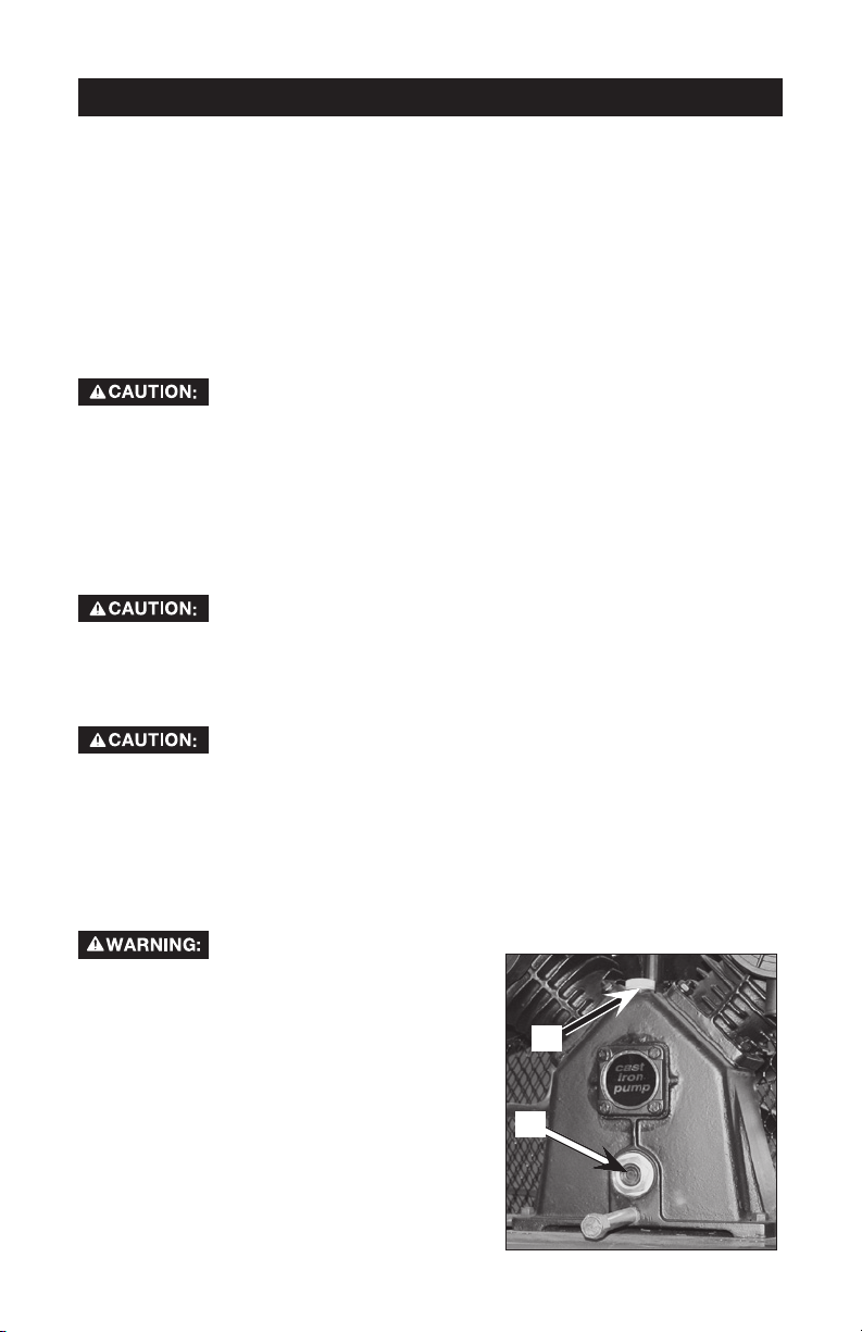
1. Place unit on a level surface.
2. Remove oil fill plug (A) and slowly add a
compressor oil to the middle of sight
glass (B). NOTE: When filling the
crankcase, the oil flows very slowly into
the pump. If the oil is added too quickly,
it will overflow and appear to be full.
NOTE: Crankcase oil capacity is
approximately 48 fluid ounces.
3. Replace oil fill plug.
outfit when removing the pallet because the air compressor
Compressors are shipped with some oil due to factory
testing. Do not operate this air compressor without adding
Multi-Viscosity motor oils, like 10W30, should not be used
in an air compressor. They leave carbon deposits on critical
Drain tank to release air pressure before removing the oil fill
cap or oil drain plug.
A
B
9-ENG A18791
Page 10
INSTALLATION
HOW TO SET UP YOUR UNIT
Location of the Air Compressor
• Locate the air compressor in a clean, dry, and well ventilated area.
• Located the air compressor at least 12" away from the wall or other
obstructions that will interfere with the flow of air.
• Locate the air compressor as close to the main power supply as possible
to avoid using long lengths of electrical wiring. NOTE: Long lengths of
electrical wiring could cause power loss to the motor.
• The air filter must be kept clear of obstructions which could reduce air flow
to the air compressor.
Anchoring of the Air Compressor
Risk of Bursting. Excessive Vibration can weaken the air
properly mounted.
The air compressor MUST be bolted to a solid, level surface.
Hardware needed:
4 - Concrete anchors (not supplied)
4 - 3/8" Lag screw to fit concrete anchors
4 - 5/8" Washer (supplied)
shims (if needed)
1. Place the air compressor on a solid, level surface.
2. Mark the surface using the holes in the air compressor feet as a template.
3. Drill holes in the surface for the concrete anchors. Install concrete anchors.
4. Line-up holes in surface with holes in air compressor feet.
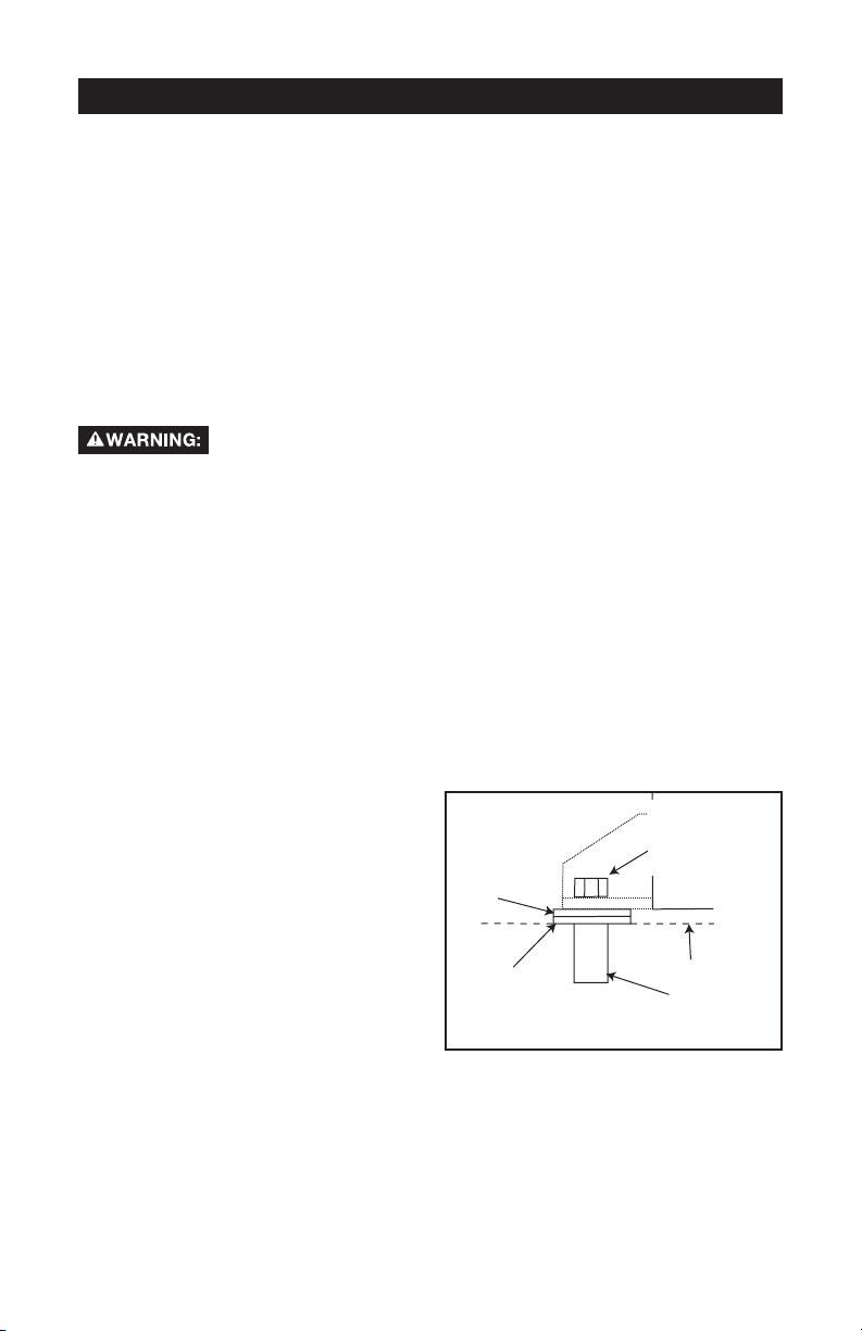
5. Place the (4) washers (supplied)
between the floor and air
compressor feet. If needed, solid
shims may be placed between the
washers and floor to evenly
distribute weight on all four feet.
See next figure.
6. Place the (4) 3/8" lag screws
through the air compressor feet,
washers, shims, and into the
anchors.
7. Torque 3/8" lag screws to 7-10 ft.-lbs.
tank and cause an explosion. The compressor must be
(not supplied)
5/8" Washer
(supplied)
Shim Under
Washer
(not supplied)
3/8" Lag
Screw
(not supplied)
Surface Line
Concrete Anchor
(not supplied)
10-ENGA18791
Page 11

Wiring Instructions
Risk of Electrical Shock. Improper electrical grounding can
result in electrical shock. The wiring should be done by a
qualified electrician
A qualified electrician needs to knows the following before wiring:
1. The amperage rating of the electrical box should be adequate. Refer to the
Specification Chart, in the parts manual, for this information.
2. The supply line should have the same electrical characteristics (voltage,
cycle, phase) as the motor. Refer to the motor nameplate, on side of motor,
for this information.
NOTE: The wiring must be the same as the motor nameplate voltage plus or
minus 10%. Refer to local codes for recommended wire sizes, correct wire size,
and maximum wire run; undersize wire causes high amp draw and overheating
to the motor.
Risk of Electrical Shock. Electrical wiring must be located
away from hot surfaces such as manifold assembly,
compressor outlet tubes, heads, or cylinders.
GROUNDING INSTRUCTIONS
This product should be connected to a metallic, permanent wiring system, of an
equipment-grounding terminal or lead on the product.
Voltage and Circuit Protection
Refer to the specification chart for the voltage and minimum branch circuit
requirements.
11-ENG A18791
Page 12
Air Distribution System
Risk of Bursting. Plastic or PVC pipe is not designed for use
rating, plastic pipe can burst from air pressure. Use only metal pipe for air
distribution lines.
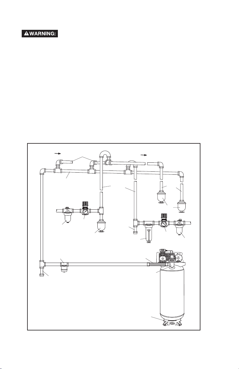
The next figure represents a typical air distribution system. The following are
tips to remember when setting up the air compressor’s air distribution system.
• Use pipe that is the same size as the air tank outlet. Piping that is too small
will restrict the flow of air.
• If piping is over 100 feet long, use the next larger size.
• Bury underground lines below the frost line and avoid pockets where
condensation can gather and freeze. Apply pressure before underground
lines are covered to make sure all pipe joints are free of leaks.
• A flexible coupling is recommended to be installed between the air
discharge outlet and main air distribution line to allow for vibration.
• A separate regulator is recommended to control the air pressure. Air
pressure from the tank is usually to high for individual air driven tools.
AIR FLOW
with compressed air. Regardless of its indicated pressure
FEEDER LINES SLOPE
WITH AIR FLOW
MAIN DISTRIBUTION AIR LINES
Slope pipe in direction of air flow.
Water condensate flows along
bottom of pipe to drain legs,
preventing it from entering feeder
lines.
AIR USAGE
LINES
AIR FLOW
DRAIN
LEGS
LUBRICATOR
MOISTURE
SEPARATOR
AND TRAP
DIRT
LEG
REGULATOR
DRAIN
TRAP
TYPICAL COMPRESSED
AIR DISTRIBUTION SYSTEM
12-ENGA18791
DIRT
LEG
FILTER
FLEXIBLE
COUPLING
AIR DISCHARGE
DRAIN COCK
VALVE
VALVE
DRAIN
TRAPS
REGULATOR
COMPRESSOR
LUBRICATOR
AIR
Page 13
OPERATION
Know Your Air Compressor
READ THIS OWNER’S MANUAL AND SAFETY RULES BEFORE OPERATING
YOUR UNIT. Compare the illustrations with your unit to familiarize yourself with
the location of various controls and adjustments. Save this manual for future
reference.
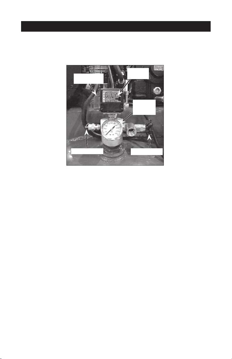
Pressure
On/Auto/Off
Switch
Switch
Tank
Pressure
Gauge
Safety Valve
Globe Valve
Description of Operation
Become familiar with these controls before operating the unit.
On/Auto/Off Lever: Turn this switch "On/Auto" to provide automatic power to
the pressure switch and "Off" to remove power at the end of each use.
Pressure Switch: The pressure switch automatically starts the motor when the
air tank pressure drops below the factory set "cut-in" pressure. It stops the motor when the air tank pressure reaches the factory set "cut-out" pressure.
Safety Valve: If the pressure switch does not shut off the air compressor at its
"cut-out" pressure setting, the safety valve will protect against high pressure by
"popping out" at its factory set pressure (slightly higher than the pressure switch
"cut-out" setting).
Tank Pressure Gauge: The tank pressure gauge indicates the reserve air pressure in the tank.
Globe Valve (sold separately): Opens and closes air discharge valve. Turn knob
counter-clockwise to open and clockwise to close.
Regulator (sold separately, not shown): An air pressure regulator or a separate
air transformer which combines the functions of air regulation and/or moisture
and dirt removal is recommended for most applications.
Cooling System (not shown): This compressor contains an advanced design
cooling system. At the heart of this cooling system is an engineered fan. It is
perfectly normal for this fan to blow air through the vent holes in large amounts.
You know that the cooling system is working when air is being expelled.
Air Compressor Pump (not shown): Compresses air into the air tank. Working
air is not available until the compressor has raised the air tank pressure above
that required at the air outlet.
13-ENG A18791
Page 14
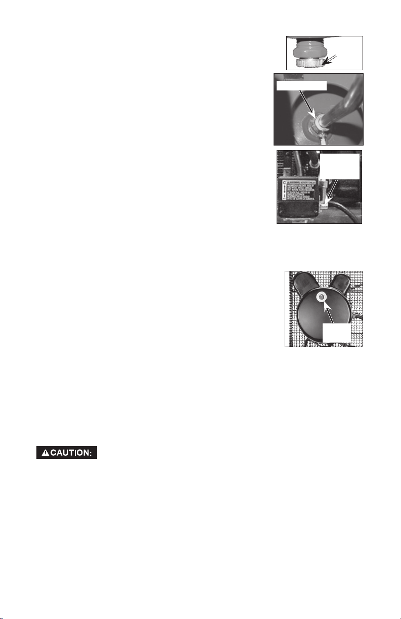
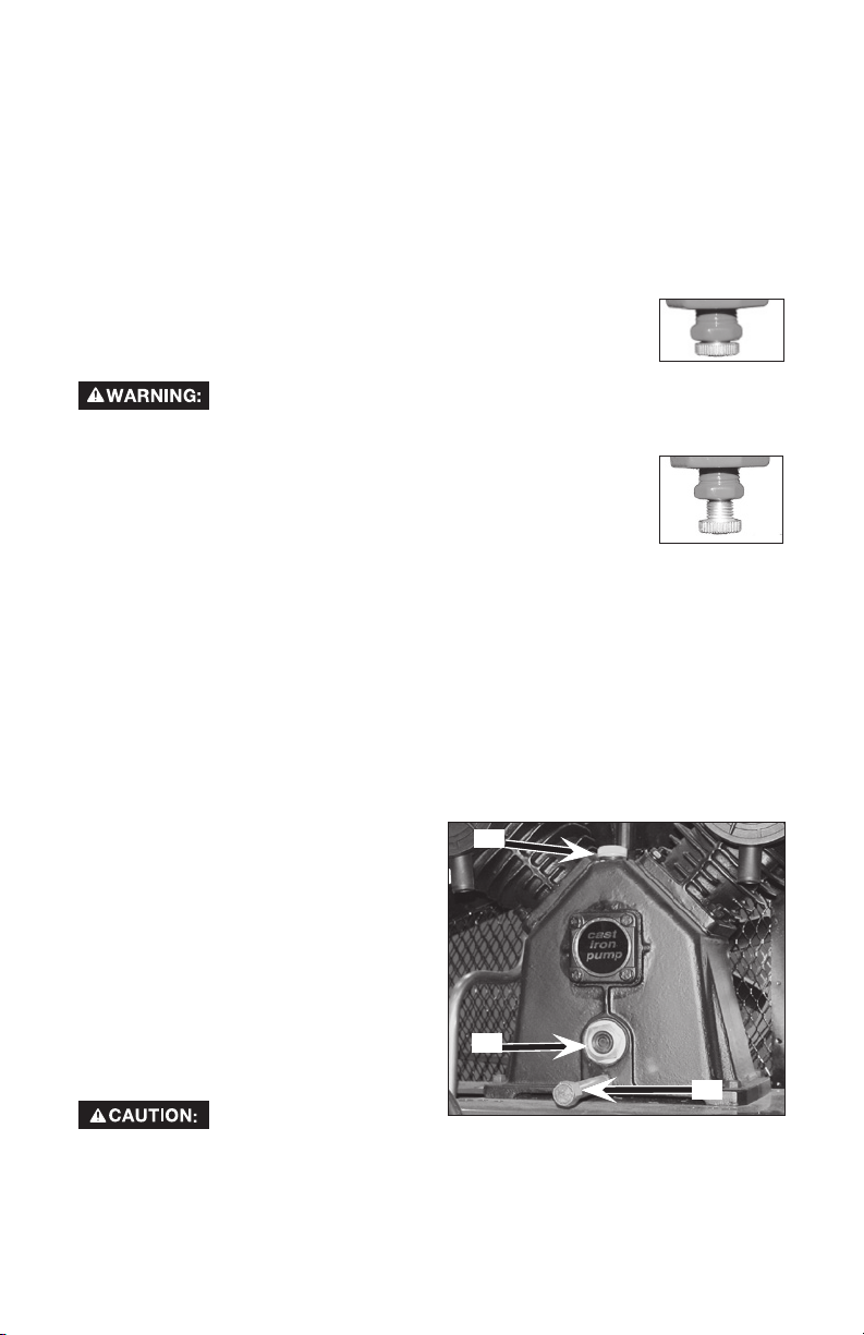
Drain Valve: The drain valve is located at the base of
the air tank and is used to drain condensation at the end of
each use.
Drain
Valve
Check Valve: When the air compressor is operating, the
check valve is "open", allowing compressed air to enter
the air tank. When the air compressor reaches "cut-
Check Valve
out" pressure, the check valve "closes", allowing air
pressure to remain inside the air tank.
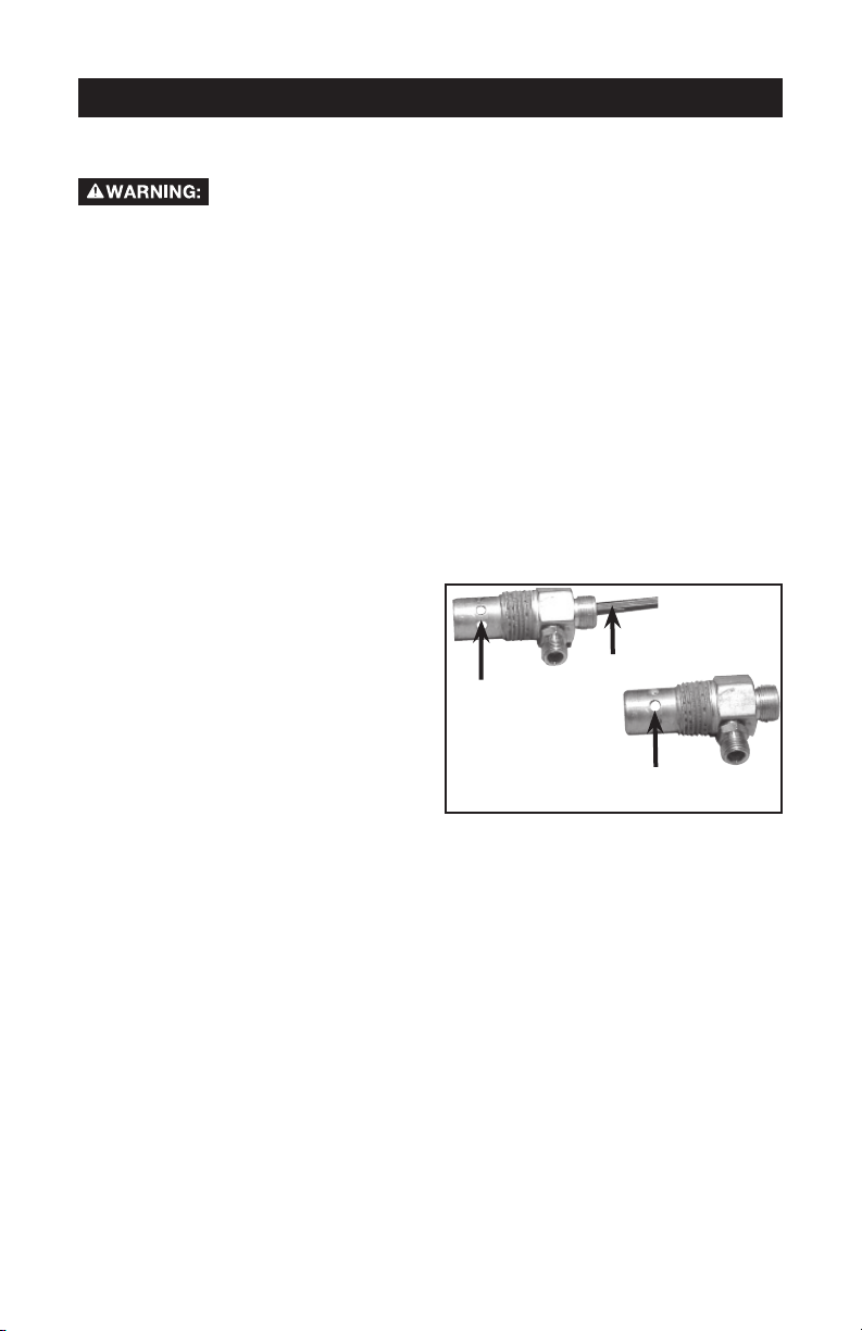
Pressure Release Valve: The pressure release valve
located on the side of the pressure switch, is designed
to automatically release compressed air from the
compressor head and the outlet tube when the air
compressor reaches "cut-out" pressure or is shut off. The
pressure release valve allows the motor to restart freely.
Pressure
Release
Valve
When the motor stops running, air will be heard escaping
from this valve for a few seconds. No air should be heard
leaking when the motor is running or after the unit
reaches "cut-out" pressure.
Motor Overload Protector: This motor has a manual
thermal overload protector. If the motor overheats for any reason, the overload
protector will shut off the motor. The motor must be allowed to cool down before restarting. To restart:
1. Place the On/Auto/Off lever in the "Off" position.
2. Allow the motor to cool.
3. Depress the red reset button on the motor.
4. Place the On/Auto/Off lever in the "On/Auto" postion to
restart the motor.
Air Intake Filter (not shown): This filter is designed to
Reset
Button
clean air coming into the pump. This filter must always be
clean and ventilation openings free from obstructions. See "Maintenance".
How to Use Your Unit
How to Stop:
1. Set the On/Auto/Off lever to "Off".
Before Starting
Break-in Procedure
Risk of Unsafe Operation. Serious damage may result if the
following break-in instructions are not closely followed.
This procedure is required before the air compressor is put into service and
when the check valve or a complete compressor pump has been replaced.
1. Make sure the On/Auto/Off lever is in the "Off" position.
2. Check oil level in pump. See "Oil" paragraph in the Maintenance section for
instructions.
3.
Recheck all wiring. Make sure wires are secure at all terminals connections.
Make sure all contacts move freely and are not obstructed.
4. Open the globe valve fully to permit air to escape and prevent air pressure
build up in the air tank during the break-in period.
5. Move the On/Auto/Off lever to "On/Auto" position. The compressor will start.
14-ENGA18791
Page 15

6. Run the compressor for 20 minutes. Make sure the globe valve is open and
there is minimal air pressure build-up in tank.
7. Check all air line fittings and connections/piping for air leaks by applying a
soap solution. Correct if necessary. NOTE: Minor leaks can cause the air
compressor to overwork, resulting in premature breakdown or inadequate
performance.
8. Check for excessive vibration. Readjust or shim air compressor feet, if necessary.
9. After 20 minutes, close the globe valve. The air receiver will fill to "cut-out"
pressure and the motor will stop.
Before Each Start-Up:
1. Place On/Auto/Off lever to "Off".
2. Close the globe valve.
3. Attach hose and accessories. NOTE: A regulator MUST be installed when
using accessories rated at less than 175 PSI.
NOTE: The hose or accessory will require a quick connect plug if the air outlet
is equipped with a quick connect socket.
Risk of Bursting. Too much air pressure causes a hazard-
ous risk of bursting. Check the manufacturer’s maximum
pressure rating for air tools and accessories. The regulator outlet pressure
must never exceed.
How to Start:
1. Turn the On/Auto/Off lever to "On/Auto" and allow tank pressure to build.
Motor will stop when tank pressure reaches "cut-out" pressure.
2. When the tank pressure reaches "cut-out" pressure open the globe valve.
IMPORTANT: When using regulator and other accessories refer to the manufac-
turers instructions.
The compressor is ready for use.
15-ENG A18791
Page 16
MAINTENANCE
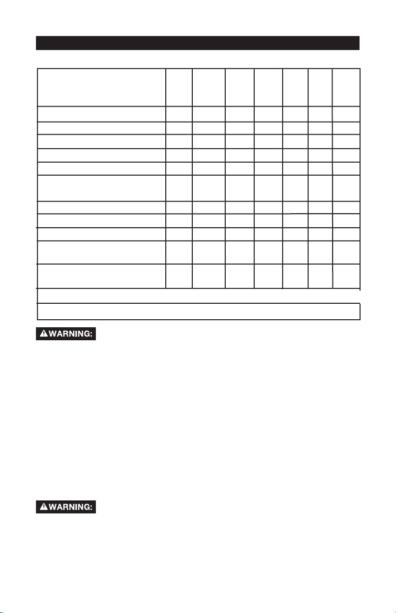
Customer Responsibilities
Before
each
use
Check Safety Valve
Drain Tank
Oil Leaks
Check Oil
Daily
or after
each
use
Every
8
hours
●
●
●
●
Change Oil
Unusual Noise and/or
Vibration
●
Air Filter
Drive Belt-Condition
Motor Pulley/Flywheel alignment
Air compressor pump intake
and exhaust valves
Inspect air lines and fittings
for leaks
●
Head Bolts - Check the torques of the head bolts after the first five hours of operation.
1- more frequent in dusty or humid conditions
Risk of Unsafe Operation. Unit cycles automatically when
power is on. When servicing, you may be exposed to voltage sources, compressed air, or moving parts. Before servicing unit unplug
or disconnect electrical supply to the air compressor, bleed tank of pressure, and allow the air compressor to cool.
To ensure efficient operation and longer life of the air compressor, a routine
maintenance schedule should be prepared and followed. The above routine
maintenance schedule is geared to an air compressor in a normal working
environment operating on a daily basis. If necessary, the schedule should be
modified to suit the conditions under which your air compressor is used. The
modifications will depend upon the hours of operation and the working environment. Compressors in an extremely dirty and/or hostile environment will require
a greater frequency of all maintenance checks.
NOTE: See Operation section for the location of controls.
Every
40
hours
●
Every
100
hours
1
●
●
Every
160
hours
●
Yearly
●
To Check Safety Valve
Risk of Bursting. If the safety valve does not work properly,
over-pressurization may occur, causing air tank rupture or
an explosion.
1. Before starting compressor, pull the ring on the safety valve to make sure
that the safety valve operates freely. If the valve is stuck or does not operate
smoothly, it must be replaced with the same type of valve.
16-ENGA18791
Page 17
Drain Tank
NOTE: Operation of the air compressor will cause condensation to build up in
the air tank. Always drain tank on a washable surface or in a suitable container
to prevent damaging or staining surfaces.
1. Set the On/Auto/Off lever to "Off".
2. Close the globe valve.
3. Remove the air tool or accessory.
4. Open the globe valve and allow the air to slowly bleed from the air tank until
tank pressure is approximately 20 psi.
5. Close the globe valve.
6. Drain water from air tank by opening drain valve on bottom
of tank.
Risk of Bursting. Water will condense in the
Open Drain
Valve
air tank. If not drained, water will corrode
and weaken the air tank causing a risk of air tank rupture.
7. After the water has been drained, close the drain valve. The
air compressor can now be stored.
NOTE: If drain valve is plugged, release all air pressure. The valve
can then be removed, cleaned, then reinstalled.
Closed Drain
Valve
Oil
NOTE: Use an oil specifically formulated for use in an air compressor, such as
Porter-Cable PAS1 air compressor oil. Oil may be found at the store where the
air compressor was purchased.
NOTE: Crankcase oil capacity is approximately 48 fluid ounces (1.4 L).
Checking
1. The oil level should be to the middle of the sight glass (C).
2. If needed remove oil fill plug (A) and slowly add oil until it reaches the
middle of the sight glass.
Changing
1. Remove the oil fill plug (A).
2. Remove the oil drain plug (B) and
drain oil into a suitable container.
3. Replace the oil drain plug (B) and
tighten securely.
4. Sowly add compressor oil until
the oil level is in the middle of the
sightglass (C). NOTE: When filling
the crankcase, the oil flows very
slowly into the pump. If the oil is
added too quickly, it will overflow
and appear to be full.
Risk of Unsafe Operation. Overfilling with oil
will cause premature compressor failure. Do not overfill.
5. Replace oil fill plug (A) and tighten securely.
A
C
B
17-ENG A18791
Page 18
Air Filter - Inspection and Replacement
Hot surfaces. Risk of burn. Compressor heads are exposed
to servicing.
A dirty air filter will not allow the compressor to operate at full capacity. Keep the
air filter clean at all times.
1. Remove air filter.
2. Remove the air filter cover.
3. Remove the air filter from filter cover.
IMPORTANT: Do not operate the compressor with the air filter removed.
4. Place new air filter into filter cover. Refer to the Repair Parts for the correct
part number.
5. Replace air filter cover and reassemble air filter to pump.
when filter cover is removed. Allow compressor to cool prior
Keep the air filter clean at all times. Do not operate the air
compressor with the air filter removed.
Belt - Replacement
(Refer to the Parts Manual for replacement belt part number.)
Serious injury or damage may occur if parts of the body or
outfit with the belt guard removed. The belt guard should be removed only
when the air compressor power is disconnected.
1. Turn air compressor off, lock out the power supply, and relieve all air pres-
sure from the air tank.
2. Remove the belt guard.
3. Mark pump position on saddle.
4. Loosen the motor mounting screws and slide the motor toward the air com-
pressor.
5. Remove the belt and replace with a new one.
6. See the "Adjust Belt Tension" before tightening motor mounting screws.
loose items get caught in moving parts. Never operate the
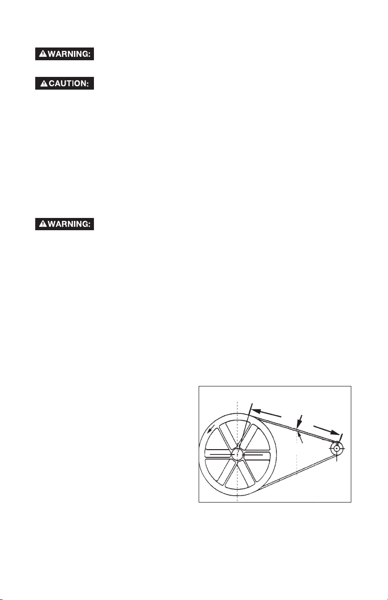
Adjusting Belt Tension
1. Slide motor into original position, line the motor up with the mark made
earlier on saddle.
2. Tighten two outside motor mounting screws enough to hold the motor in
place for checking pulley and
flywheel alignment.
3. The belt should deflect 3/16" at
midway between the pulley and
the flywheel when a 5-10 pound
weight is applied at the midway
point.
4. When proper belt tension is
achieved, tighten all four motor mounting screws. See Parts
manual for torque specifications.
Downward Force
Deflection
18-ENGA18791
Page 19
NOTE: Once the engine pulley has been moved from its factory set location,
the grooves of the flywheel and pulley must be aligned to within 1/16" to
prevent excessive belt wear. Verify the alignment by performing the following Pulley and Flywheel - Alignment.
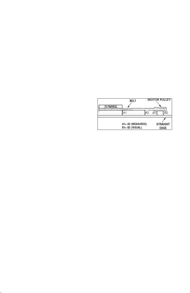
Motor Pulley/Flywheel Alignment
NOTE: Once the motor pulley has been moved from its factory set location, the
grooves of the flywheel and pulley must be aligned to within 1/16" to prevent
excessive belt wear.
The air compressor flywheel and motor pulley must be in-line (in the same plane)
within 1/16" to assure belt retention within flywheel belt grooves. To check
alignment, perform the following steps:
1. Turn air compressor off, lock out the power supply, and relieve all air
pressure from the air tank.
2. Remove belt guard.
3. Place a straightedge against the outside of the flywheel and the motor
drive pulley.
4. Measure the distance between
the edge of the belt and the
straightedge at points A1 and A2
in figure. The difference between
measurements should be no more
than 1/16".
5. If the difference is greater than 1/16"
loosen the set screw holding the motor drive pulley to the shaft and adjust
the pulley’s position on the shaft until the A1 and A2 measurements are
within 1/16" of each other.
6. Tighten the motor drive pulley set screw. See Parts manual for torque
specifications.
7. Visually inspect the motor drive pulley to verify that it is perpendicular to
the drive motor shaft. Points B1 and B2 of Figure should appear to be
equal. If they are not, loosen the setscrew of the motor drive pulley and
equalize B1 and B2, using care not to disturb the belt alignment performed
in step 2.
8. Retighten the motor drive pulley setscrew. See Parts manual for torque
specifications.
Air Compressor Pump Intake and Exhaust Valves
Once a year have a Trained Service Technician check the air compressor pump
intake and exhaust valves.
Inspect Air Lines and Fittings for Leaks
1. Turn air compressor off, lock out the power supply, and relieve all air
pressure from the air tank.
2. Apply a soap solution to all air line fittings and connections/piping.
3. Correct any leaks found.
IMPORTANT: Even minor leaks can cause the air compressor to overwork,
resulting in premature breakdown or inadequate performance.
Air compressor Head Bolts - Torquing
The air compressor pump head bolts should be kept properly torqued. Check
the torques of the head bolts after the first five hours of operation. Retighten if
necessary. See Parts manual for torque specifications
19-ENG A18791
Page 20
SERVICE AND ADJUSTMENTS
ALL MAINTENANCE AND REPAIR OPERATIONS NOT LISTED MUST BE
PERFORMED BY TRAINED SERVICE TECHNICIAN.
Risk of Unsafe Operation. Unit cycles automatically when
sources, compressed air, or moving parts. Before servicing unit unplug or
disconnect electrical supply to the air compressor, bleed tank of pressure,
and allow the air compressor to cool.
To Replace or Clean Check Valve
1. Release all air pressure from air tank. See "To Drain Tank" in the
Maintenance section.
2. Turn air compressor off, lock out the power supply, and relieve all air
pressure from the air tank.
3. Using an adjustable wrench loosen outlet tube nut at air tank and pump.
Carefully move outlet tube away from check valve.
4. Using an adjustable wrench loosen pressure relief tube nut at air tank and
pressure switch. Carefully move pressure relief tube away from check
valve.
5. Unscrew the check valve (turn counterclockwise) using a 7/8" open end
wrench. Note the orientation for reassembly.
6. Using a screwdriver, carefully push
the valve disc up and down.
NOTE: The valve disc should
move freely up and down on a
spring which holds the valve disc
in the closed position, if not the
check valve needs to be cleaned
or replaced.
7. Clean or replace the check valve.
A solvent, such as paint or varnish
remover can be used to clean the
check valve.
8. Apply sealant to the check valve threads. Reinstall the check valve (turn
clockwise).
9. Replace the pressure release tube. Tighten nuts.
10. Replace the outlet tube and tighten nuts.
11. Perform the Break-in Procedure. See "Break-in Procedure" in the Operation
section.
Additional Service
Disassembly or service of the air compressor beyond what is covered in this
manual is not recommended. If additional service is required, contact your nearest Authorized Warranty
power is on. When servicing, you may be exposed to voltage
Screwdriver
In open
position
nothing is
visible.
In closed position
disc is visible.
20-ENGA18791
Page 21

STORAGE
Before you store the air compressor, make sure you do the following:
1. Review the Maintenance section on the preceding pages and perform
scheduled maintenance as necessary.
2. Set the On/Auto/Off lever to "Off".
3. Close the globe valve.
4. Remove the air tool or accessory.
5. Open the globe valve and allow the air to slowly bleed from the air tank
until tank pressure is approximately 20 psi.
6. Drain water from air tank by opening drain valve on bottom of tank.
Water will condense in the air tank. If not drained, water will
rupture.
7. After the water has been drained, close the drain or drain valve.
NOTE: If drain valve is plugged, release all air pressure. The valve can then be
removed, cleaned, then reinstalled.
8. Protect the air hose from damage (such as being stepped on or run over).
corrode and weaken the air tank causing a risk of air tank
21-ENG A18791
Page 22
TROUBLESHOOTING
Performing repairs may expose voltage sources, moving
Prior to attempting any repairs, unplug the air compressor and bleed off all
air tank air pressure.
parts or compressed air sources. Personal injury may occur.
PROBLEM
Excessive
tank pressure
- safety valve
pops off.
Air leaks at
fittings.
Air leaks at or
inside check
valve.
Air leaks at
pressure switch
release valve.
CAUSE
Pressure switch does not
shut off motor when compressor reaches "cut-out"
pressure.
Pressure switch "cut-out"
too high.
Tube fittings are not tight
enough.
Check valve seat damaged.
Defective pressure switch
release valve.
CORRECTION
Move On/Auto/Off lever to
the "Off" position, if the unit
does not shut off contact a
Trained Service Technician.
Contact a Trained Service
Technician.
Tighten fittings where air can
be heard escaping. Check fittings with soapy water solution. DO NOT OVER TIGHTEN.
A defective check valve
results in a constant air leak
at the pressure release valve
when there is pressure in the
tank and the compressor
is shut off. Replace check
valve. Refer the "To Replace
or Clean Check Valve" in the
Service and Adjustments
section.
Contact a Trained Service
Technician.
Air leaks in air
tank or at air
tank welds.
Air leaks between head and
valve plate.
Defective air tank.
Leaking seal.
Air tank must be replaced.
Do not repair the leak.
Do not drill
into, weld or
otherwise modify air tank
or it will weaken. The tank
can rupture or explode.
Contact a Trained Service
Technician.
22-ENGA18791
Page 23
PROBLEM
Pressure reading
on the regulated
pressure gauge
(if equipped)
drops when an
accessory is
used.
Air leak from
safety valve.
CAUSE
It is normal for "some"
pressure drop to occur.
Possible defect in safety
valve.
CORRECTION
If there is an excessive amount
of pressure drop when the
accessory is used, adjust the
regulator as instructed in the
Operation section.
NOTE: Adjust the regulated
pressure under flow conditions (while accessory is being
used).
Operate safety valve manually
by pulling on ring. If valve still
leaks, it should be replaced.
Compressor is
not supplying
enough air to
operate accessories.
Restricted air
intake.
Prolonged excessive use
of air.
Compressor is not large
enough for air requirement.
Hole in hose.
Check valve restricted.
Air leaks.
Restricted air intake filter.
Loose belt.
Dirty air filter.
Decrease amount of air usage.
Check the accessory air requirement. If it is higher than
the SCFM or pressure supplied
by your air compressor, you
need a larger compressor.
Check and replace if required.
Remove and clean, or replace.
Tighten fittings.
Clean or replace air intake
filter. Do not operate the air
compressor with the filter removed. Refer to the "Air Filter"
paragraph in the Maintenance
section.
Check belt tension, see Adjusting Belt Tension in the Maintenance section.
Clean or replace. See Air Filter
paragraph in the Maintenance
section.
23-ENG A18791
Page 24
PROBLEM
Motor will not
run.
CAUSE
Motor overload protection
switch has tripped.
Tank pressure exceeds
pressure switch "cut-in"
pressure.
Check valve stuck open.
CORRECTION
Let motor cool off and
overload switch will
automatically reset.
Motor will start automatically
when tank pressure drops
below "cut-in" pressure of
pressure switch.
Remove and clean, or replace.
Loose electrical
connections.
Possible defective motor
or starting capacitor.
Paint spray on internal
motor parts.
Pressure release valve on
pressure switch has not
unloaded head pressure.
Fuse blown, circuit breaker
tripped.
Check wiring connection
inside pressure switch and
terminal box area.
Have checked by a Trained
Service Technician.
Have checked by a Trained
Service Technician. Do not
operate the compressor in
the paint spray area. See
flammable vapor warning.
Bleed the line by pushing the
lever on the pressure switch to
the "Off" position; if the valve
does not open, replace switch.
1. Check fuse box for blown
fuse and replace as
necessary. Reset circuit
breaker. Do not use a
fuse or circuit breaker
with higher rating than
that specified for your
particular branch circuit.
2. Check for proper fuse. You
should use a time delay
fuse.
3. Check for low voltage
conditions and/or proper
extension cord.
4. Disconnect the other
electrical appliances from
circuit or operate the
compressor on its own
branch circuit.
Safety Valve
on pump
"pops" out (if
equipped).
Pressure switch, check
valve, or pump could be
in need of servicing.
24-ENGA18791
Have checked by a Trained
Service Technician.
Page 25
PROBLEM
CAUSE
CORRECTION
Knocking Noise.
Excessive belt
wear.
Possible defect in safety
valve.
Defective check valve. Remove and clean, or replace.
Loose pulley. Tighten pulley set screw, see
Loose flywheel. Tighten flywheel screw, see
Compressor mounting
screws loose.
Loose belt.
Carbon build-up in pump. Have checked by a Trained
Belt to tight. Check belt tension, see "Ad-
Loose belt.
Operate safety valve manually
by pulling on ring. If valve still
leaks, it should be replaced.
Parts manual for torque specifications.
Parts manual for torque specifications.
Tighten mounting screws,see
Parts manual for torque specifications.
Check belt tension, see "Adjusting Belt Tension" in the
Maintenance section.
Service Technician.
justing Belt Tension" in the
Maintenance section.
Check belt tension, see "Adjusting Belt Tension" in the
Maintenance section.
Squealing
sound.
Tight belt.
Loose pulley.
Pulley misalignment.
Compressor pump has no
oil.
Loose belt.
25-ENG A18791
Check belt tension, see "Adjusting Belt Tension" in the
Maintenance section.
Have checked by a Trained
Service Technician.
See "Motor Pulley/Flywheel
Alignment" paragraph in the
Maintenance section.
See Oil-Checking paragraph in
the Maintenance section.
Check belt tension, see "Adjusting Belt Tension" in the
Maintenance section.
Page 26

LIMITED WARRANTY
DeVilbiss Air Power Company warrants to the original purchaser who uses the product in a
consumer application (personal, residential or household usage) that all products covered under this
warranty are free from defects in material and workmanship for one year from the date of purchase.
All products covered by this limited warranty which are used in commercial applications (i.e., income
producing) are warranted to be free of defects in material and workmanship for 90 days from the date
of original purchase. Products covered under this warranty include air compressors, air tools, service
parts, pressure washers, and generators.
DeVilbiss Air Power Company will repair or replace, at DeVilbiss' option, products or components
which have failed within the warranty period. Service will be scheduled according to the normal work
flow and business hours at the service center location, and the availability of replacement parts. All
decisions of DeVilbiss Air Power Company with regard to this limited warranty shall be final.
This warranty gives you specific legal rights, and you may also have other rights which vary from state
to state.
RESPONSIBILITY OF ORIGINAL PURCHASER (initial User):
• To process a warranty claim on this product, DO NOT return it to the retailer. The product must be
evaluated by an Authorized Warranty Service Center. For the location of the nearest Authorized
Warranty Service Center call 1-800-888-2468, 24 hours a day, 7 days a week or visit our web site
@ devap.com.
• Retain original cash register sales receipt as proof of purchase for warranty work.
• Use reasonable care in the operation and maintenance of the product as described in the Owners
Manual(s).
• Deliver or ship the product to the nearest Authorized Warranty Service Center. Freight costs, if any,
must be paid by the purchaser.
• Air compressors with 60 and 80 gallon tanks will be inspected at the site of installation. Contact
the nearest Authorized Warranty Service Center that provides on-site service calls for service call
arrangements.
• If the purchaser does not receive satisfactory results from the Authorized Warranty Service Center,
the purchaser should contact DeVilbiss Air Power Company.
THIS WARRANTY DOES NOT COVER:
• Merchandise sold as reconditioned, used as rental equipment, or floor or display models.
• Merchandise that has become damaged or inoperative because of ordinary wear, misuse*, cold,
heat, rain, excessive humidity, freeze damage, use of improper chemicals, negligence, accident,
failure to operate the product in accordance with the instructions provided in the Owners Manual(s)
supplied with the product, improper maintenance, the use of accessories or attachments not
recommended by DeVilbiss Air Power Company, or unauthorized repair or alterations.
* An air compressor that pumps air more than the recommended duty cycle during a one hour
period may be considered misuse.
• Repair and transportation costs of merchandise determined not to be defective.
• Costs associated with assembly, required oil, adjustments or other installation and start-up costs.
• Expendable parts or accessories supplied with the product which are expected to become
inoperative or unuseable after a reasonable period of use, including but not limited to sanding disks
or pads, saw and shear blades, grinding stones, springs, chisels, nozzles, o-rings, air jets, washers
and similar accessories.
• Merchandise sold by DeVilbiss Air Power Company which has been manufactured by and identified
as the product of another company, such as gasoline engines. The product manufacturer's
warranty, if any, will apply.
• ANY INCIDENTAL, INDIRECT OR CONSEQUENTIAL LOSS, DAMAGE, OR EXPENSE THAT
MAY RESULT FROM ANY DEFECT, FAILURE OR MALFUNCTION OF THE PRODUCT IS
NOT COVERED BY THIS WARRANTY. Some states do not allow the exclusion or limitation of
incidental or consequential damages, so the above limitation or exclusion may not apply to you.
• IMPLIED WARRANTIES, INCLUDING THOSE OF MERCHANTABILITY OR FITNESS FOR
A PARTICULAR PURPOSE, ARE LIMITED TO ONE YEAR FROM THE DATE OF ORIGINAL
PURCHASE. Some states do not allow limitations on how long an implied warranty lasts, so the
above limitations may not apply to you.
213 Industrial Drive • Jackson, TN 38301-9615
Telephone: 1-800-888-2468
FAX: 1-800-888-9036
26-ENGA18791
Page 27

TABLE DES MATIÈREs
Mesures de sécurité/Définitions ....................27
Mesures de sécurité importantes ...........27-32
Specification ...................................................33
Lexique ...........................................................33
Cycle de Service ............................................33
Accessoires ....................................................33
Assemblage ....................................................34
Installation ................................................. 35-37
Utilisation .................................................. 38-40
Entretien .................................................... 41-44
Entretien Et Réglages ....................................45
Rangement .....................................................46
Dépannage ............................................... 47-50
Notes ...............................................................51
Garantie ..........................................................52
English ........................................................1-26
Español ..................................................... 53-78
MESURES DE SÉCURITÉ - DÉFINITIONS
Ce guide contient des renseignements importants que vous deviez bien saisir. Cette
information porte sur VOTRE SÉCURITÉ et sur LA PRÉVENTION DE PROBLÈMES
D'ÉQUIPEMENT. Afin de vous aider à identifier cette information, nous avons utilisé
les symboles ci-dessous. Veuillez lire attentivement ce guide en portant une attention
particulière à ces symboles.
Indique un danger
imminent qui, s'il n'est
pas évité, causera de graves blessures
ou la mort.
Indique la
possibilité
d’un danger qui, s’il n’est pas évité,
pourrait causer de graves blessures ou
la mort.
danger qui, s'il n'est pas évité, peut
causer des blessures mineures ou
moyennes.
possibilité d’un danger qui, s’il n’est pas
évité, peut causer des dommages à la
propriété.
Indique la
possibilité d'un
Sans le symbole
d’alerte. Indique la
CONSIGNES DE SÉCURITÉ IMPORTANTES
La poussière produite par le ponçage électrique, le sciage,
peut contenir des produits chimiques qui sont reconnus, par l'état de la Californie,
de causer le cancer, les anomalies congénitales ou autres maux de reproduction.
Ces produits chimiques comprennent, entre autres :
• le plomb provenant des peintures à base de plomb;
• la silice cristalline provenant de briques, de béton ou d'autres produits
de maçonnerie
• l'arsenic et le chrome provenant du bois de charpente traité
chimiquement
Le risque d'exposition à ces produits dépend de la fréquence d'exécution de
ce genre de travaux. Afin de réduire l'exposition à ces produits chimiques,
travaillez dans un endroit bien aéré et utilisez de l'équipement de sécurité
approuvé, portez toujours un masque facial ou respirateur homologué MSHA/NIOSH
bien ajusté lorsque vous utilisez de tels outils.
Lorsque vous utilisez un outil pneumatique, il faut toujours suivre les mesures de sécurité
de base afin de réduire le risque de blessures corporelles.
le meulage, le perçage et autres activités de construction
27-FR A18791
Page 28

MESURES DE SÉCURITÉ - DÉFINITIONS
Conserver ces directives
Un emploi ou un entretien non appropriés de ce produit peut causer des blessures graves
et des dommages à la propriété. Lire attentivement tous les avertissements et les directives d'utilisation avant d'utiliser cet appareil.
DANGER
AVERTISSEMENT : Risque d'explosion ou d'incendie
Risque
Les étincelles qui proviennent des contacts
électriques du moteur et du manostat sont
considérées normales.
Si des étincelles électriques du compresseur
entrent en contact avec des vapeurs inflammables, elles peuvent s'enflammer, provoquant un incendie ou une explosion.
Toute obstruction des orifices d'aération du
compresseur entraînera une surchauffe dangereuse et risque de causer un incendie.
Si cet appareil fonctionne sans supervision,
cela risque de causer des blessures graves
ou des dommages à la propriété. Pour réduire
le risque d'incendie, ne jamais laisser le compresseur d'air fonctionner sans supervision.
Prévention
Toujours utiliser le compresseur dans un endroit bien aéré, loin de toute matière combustible et des vapeurs d'essence ou de solvants.
Si des matières inflammables doivent être
vaporisées, situer le compresseur à une
distance d'au moins 20 pieds (6 m) de la zone
de vaporisation. Il peut s'avérer nécessaire
d'utiliser un boyau supplémentaire.
Entreposer les matières inflammables dans
un endroit sécuritaire, loin du compresseur.
Ne jamais placer des objets contre ou sur le
compresseur. Utiliser le compresseur dans un
endroit ouvert, à au moins 12 pouces (30 cm)
de tout mur ou obstruction qui réduit le débit
d'air frais vers les orifices d'aération.
Utiliser le compresseur dans un endroit propre,
sec et bien aéré. Ne pas utiliser l'appareil à
l'intérieur ou dans un endroit clos.
Toujours rester à proximité de l'appareil
lorsqu'il est en fonction.
Toujours couper l'alimentation électrique en
plaçant le levier du manostat à la position
d'arrêt « Off » et vidanger le réservoir chaque
jour ou après chaque usage.
28-FRA18791
Page 29

DANGER
AVERTISSEMENT : Risque d'éclatement
Réservoir d'air : Les conditions suivantes peuvent affaiblir les parois du réservoir et provoquer
une explosion violente du réservoir qui risque de causer des dommages à la propriété ou des
blessures graves.
Risque
Le défaut de vidanger de façon appropriée
l'eau condensée dans le réservoir risque de
causer la rouille et l'amincissement des parois
en acier du réservoir.
Des modifications ou tentatives de réparation
faites sur le réservoir.
Des modifications non autorisées apportées à
la soupape de décharge, à la soupape de
sûreté ou à toute autre composante qui
contrôle la pression du réservoir.
Purger le réservoir quotidiennement ou après
chaque utilisation. Si le réservoir accuse une
fuite, le remplacer immédiatement par un nouveau réservoir ou remplacer le compresseur au
complet.
Ne jamais perforer avec une perceuse, souder
ou faire une modification quelconque au
réservoir ou à ses accessoires.
Prévention
Des vibrations excessives peuvent affaiblir le
réservoir et causer une rupture ou une
explosion.
FIXATIONS ET ACCESSOIRES :
Le fait d'excéder la pression nominale des
outils pneumatiques, pistolets vaporisateurs,
accessoires pneumatiques, pneus et autres
objets gonflables risque de provoquer
l'explosion de ces derniers et la projection
de pièces, ce qui risque de causer de graves
blessures.
DANGER
AVERTISSEMENT : Risque de projection d'objets
Risque
Le jet d'air comprimé peut causer des lésions aux tissus de la peau exposée et peut
projeter de la saleté, des copeaux, des particules libres et de petits objets à haute vitesse,
ce qui risque de causer des dommages à la
propriété ou des blessures.
Le réservoir est conçu pour subir des pressions
de service particulières. Ne jamais effectuer
des réglages ni substituer des pièces pour
modifier les pressions de service établies à
l'usine.
Pour le contrôle essentiel de la pression d'air, il
faut poser un régulateur de pression (s'il n'est
pas déjà posé) et un manomètre à la sortie
d'air du compresseur. Suivre les recommanda-
tions du fabricant de l'équipement et ne jamais
excéder la valeur nominale de pression spécifiée
des accessoires. Ne jamais utiliser le compres-
seur pour gonfler des objets à faible pression,
tels que les jouets d'enfant, les ballons de
football ou de basket-ball, etc.
Prévention
Porter toujours des lunettes de protection
homologuées ANSI Z87.1 avec des écrans
latéraux lors de l'utilisation du compresseur.
Ne jamais diriger la buse ou le vaporisateur
vers soi, vers d'autres personnes ou vers des
animaux.
Toujours mettre le compresseur hors fonction
et purger la pression du boyau d'air et du réser-
voir avant d'entamer l'entretien ou d'attacher des
outils ou accessoires.
29-FR A18791
Page 30

DANGER
AVERTISSEMENT : Risque de choc électrique
Risque
Votre compresseur d'air est alimenté par
électricité. Comme avec tous les appareils
électriques, si l'appareil n'est pas utilisé de
façon appropriée, il peut causer des chocs
électriques.
Toute réparation effectuée par une personne
non qualifiée peut entraîner des blessures
graves ou la mort par électrocution.
Mise à la terre : Le défaut d'établir une mise
à la terre appropriée pour cet appareil peut
entraîner des blessures graves ou la mort
par électrocution. Voir les directives de mise
à la terre.
DANGER
AVERTISSEMENT : Risque par inhalation
Risque
L'air comprimé de votre compresseur d'air
n'est pas sécuritaire pour l'inhalation. Le jet
d'air peut contenir du monoxyde de carbone,
des vapeurs toxiques ou des particules solides
du réservoir. L'inhalation de ces contaminants
peut causer des blessures graves ou la mort.
Prévention
Ne jamais faire fonctionner le compresseur à
l'extérieur lorsqu'il pleut ou dans des conditions humides.
Ne jamais faire fonctionner le compresseur
sans les couvercles de protection ou lorsque
ceux-ci sont endommagés.
Tout câblage électrique ou toute réparation
requis sur cet appareil devrait être effectué par
le personnel d'un centre de service aprèsvente autorisé, conformément aux codes
électriques nationaux et locaux.
S'assurer que le circuit électrique alimentant
le compresseur fournit une mise à la terre
électrique appropriée, une tension appropriée
et une protection adéquate par fusibles.
Prévention
L'air obtenu directement du compresseur ne
devrait jamais être utilisé comme source d'air
pour les être humains. Si l'air produit par ce
compresseur sera utilisé pour la respiration, il
faut installer des filtres appropriés ainsi que
du matériel de sécurité. Les filtres en ligne et
le matériel de sécurité utilisés avec le compres-
seur doivent être dans la mesure de traiter
l'air de façon à ce qu'il réponde à toutes les
normes nationales et locales applicables
avant d'être utilisé pour les êtres humains.
Les matières vaporisées telles que la peinture,
les solvants de peinture, les décapants, les
insecticides et les herbicides contiennent des
vapeurs nocives et toxiques.
Travailler dans un endroit où il y a une bonne
ventilation transversale. Bien lire et respecter
les directives de sécurité indiquées sur
l'étiquette ou la fiche signalétique de la matière
qui est vaporisée. Porter un respirateur
homologué par le NIOSH/MSHA et conçu pour
l'application en question.
30-FRA18791
Page 31

DANGER
AVERTISSEMENT : Risque de brûlures
Risque
Le fait de toucher aux surfaces de métal
exposées telles que la tête du compresseur
ou les tubes de sortie peut causer de graves
brûlures à la peau.
Ne jamais toucher aux pièces de métal exposées du compresseur durant ou immédiate-
ment après le fonctionnement. Le compresseur
demeure chaud pendant plusieurs minutes
après le fonctionnement.
Ne pas tenter d'atteindre les composantes derrière les gardes de protection et ne pas effectuer
de l'entretien avant d'avoir laissé refroidir
l'appareil.
DANGER
AVERTISSEMENT : Risque relié aux pièces mobiles
Risque
Les pièces mobiles telles que la poulie, le
volant-moteur et la courroie peuvent entraîner
des blessures graves si elles entrent en
contact avec une partie du corps ou des
vêtements.
En tentant de faire fonctionner le
compresseur avec des pièces manquantes
ou endommagées, ou de réparer le
compresseur sans les gardes de protection,
on s'expose aux pièces mobiles, ce qui peut
entraîner des blessures graves.
Ne jamais faire fonctionner le compresseur
sans les gardes ou les couvercles ou lorsque
ceux-ci sont endommagés.
Toute réparation requise sur cet appareil devrait
être effectuée par le personnel d'un centre de
service après-vente autorisé.
Prévention
Prévention
AVERTISSEMENT : Risque de chute
Risque
Un compresseur portatif peut tomber d'une
table, d'un établi ou d'un toit. L'impact peut
causer des dommages au compresseur
et des blessures corporelles ou la mort de
l'utilisateur.
DANGER
Prévention
Toujours s'assurer de la stabilité du compresseur avant de le faire fonctionner afin de prévenir
tout mouvement accidentel de l'appareil. Ne
jamais utiliser un compresseur sur un toit ou
dans une position élevée ; utiliser plutôt un
boyau d'air supplémentaire pour atteindre les
endroits élevés.
31-FR A18791
Page 32
DANGER
AVERTISSEMENT : Risque de dommages à la propriété pendant le
transport du compresseur
(incendie, inhalation, dommages aux surfaces du véhicule)
Risque
Des fuites ou des déversements d'huile
peuvent se produire et entraîner des risques
d'incendie, ou des problèmes aux voies respiratoires, des blessures graves ou la mort. Des
fuites d'huile endommagent les tapis, la peinture
et toute autre surface des véhicules ou des
remorques.
Toujours placer le compresseur sur un tapis
de protection pour éviter l'endommagement du
véhicule par des fuites. Retirer le compresseur du
véhicule immédiatement à l'arrivée.
Prévention
DANGER
AVERTISSEMENT : Risque d'une utilisation dangereuse
Risque
Une utilisation dangereuse de votre com-
presseur d'air pourrait causer des blessures
graves ou la mort de l'utilisateur ou d'autres
personnes.
CONSERVER CES DIRECTIVES
Prévention
Lisez attentivement tous les instructions et les
avertissements figurant dans ce guide.
Familiarisez-vous avec le fonctionnement et
les commandes du compresseur d'air.
Gardez les personnes non-autorisées, les ani-
maux de compagnie et les obstacles éloignés de
l'aire de travail.
Gardez les enfants éloignés du compresseur
d'air en tout temps.
N'utilisez pas le produit lorsque vous êtes
fatigué ou sous l'influence d'alcool ou de
drogues. Restez alerte à tout moment.
Ne tentez jamais d'annuler les caractéristiques
de sécurité de ce produit.
Assurez-vous qu'un extincteur d'incendie est
disponible dans l'aire de travail.
N'utilisez pas l'appareil avec des pièces brisées, manquantes ou non autorisées.
32-FRA18791
Page 33

SPECIFICATIONS
Modèle no E7540
Puissance de service 6,0
Tension/monophasée 240V
Exigence minimale du circuit de dérivation 30 a
Genre de fusibles À retardement
Capacité du réservoir d'air (gallons) 80 (302,8 litres)
Pression l'amorçage approx. 140
Pression de rupture approx. 175
pi³/min standard (SCFM) à 100 lb/po2 14,0
pi³/min standard (SCFM) à 175 lb/po2 13,5
LEXIQUE
Veuillez vous familiariser avec ces termes avant d'utiliser l'appareil.
CFM : pieds cubes par minute (pi3/min).
SCFM : pieds cubes par minute (pi3/min) standard. Une unité de mesure de débit d'air.
PSIG: jauge indiquant le nombre de livres par pouce carré (lb/po2). Une unité de mesure de
pression.
Codes de certification : Les produits portant une ou plusieurs des mentions suivantes (UL, CUL,
ETL, CETL) ont été évalués par des laboratoires indépendants de sécurité certifiés par l'OSHA et
répondent aux normes de sécurité applicables des Underwriters Laboratories.
Pression d'amorçage : Lorsque le moteur est arrêté, la pression du réservoir d'air s'abaisse tandis
qu'on continue d'utiliser l'accessoire. Quand la pression du réservoir tombe à un niveau bas réglé à
l'usine, le moteur se remet automatiquement en marche. La basse pression à laquelle le moteur se
remet automatiquement en marche s'appelle la «pression d'amorçage».
Pression de rupture : Lorsqu'on met un compresseur d'air en marche et qu'il commence à
fonctionner, la pression d'air dans le réservoir commence à s'accumuler. La pression monte
et atteint un niveau élevé réglé à l'usine, avant que le moteur ne s'arrête automatiquement,
protégeant ainsi le réservoir d'air d'un taux de pression qui excèderait sa capacité. La haute
pression à laquelle le moteur s'arrête s'appelle la «pression de rupture».
Circuit de dérivation : Le circuit acheminant l'électricité du tableau électrique vers la prise murale.
Verrouillage de la source d'alimentation : Placez un cadenas sur l'interrupteur d'alimentation de
la ligne pour empêcher la mise sous tension par toute autre personne.
CYCLE DE SERVICE
La pompe de ce compresseur d'air est capable de fonctionner de façon continue.
Toutefois, pour prolonger la durée de vie du compresseur d'air, nous vous
recommandons de conserver un cycle de service moyen de 50 % à 75 % : c'est-à-dire
que la pompe du compresseur d'air ne devrait pas fonctionner plus que 30 à 45 minutes
dans une heure particulière.
ACCESSOIRES
Les accessoires sont disponibles au magasin où l’appareil a été acheté ou chez une
quincaillerie locale.
33-FR A18791
Page 34
ASSEMBLAGE
Contenu de l'emballage en carton
1- Compresseur d'air 1 - Guide de l'utilisateur
1 - Sac à pièces comprenant : 4 - Rondelles de 5/8 po (16 mm)
1 - Guide des pièces
Outils requis pour l'assemblage
1 - Clé plate ou à douilles, 9/16 po (14 mm)
1 - Perceuse électrique
Déballage
1. Enlevez tous les matériaux d'emballage.
Il s'avérera peut être nécessaire de supporter un côté du
compresseur d'air aura tendance à basculer.
2. Retirez et jetez les quatre (4) vis et les rondelles fixant le compresseur d'air à la
palette.
3. Avec l'aide d'une autre personne, retirez soigneusement le compresseur d'air de la
palette et placez-le sur une surface à niveau.
Ajout d'huile à la pompe
compresseur sans avoir ajouté la quantité appropriée d'huile au carter de la pompe.
L'appareil risque de subir d'importants dommages, même après un usage minimal,
si le carter de la pompe ne contient pas la quantité appropriée d'huile. Assurez-vous
d'effectuer la procédure de rodage avant d'utiliser le compresseur d'air.
laissent un dépôt de carbone sur les composantes importantes, réduisant ainsi la durée de
vie et le rendement du compresseur.
REMARQUE : L'huile est fournie avec certains modèles. Si aucune huile n'est
fournie, utilisez une huile conçue spécifiquement pour les compresseurs d'air, telle
que l'huile pour compresseurs d'air PAS1 de Porter-Cable. L'huile peut être acheté au
magasin où vous avez acheté le compresseur d'air.
1. Placez l’appareil sur une surface plane.
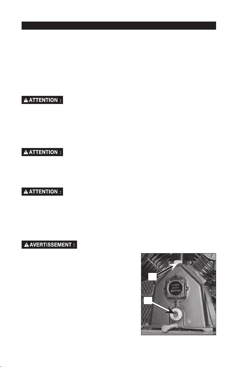
2. Retirez le bouchon de remplissage d'huile (A)
et ajoutez lentement de l'huile pour
compresseurs jusqu'à ce que le niveau atteigne
le milieu du voyant (B). REMARQUE : En
remplissant le carter, l'huile circule très
lentement dans la pompe. Si elle est versée
trop rapidement, elle débordera et le carter
semblera plein alors qu'il ne l'est pas.
REMARQUE : La capacité du carter est
d'environ 48 onces fluides (1,4 litres).
3. Remettez en place bouchon de remplissage
d'huile.
compresseur d'air lors du retrait de la palette parce que le
Les compresseurs sont expédiés avec une petite quantité
d'huile dans le carter pour les essais à l'usine. N'utilisez pas ce
Les huiles à moteur à viscosités multiples, comme l'huile 10W30, ne
devraient pas être utilisées dans un compresseur d'air. De telles huiles
N'utilisez que de l'huile conçue pour compresseurs d'air.
Purgez le réservoir pour libérer la pression d'air avant de retirer le
bouchon de remplissage d'huile ou le bouchon de vidange d'huile.
A
B
34-FRA18791
Page 35
INSTALLATION
MONTAGE DE L'APPAREIL
Emplacement du compresseur d'air
• Placez le compresseur d'air dans un endroit propre, sec et bien ventilé.
• Le compresseur d'air devrait être placé à au moins 30 cm (12 po) de distance d'un
mur ou d'autres obstructions qui pourraient nuire au débit d'air.
• Le compresseur d'air doit être situé aussi près de la source d'alimentation électrique
principale que possible pour éviter l'utilisation de câbles électriques trop longs.
REMARQUE : Les câbles électriques trop longs peuvent entraîner une perte de
puissance au moteur.
• Le filtre à air doit être propre et sans obstructions qui pourraient réduire le débit d'air
au compresseur d'air.
Ancrage du compresseur d'air
Un niveau de vibrations excessif peut affaiblir le réservoir
fixé de façon appropriée.
Le compresseur d'air doit être fixé avec des boulons à une surface solide et plane.
Pièces de fixation requises :
4 - Ancres pour béton (non fournis)
4 - Tire-fond de 3/8 po qui conviennent aux ancres pour béton (non fournis)
4 - Rondelles de 5/8 po (fournis)
cales (au besoin)
1. Placez le compresseur d'air sur une surface solide et plane.
2. Marquez la surface en utilisant les trous dans les pattes du compresseur comme
gabarit.
3. Percez des trous dans la surface de pose. Insérez-y les ancres pour béton.
4. Alignez les trous dans la surface avec les trous dans les pattes du compresseur
d'air.
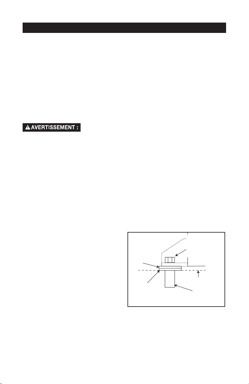
5. Placez les (4) rondelles (fournies) entre
le plancher et les pattes du
compresseur d'air. Placez, au besoin,
des cales solides entre les rondelles et
le plancher pour distribuer le poids de
façon égale sur les quatre pattes. Voir
l'illustration suivante.
6. Passez les (4) tire-fond de 3/8 po
à travers les trous des pattes du
compresseur d'air, des rondelles
et des cales et insérez-les dans les
ancres.
7. Serrez les tire-fond de 3/8 po à un
couple de 7 à 10 pi.-lbs.
d'air et causer une explosion. Le compresseur doit être
Tire-fond de
Rondelle
de 5/8 po
(fourni)
Cale sous la
rondelle (non
fourni)
3/8 po (non
fourni)
Surface de pose
Ancre pour béton
(non fourni)
35-FR A18791
Page 36

Directives de câblage
Risque de choc électrique !
inappropriée peut causer des chocs électriques. Le câblage devrait
être effectué par un électricien qualifié.
L'électricien qualifié doit savoir ce qui suit avant de commencer le câblage :
1. Si l'ampérage de la boîte de distribution électrique est suffisant. Voir le tableau des
spécifications du guide des pièces pour obtenir ces renseignements.
2. Si les câbles d'alimentation électriques ont les mêmes caractéristiques électriques
(tension, cycle, phase) que le moteur. Voir la plaque signalétique située sur la surface
latérale du moteur pour obtenir ces renseignements.
REMARQUE : Le câblage doit être de la même tension que celle indiqué sur la plaque
signalétique du moteur, plus ou moins 10%. Consultez les codes locaux pour connaître
les calibres de fils recommandés, la dimension des fils et la longueur maximum des fils.
Des fils de dimensions trop petites créent une intensité trop élevée et une surchauffe du
moteur.
Risque de choc électrique !
des surfaces chaudes, telles que le collecteur, les tubes de sortie
du compresseur, les têtes et les cylindres.
Une mise à la terre électrique
Le câblage électrique doit être éloigné
DIRECTIVES DE MISE À LA TERRE
Ce produit devrait être connecté à un système de câblage métallique permanent d'une
borne ou d'un fil conducteur de mise à la terre du produit.
Consultez les spécifications du produit au début de ce guide pour voir la tension et les
exigences minimums du circuit de dérivation.
Protection contre la surtension et protection du circuit
Consulter le tableau des spécifications pour connaître les exigences minimums
concernant la tension et le circuit de dérivation.
36-FRA18791
Page 37

Système de distribution d'air
Risque d'éclatement.
ne sont pas conçus pour l'utilisation avec un compresseur
d'air. Quoi que soit la pression nominale indiquée, les tuyaux en plastique peuvent
éclater sous la pression de l'air. N'utilisez que des tuyaux en métal pour les conduites de
distribution d'air.
L'illustration ci-dessous représente un système de distribution d'air typique. Voici
des conseils à considérer lorsque vous montez le système de distribution d'air du
compresseur d'air.
• Utilisez des tuyaux qui sont de la même dimension que l'orifice de sortie du réservoir
d'air. Des tuyaux trop petits réduisent le débit d'air.
• Si les tuyaux sont d'une longueur supérieure à 30,5 m (100 pieds), utilisez la
dimension plus large suivante.
• Enterrez les conduites en dessous de la limite de gel et évitez des pochettes où
l'eau de condensation peut s'accumuler et geler. Appliquez la pression avant de
couvrir les conduites afin de s'assurer qu'il n'y a pas de fuites aux connexions des
tuyaux.
• Nous recommandons l'installation d'un raccord flexible entre la sortie de décharge
d'air et la conduite principale d'air pour accommoder toute vibration.
• Nous recommandons l'utilisation d'un régulateur supplémentaire pour contrôler
la pression d'air. La pression d'air du réservoir est normalement trop élevée pour
alimenter des outils pneumatiques particuliers.
LES CONDUITES D'ALIMENTATION
S'INCLINENT AVEC
DÉBIT D'AIR
LE DÉBIT D'AIR
Les tuyaux en plastique ou en CPV
DÉBIT D'AIR
LES CONDUITES PRINCIPALES DE
DISTRIBUTION D'AIR
Inclinez le tuyau dans le sens du débit d'air.
L'eau de condensation s'écoule le long de
la surface inférieure des tuyaux vers les
tuyaux de vidange, empêchant ainsi l'entrée
d'eau dans les conduites d'alimentation.
RÉGULATEUR
GRAISSEUR
COLLECTEUR
DE VIDANGE
SÉPARATEUR ET
COLLECTEUR
D'HUMIDITÉ
TUYAU DE
SALETÉS
CONDUITES
D'UTILISATION
D'AIR
TUYAU DE
SALETÉS
SYSTÈME DE DISTRIBUTION
D'AIR TYPIQUE
37-FR A18791
RÉGULATEUR
ROBINET DE
RACCORDS
FLEXIBLES
SOUPAPE
À BILLE
VIDANGE
TUYAUX
VIDANGE
COLLECTEURS
DE VIDANGE
FILTRE
COMPRESSEUR
D'AIR
DE
GRAISSEUR
Page 38
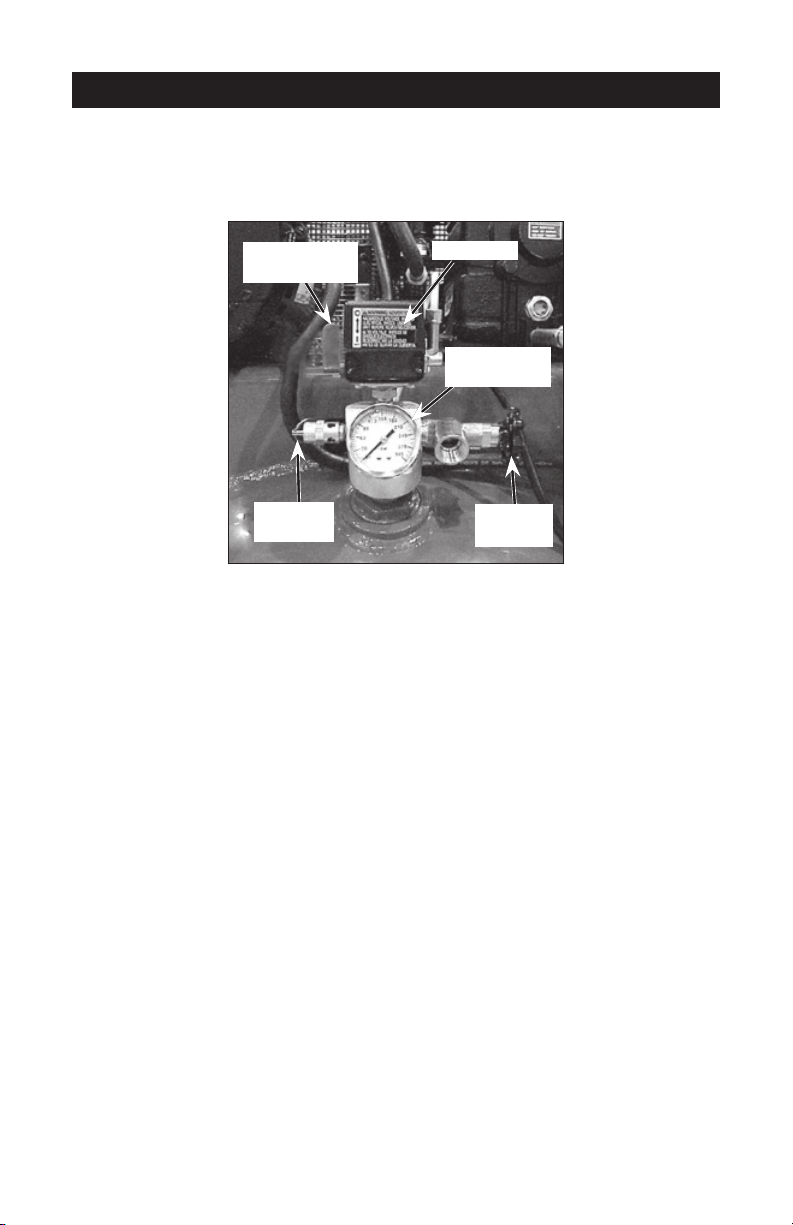
UTILISATION
Familiarisez-vous avec votre compresseur d'air
LISEZ CE GUIDE DE L'UTILISATEUR ET TOUTES LES MESURES DE SÉCURITÉ AVANT
D'UTILISER CET APPAREIL. Comparez les illustrations à votre appareil pour vous
familiariser avec l'emplacement des commandes et boutons de réglage. Conservez ce
guide pour références ultérieures.
Interrupteur
«On/Auto/Off»
Soupape
de sûreté
Description du fonctionnement
Familiarisez-vous avec ces commandes avant d'utiliser l'appareil.
Interrupteur marche/automatique/arrêt «On/Auto/Off»: Placez cet interrupteur à
la position «On/Auto» pour alimenter le manostat et à la position «Off» pour couper le
courant après chaque utilisation.
Manostat : Le manostat démarre automatiquement le moteur lorsque la pression dans le
réservoir d'air tombe à une valeur inférieure à la «pression d'amorçage» réglée à l'usine. Il
arrête le moteur lorsque la pression dans le réservoir d'air atteint la «pression de rupture»
réglée à l'usine.
Soupape de sûreté : Si le manostat n'arrête pas le compresseur d'air lorsque la
«pression de rupture» est atteinte, la soupape de sûreté protège contre toute surpression
en «sautant» à la valeur de pression établie à l'usine (une pression légèrement supérieure
à la «pression de rupture» établie pour le manostat.
Manomètre du réservoir : Le manomètre du réservoir indique la pression d'air en réserve
dans le réservoir.
Soupape à bille (à acheter séparément): Ouvre et ferme la soupape de décharge d'air.
Tournez le bouton dans le sens des aiguilles d'une montre pour fermer et dans le sens
contraire pour ouvrir.
Régulateur (vendu séparément, pas illustré) : Pour la plupart des applications, nous
recommandons l'utilisation d'un régulateur de pression d'air ou d'un épurateur d'air
séparé qui relie les fonctions de réglage de l'air et(ou) d'enlèvement de l'humidité et des
saletés.
Système de refroidissement (non illustré) : Le compresseur d'air est doté d'un système
de refroidissement d'avant garde. Le cœur de ce système est un ventilateur à technologie
avancée. Il est tout à fait normal que ce ventilateur souffle de l'air au-dessus de la
tête de la pompe, le manchon du cylindre et le carter. Vous savez que le système de
refroidissement fonctionne bien lorsque de l'air est expulsé.
Pompe du compresseur d'air (non illustrée) :
La pompe comprime l'air pour le forcer dans le réservoir d'air. L'air n'est pas disponible
pour travailler avant que le compresseur n'ait élevé la pression du réservoir d'air au
niveau requis à la sortie d'air.
Manostat
Manomètre
du réservoir
Soupape
à bille
38-FRA18791
Page 39
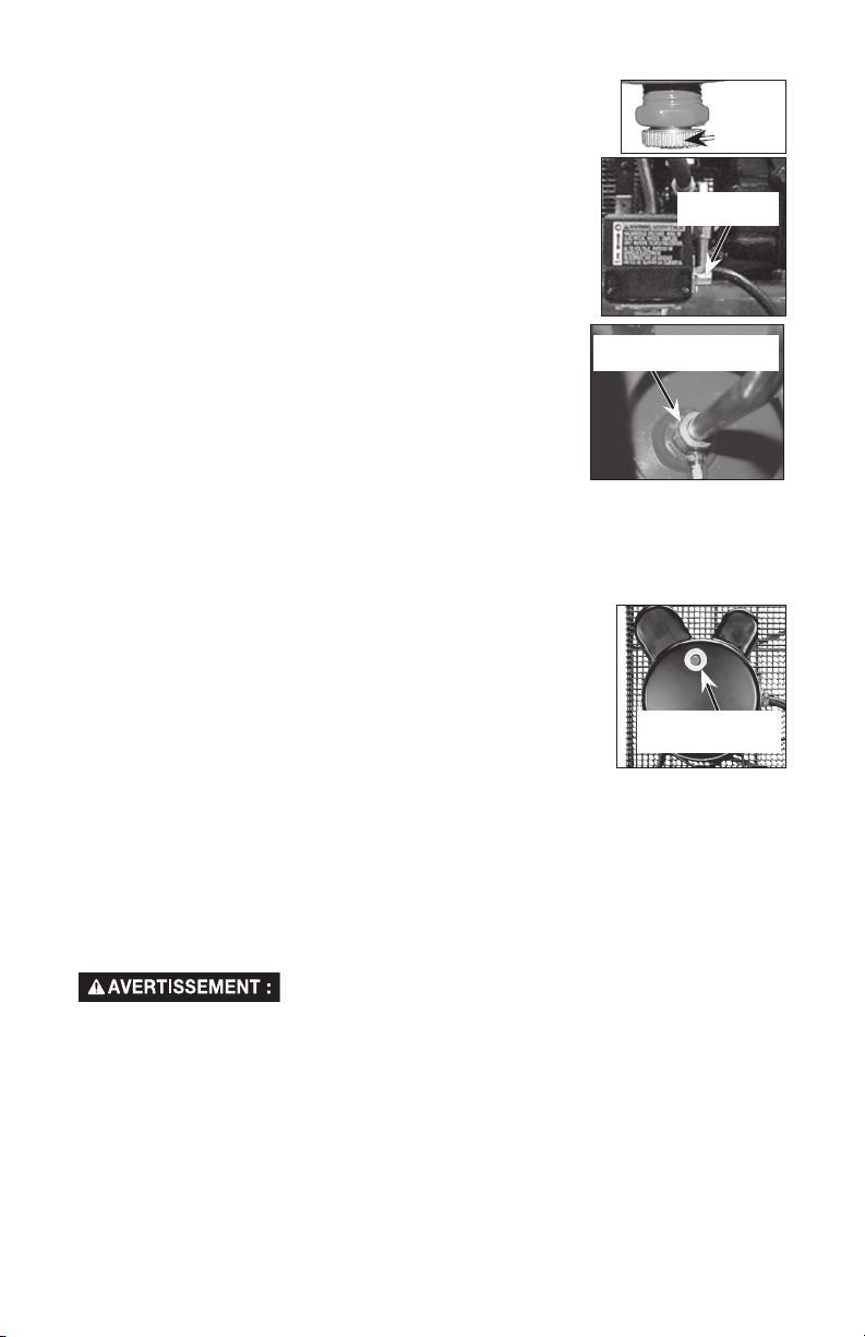
Robinet de vidange : Le robinet de vidange est situé à la base
du réservoir d'air et est utilisé pour vidanger la condensation après
chaque utilisation.
Soupape de retenue : Lorsque le compresseur fonctionne, la
soupape de retenue est «ouverte», permettant à l'air comprimé
d'entrer dans le réservoir d'air. Quand le compresseur d'air
atteint la «pression de rupture», la soupape de retenue «se
ferme», permettant à l'air pressurisé de demeurer à l'intérieur du
réservoir d'air.
Soupape de décharge de pression : La soupape de décharge
de pression, située sur le côté du manostat, est conçue pour
libérer automatiquement l'air comprimé de la tête du
compresseur et du tube de sortie lorsque le compresseur d'air
atteint la «pression de rupture» ou lorsqu'il est arrêté. La
soupape de décharge de pression permet au moteur de
redémarrer librement. Lorsque le moteur s'arrête, vous pouvez
toujours entendre l'air sortir de cette soupape pendant quelques
secondes. Vous ne devriez pas entendre une fuite d'air lorsque
le moteur est en marche ni une fois que l'appareil a atteint la
«pression de rupture».
Limiteur de surcharge du moteur : Ce moteur est doté d¹un
protecteur de surcharge thermique. Si le moteur surchauffe pour une raison quelconque,
le protecteur de surcharge arrête le moteur. Il faut laisser refroidir le moteur avant de le
redémarrer.
Pour redémarrer :
1. Placez le levier On/Auto/Off en position d¹arrêt «Off».
2. Laissez le moteur refroidir.
3. Appuyez sur le bouton rouge de rétablissement situé sur le
moteur. Placez le levier On/Auto/Off en position de marche/
automatique «On/Auto» pour redémarrer le moteur.
Filtre d'admission d'air (non illustré) : Ce filtre a été conçu
pour nettoyer l'air admis dans la pompe. Ce filtre doit être propre
en tout temps et les ouvertures d'aération doivent être sans
obstruction. Voir la section sur l'entretien.
Soupape de décharge
de pression
Bouton rouge de
rétablissement
Robinet
de
vidange
Soupape de
retenue
Utilisation de l'appareil
Arrêt de l'appareil :
1. Réglez le levier marche/ automatique/ arrêt «On/Auto/Off» à la position d'arrêt «Off».
Avant le démarrage
Procédures de rodage
Risque d'une utilisation dangereuse. Le compresseur d'air
rodage ne sont pas suivies à la lettre.
Cette procédure doit être exécutée avant d'utiliser le compresseur d'air pour la première
fois et après le remplacement de la soupape de retenue ou de la pompe complète du
compresseur.
1. Assurez-vous que le levier marche/automatique/arrêt «On/Auto/Off» est en position
d'arrêt «Off».
2. Vérifiez le niveau d'huile dans la pompe. Pour les instructions, consultez les
paragraphes « Huile » dans la section intitulée « Entretien ».
3. Vérifiez tout le câblage. Assurez-vous que les fils sont bien fixés à toutes les
connexions à bornes. Assurez-vous que tous les contacts se déplacent librement et
qu'ils ne sont pas obstrués.
peut subir d'importants dom-mages si les procédures de
39-FR A18791
Page 40

4. Ouvrez complètement la soupape à bille afin de permettre à l'air de sortir et pour
empêcher une accumulation de pression dans le réservoir d'air lors de la période de
rodage.
5. Placez le levier «On/Auto/Off» à la position «On/Auto». Le compresseur se mettra en
marche.
6. Faire fonctionner le compresseur pendant 20 minutes. Assurez-vous que la soupape
à bille est ouverte et que la pression accumulée dans le réservoir est minimale.
7. Assurez-vous qu'il n'y a pas de fuites d'air aux raccords des conduites d'air ni
aux connexions/tuyaux en y appliquant une solution savonneuse. Corrigez tout
problème, s'il y a lieu.
REMARQUE: Des fuites mineures peuvent forcer le compresseur d'air à travailler trop
fort, entraînant ainsi une panne prématurée ou un rendement médiocre.
8. Vérifiez s'il y a des vibrations excessives. Réglez la
hauteur des pieds du compresseur ou ajoutez-y des cales au besoin.
9. Après 20 minutes, fermez la soupape à bille. Le réservoir d'air se remplira jusqu'à ce
que la «pression de rupture» soit atteinte et le moteur s'arrêtera ensuite.
Avant chaque mise en marche :
1. Placez le levier «On/Auto/Off» à la position «Off».
2. Fermez la soupape à bille.
3. Raccordez le boyau et les accessoires. REMARQUE: Il faut installer un régulateur
lorsque vous utilisez des accessoires ayant une pression nominale inférieure à
175 lb/po2.
REMARQUE : Le boyau ou l'accessoire doit être muni d'une fiche à connexion rapide si
la sortie d'air est équipée d'une douille à connexion rapide.
Risque d'éclatement. Une pression d'air trop élevée
pression nominale maximum du fabricant pour tous les outils pneumatiques et
accessoires utilisés. La pression de sortie du régulateur ne doit jamais excéder la
pression nominale maximum.
conduit à un risque dangereux d'éclatement. Vérifiez la
Mise en marche :
1. Placez le levier «On/Auto/Off» à la position «On/Auto» et attendez jusqu'à ce que la
pression augmente. Le moteur s'arrêtera lorsque la pression dans le réservoir atteint
la «pression de rupture».
2. Lorsque la pression dans le réservoir atteint la «pression de rupture», ouvrez la
soupape à bille.
IMPORTANT : Lorsque vous utilisez un régulateur ou tout autre accessoire, consultez
toujours les directives du abriquant.
Le compresseur d'air est maintenant prêt pour l'utilisation.
40-FRA18791
Page 41
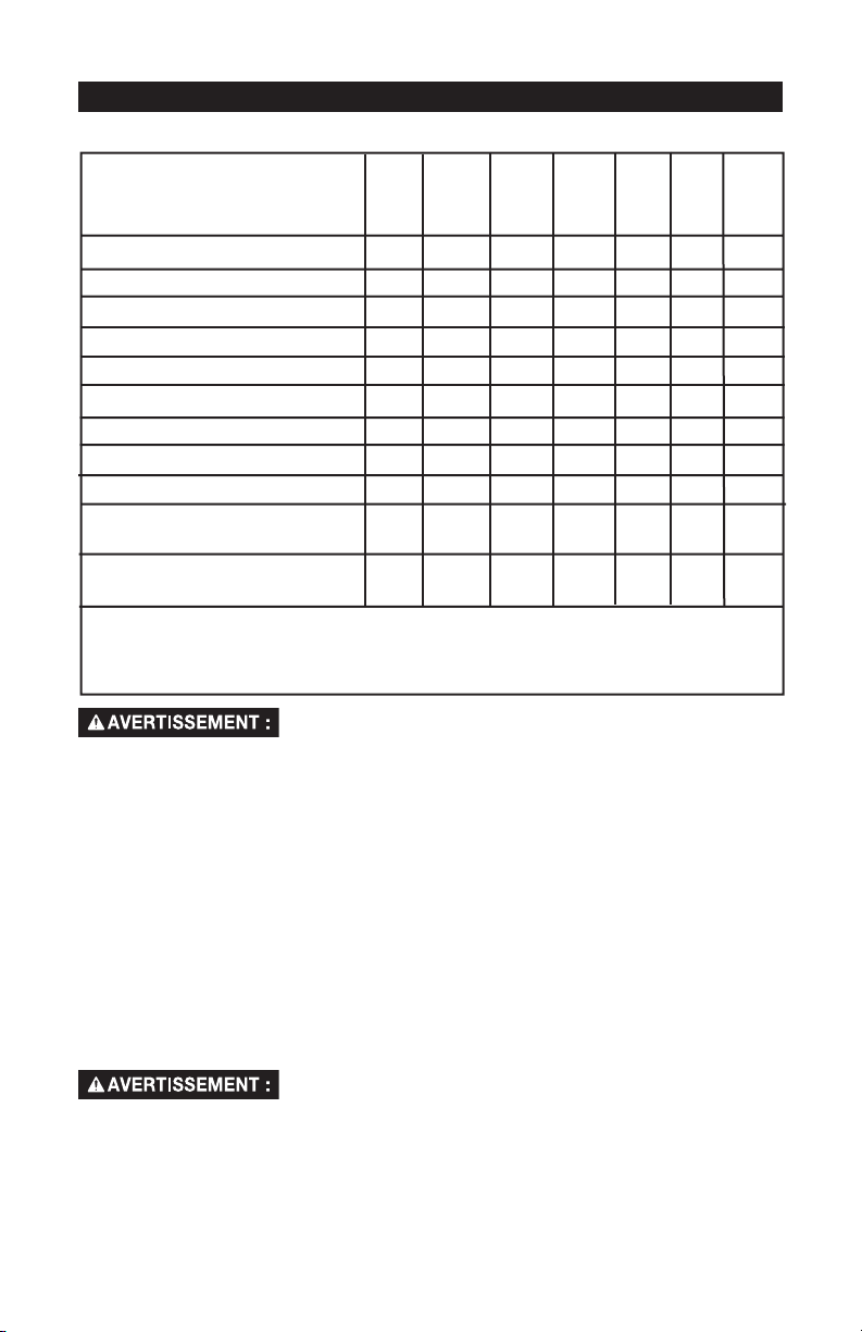
ENTRETIEN
Responsabilités du consommateur
À chaque
tranche
de 40
heures
1
●
●
À
chaque
tranche
de 100
heures
●
À
chaque
tranche
de 160
heures
●
À
chaque
année
●
À
chaque
tranche
de 8
heures
●
●
●
Vérification de la soupape de sûreté
Vidange du réservoir
Fuites d'huile
Vérification de l'huile
Avant
chaque
utilisation
●
À chaque
jour ou
après
chaque
utilisation
Changement de l'huile
Bruits ou vibrations inhabituels
●
Filtre à air
Condition de la courroie d'entraînement
Alignement de la poulie motorisée/du volant
Soupapes d'admission et de débit de la
pompe du compresseur d'air
Inspecter les conduites d'air et les
raccords pour des fuites
●
Boulons de la tête-Vérifiez la tension des boulons après les cinq premières heures de
mise en marche.
1 - plus fréquemment dans des conditions poussiéreuses ou humides
Risque d'une utilisation dangereuse. L'unité est
automatiquement en cycle quand le courant est présent.
Durant le service, vous pourriez être exposé à des sources de tension, à l'air
comprimé ou à des pièces mobiles. Avant de faire le service de l'unité, débranchez
ou déconnectez l'alimentation électrique au compresseur d'air, purgez la pression
du réservoir et laissez le compresseur d'air se refroidir.
Afin d'assurer un rendement efficace et une durée de vie utile plus longue
du compresseur d'air, un calendrier d'entretien doit être préparé et observé. Le calendrier
d'entretien ci-dessus a été établi pour un appareil utilisé tous les jours dans les conditions
normales d'un milieu de travail. Le calendrier devrait être modifié, au besoin, pour
s'adapter aux conditions d'utilisation du compresseur d'air. Ces modifications dépendent
du nombre d'heures d'utilisation et du milieu de travail. Les compresseurs d'air utilisés
dans un milieu extrêmement malpropre ou dans des conditions dures exigent des
vérifications d'entretien plus fréquentes.
REMARQUE : Consultez la section Utilisation pour connaître l'emplacement des
commandes.
Vérification de la soupape de sûreté
Risque d'éclatement.
pas correctement, une surpression pourrait avoir lieu et causer
une rupture ou une explosion du réservoir à air.
1. Avant de mettre en marche le compresseur, tirez sur l'anneau de la soupape de
sûreté pour vous assurer que la soupape fonctionne librement. Si la soupape est
coincée ou qu'elle ne bouge pas librement, elle doit être remplacée par une autre
soupape du même type.
Si la soupape de sûreté ne fonctionne
41-FR A18791
Page 42

Vidange du réservoir
REMARQUE : Operation of the air compressor will cause condensation to build up in the
air tank. Always drain tank on a washable surface or in a suitable container to prevent
damaging or staining surfaces.
1. Mettez la manette On/Auto/Off en position d'arrêt « Off ».
2.
Fermez la soupape à bille.
3. Retirez l'outil à air ou l'accessoire.
4.
Ouvrez complètement la soupape à bille afin de permettre à l'air de sortir et pour
empêcher une accumulation de pression dans le réservoir d'air lors de la période de
rodage.
5.
Fermez la soupape à bille.
6. Vidangez l'eau qui se trouve dans le réservoir à air en ouvrant le robinet
de vidange dans le fond du réservoir.
Risque d'éclatement.
d'eau apparaîtra dans le réservoir à air. Si
celui-ci n'est pas vidangé, l'eau pourrait se corroder et affaiblir le réservoir,
causant ainsi un risque de rupture du réservoir.
7. Une fois l'eau vidangée, refermez le robinet de vidange.
Le compresseur peut maintenant être entreposé.
REMARQUE : Si le robinet de vidange à l'égout est obstrue, laissez
s'échapper complètement la pression d'air. Le robinet de vidange
pourra alors être retirée, nettoyée et remise en place.
Une condensation
Huile
REMARQUE : Utilisez une huile conçue spécifiquement pour les
compresseurs d'air, telle que l'huile pour compresseurs d'air PAS1 de Porter-Cable.
L'huile peut être acheté au magasin où vous avez acheté le compresseur d'air.
REMARQUE : La capacité du carter est d'environ 48 onces fluides (1,4 litres).
Vérification
1. Le niveau d'huile devrait se situer au milieu du voyant.
2. Retirez le bouchon de remplissage d'huile (A) et, si nécessaire, ajoutez lentement de
l'huile jusqu'à ce que le niveau se situe au milieu du voyant.
Changement
1. Retirez le culot du trou de remplissage
d'huile (A).
2. Retirez le culot de vidange de l'huile (B)
et vidangez l'huile dans un contenant
approprié.
3. Remettez en place le culot de vidange
d'huile (B) et resserrez-le.
4. Ajoutez lentement de l'huile pour
compresseurs jusqu'à ce que le
niveau se situe au milieu du voyant
(C). REMARQUE : En remplissant le
carter, l'huile circule très lentement
dans la pompe. Si elle est versée trop
rapidement, elle semblera déborder et
le carter semblera plein alors qu'il ne
l'est pas.
Risque d'une utilisation dangereuse.
causera un malfonctionnement prématuré du compresseur. Évitez de
trop remplir.
5. Remettez en place le culot du trou de remplissage (A) et resserrez-le.
A
C
Le fait de trop remplir d'huile
Soupape de
vidange ouverte
Soupape de
vidange fermée
B
42-FRA18791
Page 43

Filtre à air - Inspection et remplacement
Surfaces chaudes. Risque de brûlures. Les têtes du
retiré. Avant de commencer, laissez refroidir le compresseur.
Un filtre à air encrassé ne permettra pas au compresseur de fonctionner à sa pleine capacité.
Assurez-vous que le filtre à air est propre en tout temps.
1. Retirez le filtre à air.
2. Retirez
3. Retirez
IMPORTANT: N'utilisez pas le compresseur une fois le filtre retiré.
4. Placez le nouveau filtre à air dans le couvercle. Pour obtenir le numéro de pièce requis,
5.
le
couvercle du filtre à air.
le
filtre à air du couvercle.
consultez le guide des pièces de rechange.
Remettez en place le couvercle de filtre à air et remontez le filtre à la pompe.
compresseur sont exposées lorsque le couvercle du filtre est
Gardez le filtre à air propre à tout temps. N'utilisez pas le
compresseur d'air lorsque le filtre à air est retiré.
Courroie – Remplacement
(Consultez le Livret des pièces pour connaître le numéro de pièce de la
courroie de rechange)
Risque de graves blessures ou de dommages par exposition
pièces mobiles. Ne jamais faire fonctionner l’appareil sans le carter de courroie. Le carter de
courroie ne devrait être enlevè que lorsque le compresseur de air est dèbranchè.
1. Éteignez et verrouillez le compresseur d'air puis libérez toute pression d’air dans le
réservoir d'air.
2. Retirez le garde-courroie.
3. Marquez la position de la pompe sur la selle.
4. Desserrez les vis de fixation du moteur et glissez le moteur vers le compresseur d'air.
5. Enlevez la courroie et remplacez-la par une courroie neuve.
6. Voir « Réglage de la tension de la courroie » avant de serrer les pièces de fixation du
moteur.
Réglage de tension de la courroie
1. Glissez le moteur à la position originale et alignez-le avec la marque que vous avez
faite auparavant sur la selle.
2. Serrez les deux vis de fixation externes du moteur juste assez pour maintenir le moteur
en place et pour permettre la vérification de l'alignement de la poulie et du volant.
3. La courroie devrait avoir une déflexion de 3/16 po (4,8 mm) au milieu, entre la poulie
et le volant, quand un poids de 5 à 10 lb (2,3 à 4,5 kg) est appliqué au point de michemin.
4. Fois que la bonne tension de
courroie est obtenue, serrez les quatre
vis de fixation du moteur. Consultez le
guide des pièces pour connaître les
spécifications sur le couple de
serrage.
REMARQUE : Une fois que la poulie du
moteur a été déplacée de sa position
d'origine réglée à l'usine, les rainures
du volant et de la poulie doivent être
alignées jusqu'à 1/16 po (1,6 mm)
pour éviter une usure excessive de
la courroie. Vérifiez l'alignement en
exécutant la procédure suivant d'alignement de la poulie et du volant-moteur.
de vêtements amples, parties du corps ou autres articles aux
Force descendante
Déflexion
43-FR A18791
Page 44

Alignement de la poulie et du volant-moteur
REMARQUE : Une fois que la poulie du moteur a été déplacée de sa position d'origine
réglée à l'usine, les rainures du volant et de la poulie doivent être alignées jusqu'à 1/16 po
(1,6 mm) pour éviter une usure excessive de la courroie.
Le volant et la poulie du compresseur d'air doivent être alignés (sur un même plan) jusqu'à
1/16 po (1,6 mm) pour assurer que la courroie repose bien dans les rainures du volant.
Pour vérifier l'alignement, suivez les étapes suivantes :
1. Arrêtez le compresseur d'air, verrouillez la source d'alimentation et libérez tout l'air
pressurisé du réservoir d'air.
2. Retirez le garde-courroie.
3. Placez une règle sur l'extérieur du volant et de la poulie du moteur.
4. Mesurez la distance entre le rebord de
la courroie et la règle aux points A1 et
A2 de l'illustration. La différence entre
les mesures ne doit pas dépasser 1/16
po (1,6 mm).
5. Si la différence est supérieure à 1/16
po (1,6 mm), desserrez la vis de fixation
fixant la poulie du moteur à l'arbre et
réglez la position de la poulie sur l'arbre jusqu'à ce que les mesures A1 et A2 ne soient
plus qu'à 1/16 po (1,6 mm) l'une de l'autre.
6. Resserrez la vis de fixation de la poulie du moteur. Consultez le guide des pièces pour
connaître les spécifications sur le couple de serrage.
7. Effectuez une inspection visuelle de la poulie du moteur pour vous assurer qu'elle est
bien perpendiculaire à l'arbre moteur. Les points B1 et B2 de l'illustration devraient
sembler égaux. S'ils ne le sont pas, desserrez la vis de fixation de la poulie du moteur
et égalisez les points B1 et B2 en vous assurant de ne pas nuire à l'alignement de la
courroie que vous avez effectué à l'étape 2.
8. Resserrez la vis de fixation de la poulie du moteur. Consultez le guide des pièces pour
connaître les spécifications sur le couple de serrage.
9. Remettez en place le garde-courroie.
Soupapes d'admission et d’échappement de la pompe du
compresseur d'air
Une fois par année, faites appel à un technicien qualifié pour vérifier les soupapes
d'admission et d’échappement de la pompe du compresseur d'air.
Inspection des conduites d'air et des raccords pour des fuites
1. Mettez le compresseur d'air en marche afin de déterminer s'il y a des fuites d'air.
2. Appliquez une solution savonneuse à tous les raccords, connexions et tuyaux des
conduites d'air.
3. Éliminez toutes les fuites trouvées.
IMPORTANT : Même des fuites mineures peuvent forcer le compresseur d'air à travailler
trop fort, entraînant ainsi une panne prématurée ou un rendement médiocre.
Boulons de la tête du compresseur - serrage
Les boulons de la tête du compresseur doivent être maintenus à un couple de serrage
approprié. Vérifiez le couple de serrage des boulons après les cinq premières heures
d'utilisation. Resserrez au besoin. Consultez le guide des pièces pour connaître les
spécifications sur le couple de serrage.
44-FRA18791
Page 45

ENTRETIEN ET RÉGLAGES
TOUS LES SERVICES D'ENTRETIEN NE FIGURANT PAS ICI DOIVENT ÊTRE EXÉCUTÉS
PAR UN TECHNICIEN QUALIFIÉ.
Risque d'une utilisation dangereuse. L'unité est automa-
le service, vous pourriez être exposé à des sources de tension, à l'air comprimé ou à
des pièces mobiles. Avant de faire le service de l'unité, débranchez ou déconnectez
l'alimentation électrique au compresseur d'air, purgez la pression du réservoir et
laissez le compresseur d'air se refroidir.
1. Laissez s'échapper toute la pression du réservoir. Voir " Vidange du réservoir » dans la
section « Entretien ».
2.
Éteignez et verrouillez le compresseur d'air puis libérez toute pression d’air dans le
réservoir d'air.
3. Avec une clé réglable, relâchez l'écrou du tube de débit, au réservoir d'air et à la pompe.
Soigneusement, éloignez le tube de débit du clapet.
4. Avec une clé réglable, relâchez l'écrou du tube de détente, au réservoir d'air et au pressostat.
Soigneusement, éloignez le tube de détente du clapet.
5. Dévissez le clapet (en le faisant tourner dans le sens contraire des aiguilles d'une montre)
à l'aide d'une clé plate de 22 mm (7/8 po.) Remarquez l'orientation du clapet pour le
réassemblage.
6. À l'aide d'un tournevis, poussez avec soin
le disque de soupape vers le haut et le bas.
REMARQUE : Le disque de soupape devrait
pouvoir bouger librement vers le haut et le
bas sur le ressort qui le retient en position
fermée. Si ce n'est pas le cas, la soupape
doit être nettoyée ou remplacée.
7. Nettoyez ou remplacez le clapet. Un
solvant, comme du diluant à peinture ou du
décapant pour vernis, peut être utilisé pour
nettoyer le clapet.
8. Appliquez le solvant sur les filets du clapet.
Réinstallez le clapet (faites tourner dans le sens des aiguilles d'une montre).
9. Replacez le tube de détente. Resserrez les écrous.
10. Replacez le tube de débit et resserrez les écrous.
11. Entreprenez le processus d'amorçage. Voir « Processus d'amorçage » dans la section
Opération.
tiquement en cycle quand le courant est présent. Durant
Remplacement ou nettoyage de la soupape
Tournevis
En position
ouverte,
rien n'est
visible.
En position fermée,
le disque est visible.
Service d’entretien additionnel
Le démontage ou un entretien du compresseur d’air au-delà de ce qui est indiqué dans ce guide
ne sont pas recommandés. Si un entretien plus poussé est requis, communiquez avec le Centre de
service sous garantie autorisé le plus proche.
45-FR A18791
Page 46

RANGEMENT
Avant de ranger le compresseur d'air, effectuez les étapes suivantes :
1. Revoyez la section intitulée «Entretien» des pages précédentes et exécutez
l'entretien requis.
2. Placez le levier «On/Auto/Off» à la position «Off».
3. Fermez la soupape à bille.
4. Débranchez l'outil pneumatique ou l'accessoire.
5. Ouvrez la soupape à bille et permettez à l'air de purger lentement du réservoir
jusqu'à ce que la pression du réservoir soit d'environ 20 lb/po2.
6. Vidangez l'eau du réservoir d'air en ouvrant le robinet de vidange situé en bas du
réservoir.
L'eau dans le réservoir d'air peut condenser. Si le réservoir
du réservoir d'air, causant ainsi un risque d'éclatement du réservoir.
7. Une fois la vidange de l'eau terminée, fermez le robinet de vidange.
REMARQUE : Si le robinet de vidange est engorgé, libérez tout l'air pressurisé. Le
robinet de vidange peut alors être enlevé, nettoyé et réinstallé.
8. Protégez le cordon électrique et le boyau d'air contre tout dommage (de façon à ce
qu'ils ne soient pas coincés ou écrasés).
Rangez le compresseur d'air dans un endroit propre et sec.
n'est pas vidangé, l'eau corrodera et affaiblira les parois
46-FRA18791
Page 47

DÉPANNAGE
Risque d'une utilisation dangereuse. L'unité est automa-
le service, vous pourriez être exposé à des sources de tension, à l'air comprimé ou
à des pièces mobiles. Avant de faire le service de l'unité, débranchez ou déconnectez l'alimentation électrique au compresseur d'air, purgez la pression du réservoir et laissez le compresseur d'air se refroidir.
tiquement en cycle quand le courant est présent. Durant
PROBLÈME
Pression excessive
dans le réservoir
- la soupape de
sûreté saute.
Fuite d'air aux
raccords.
Fuite d'air à la
soupape de
retenue ou à
l'intérieur de
celle-ci.
Fuite d'air à la
soupape de
décharge du
manostat
Fuite d'air du
réservoir ou aux
soudures du
réservoir
CAUSE
Le manostat ne met pas le
moteur hors tension lorsque le
compresseur atteint la « pression
de rupture ».
La pression de rupture du manostat est trop élevée.
Les raccords des tubes ne sont
pas assez serrés.
Le siège de la soupape de
retenue est endommagé.
Soupape de décharge du manostat défectueuse.
Réservoir d'air défectueux. Le réservoir doit être remplacé.
CORRECTION
Mettez la manette On/Auto/Off à
la position d'arrêt « Off ».
Si l'appareil ne s'arrête pas,
adressez-vous à un technicien
qualifié.
Adressez-vous à un technicien
qualifié.
Resserrez les raccords où vous
entendez l'air s'échapper. Vérifiez
les raccords à l'aide d'une solution
d'eau savonneuse. ÉVITEZ DE
TROP SERRER.
Une soupape de retenue
défectueuse produit une fuite
d'air constante au niveau de la
soupape de décharge de pression
lorsqu'il existe une pression dans
le réservoir et que le compresseur
est hors tension. Remplacez la
soupape de retenue. Voir
« Remplacement ou nettoyage
de la soupape de retenue » de la
section Utilisation.
Adressez-vous à un technicien
qualifié.
Ne réparez pas la fuite.
Risque d'éclatement. Évitez de
percer, de souder ou de modifier le réservoir d'air de quelque
façon. Celui-ci risquerait de
rompre ou d'exploser.
Fuite d'air entre la
tête et la plaque
de la soupape.
Fuite au joint. Adressez-vous à un technicien
qualifié.
47-FR A18791
Page 48
PROBLÈME
Le relevé de pression indiqué sur le
manomètre réglé
(si fourni) chute
lorsqu'un accessoire est utilisé.
Fuite d'air au
niveau de la soupape de sûreté.
CAUSE
Il est normal qu'une
certaine chute de pression
ait lieu.
Défectuosité possible de la
soupape de sûreté.
CORRECTION
S'il y a une chute excessive de
pression lorsqu'un accessoire est
utilisé, ajustez le régulateur en suivant les instructions de la section
« Utilisation ».
REMARQUE : Réglez la pression
régularisée dans des conditions de
débit (pendant que l'accessoire est
utilisé).
Actionnez la soupape de sûreté manuellement en tirant sur l'anneau. Si la
soupape fuit toujours, remplacez-la.
Le compresseur
n'émet pas assez
d'air pour faire
fonctionner les
accessoires.
Usage d'air prolongé ou excessif.
Le compresseur n'est pas assez puissant pour les exigences
en air.
Trou dans le boyau.
Soupape de retenue obstruée.
Fuites d'air.
Filtre d'admission d'air obstrué.
Courroie desserrée.
Réduisez l'usage d'air.
Vérifiez l'exigence en air des accessoires. Si elle est supérieure à la valeur
en pi3/min ou à la pression fournie par
votre compresseur d'air, vous avez besoin d'un compresseur plus puissant.
Vérifiez et remplacez-le au besoin.
Retirez et nettoyez la soupape ou
remplacez-la.
Resserrez les raccords.
Nettoyez ou remplacez le filtre
d'admission d'air. N'utilisez pas le
compresseur d'air une fois le filtre
enlevé. Voir le paragraphe « Filtre
d'air » de la section Entretien.
Vérifiez la tension de la courroie.
Voir « Réglage de tension de la
courroie » de la section Entretien.
48-FRA18791
Page 49
PROBLÈME
Le moteur ne
tourne pas.
CAUSE
Le protecteur contre la surcharge
du moteur a été déclenché.
La pression du réservoir excède
la « pression d'amorçage » du
manostat.
Soupape de retenue coincée en
position ouverte.
Vérifiez les connexions des fils
dans le manostat et dans la boîte
de raccordement.
Possibilité de défectuosité du
moteur ou du condensateur de
démarrage.
Peinture vaporisée sur les pièces
internes du moteur.
La soupape de décharge de pression du manostat n'a pas dégagé
la pression des têtes.
Fusible sauté, disjoncteur
déclenché.
CORRECTION
Laissez le moteur refroidir et le protecteur de surcharge se réinitialisera
automatiquement.
Le moteur démarrera automatiquement une fois que la pression du
réservoir tombe à un niveau inférieur
à la « pression d'amorçage » du
manostat.
Retirez et nettoyez la soupape ou
remplacez-la.
Vérifiez les connexions des fils dans
le manostat et dans la boîte de raccordement.
Adressez-vous à un technicien qualifié.
Adressez-vous à un technicien qualifié.
N'utilisez pas le compresseur d'air dans
l'aire de vaporisation de peinture. Voir
l'avertissement au sujet des vapeurs
inflammables.
Purgez la ligne en mettant le levier du
manostat en position d'arrêt « Off ». Si la
soupape ne s'ouvre pas, remplacez-la.
1. Vérifiez la boîte à fusibles pour y
trouver le fusible sauté et, le cas
échéant, remplacez-le. Réinitialisez le disjoncteur. N'utilisez pas
de fusible ou de disjoncteur dont
la puissance nominale excède
celle précisée pour ce circuit de
dérivation particulier.
2. Vérifiez si le fusible est du type
approprié. Vous devriez utiliser un
fusible temporisé.
3. Assurez-vous qu'il n'y a aucune
situation de basse tension et assurez-vous d'utiliser une rallonge
appropriée.
4. Débranchez tout autre appareil
électrique du circuit ou utilisez
le compresseur sur son propre
circuit de dérivation.
La soupape
de sûreté de
la pompe se
déclenche.
Il se peut que le manostat,
la soupape de sûreté ou la
pompe doive être réparé.
49-FR A18791
Adressez-vous à un technicien
qualifié.
Page 50

PROBLÈME
Bruit de cliquetis
CAUSE
Problème possible de la soupape
de sûreté.
CORRECTION
Opérez la soupape de sûreté manuellement en tirant sur l'anneau.
soupape fuit toujours, remplacez-la.
Si la
Usure excessive
de la courroie.
Soupape de retenue défectueuse.
Poulie desserrée.
Volant-moteur desserré.
Vis de montage du compresseur
desserrées.
Courroie desserrée.
Accumulation de carbone dans
la pompe.
Courroie trop serrée.
Courroie desserrée.
Retirez et nettoyez la soupape ou
remplacez-la.
Resserrez la vis de fixation de la
poulie. Consultez le guide des pièces
pour connaître le couple de serrage
spécifié.
Resserrez la vis du volant-moteur.
Consultez le guide des pièces pour
connaître le couple de serrage
spécifié.
Resserrez les vis de montage du
compresseur. Consultez le guide des
pièces pour connaître le couple de
serrage spécifié.
Vérifiez la tension de la courroie. Voir
« Réglage de tension de la courroie » de la section Entretien.
Adressez-vous à un technicien
qualifié.
Vérifiez la tension de la courroie. Voir
« Réglage de tension de la courroie » de la section Entretien.
Vérifiez la tension de la courroie. Voir
« Réglage de tension de la courroie »
de la section Entretien.
Sifflement.
Courroie trop serrée.
Poulie desserrée.
Poulie mal alignée.
La pompe du compresseur
manque d'huile.
Courroie desserrée.
50-FRA18791
Vérifiez la tension de la courroie. Voir
« Réglage de tension de la courroie »
de la section Entretien.
Adressez-vous à un technicien
qualifié.
Voir le paragraphe « Alignement de
la poulie et du volant-moteur » de la
section Entretien.
Voir le paragraphe sur la vérification
de l'huile de la section Entretien.
Vérifiez la tension de la courroie. Voir
« Réglage de tension de la courroie »
de la section Entretien.
Page 51

NOTES
51-FR A18791
Page 52

GARANTIE LIMITÉE
DeVilbiss Air Power Company garantit à l'acheteur original, qui utilise le produit comme bien de
consommation (utilisé à des fins personnelles, résidentielles ou domestiques) que tous les produits couverts
par cette garantie sont exempts de défauts de matériaux et de fabrication pour une période d'un an à
partir de la date d'achat. Tous les produits couverts par cette garantie limitée qui sont utilisés à des fins
commerciales (c.-à-d. produisant un revenu) sont exempts de défauts de matériaux et de fabrication pour
une période de 90 jours à partir de la date d'achat. Les produits couverts par cette garantie comprennent
les compresseurs d'air, les outils pneumatiques, les pièces de rechange, les laveuses à pression et les
génératrices.
DeVilbiss Air Power Company réparera ou remplacera, à sa discrétion, les produits ou composants s'étant
avérés défectueux dans les limites de la période de garantie. Les services seront effectués en respectant
l'ordre normal des travaux, lors d'une journée ouvrable, aux installations du Centre de service après-vente
et selon la disponibilité des pièces de rechange nécessaires. Toute décision prise par DeVilbiss Air Power
Company en ce qui concerne cette garantie limitée est finale.
Cette garantie vous donne certains droits particuliers. Il se peut que vous ayez d'autres droits, variant d'une
province à l'autre et d'un état à l'autre.
RESPONSABILITÉ DE L'ACHETEUR D'ORIGINE (utilisateur initial) :
• Pour faire une réclamation de garantie pour ce produit, NE retournez PAS le produit au détaillant. Le
produit doit être évalué par le personnel d'un Centre de service après-vente agréé. Pour connaître
l'emplacement du Centre de service après-vente agréé le plus près de chez vous, composez le
1-800-888-2468, 24 heures par jour, 7 jours par semaine ou visitez notre site Web à www.devap.com.
• Conservez le reçu de caisse original comme preuve d'achat pour toute réparation sous garantie.
• Appliquez tous soins raisonnables lors de l'utilisation et de l'entretien du produit, conformément aux
recommandations dans le ou les guide(s) de l'utilisateur.
• Livrez ou expédiez le produit au Centre de service après-vente agréé le plus proche. Le fret doit, le cas
échéant, être acquitté par l'acheteur.
• Les compresseurs d'air à réservoir de 60 et 80 gallons (227 et 303 litres) seront inspectés sur les lieux
de leur installation. Veuillez communiquer avec le Centre de service après-vente agréé le plus proche
offrant le service sur place, pour faire les arrangements nécessaires dans un tel cas.
• Tout acheteur qui n'est pas satisfait de l'intervention du Centre de service après-vente agréé est prié de
communiquer directement avec DeVilbiss Air Power Company.
CETTE GARANTIE NE COUVRE PAS CE QUI SUIT :
• Marchandise remise à neuf, utilisée comme équipement de location ou modèles de salon ou
d'exposition.
• Marchandise ayant cessé de fonctionner en raison d'usure normale, d'usage abusif*, d'exposition
au froid, à la chaleur, à la pluie, à l'humidité excessive ou au gel, d'usage de produits chimiques non
appropriés, de négligence, d'accidents, de tout manquement à observer les directives d'utilisation
du produit figurant dans le ou les guide(s) de l'utilisateur fournis avec le produit, d'un entretien non
approprié, de l'utilisation d'accessoires ou de pièces non recommandées par DeVilbiss Air Power
Company, ou de réparations ou de modifications non approuvées.
* Un compresseur d'air pompant de l'air plus longtemps que le cycle de service recommandé durant
une période d'une heure peut être considéré comme ayant subi un usage abusif.
• Frais de réparation et de transport de marchandise non reconnue comme étant défectueuse.
• Coûts associés à l'assemblage, l'ajout nécessaire d'huile, les réglages ou autres frais d'installation et de
mise en marche.
• Pièces ou accessoires consommables, fournis avec le produit, et qui deviennent inutilisables ou
inopérants après une période raisonnable d'utilisation, y compris, mais sans être limités aux disques
ou tampons de ponçage, lames de scie et de ciseaux, pierres meulières, ressorts, burins, buses, joints
toriques, gicleurs d'air, rondelles et accessoires similaires.
• Marchandise vendue par DeVilbiss Air Power Company mais fabriquée par et identifiée comme étant le
produit d'une autre compagnie,tels que les moteurs à essence. Dans ce cas, la garantie du fabricant du
produit s'applique, si une telle garantie est offerte.
• TOUTE PERTE, TOUT DOMMAGE DIRECT OU INDIRECT OU TOUT FRAIS POUVANT RÉSULTER
D'UN DÉFAUT QUELCONQUE, D'UNE DÉFAILLANCE OU D'UN MAUVAIS FONCTIONNEMENT
DU PRODUIT. Certaines provinces et certains états ne permettent pas l'exclusion ni la limitation
des dommages directs ou indirects. Par conséquent, il se peut que les exclusions ou limitations
mentionnées ci-dessus ne s'appliquent pas dans votre cas.
• TOUTES GARANTIES IMPLICITES, Y COMPRIS CELLES PORTANT SUR LA VALEUR
MARCHANDE ET L'APPLICATION DU PRODUIT POUR UNE UTILISATION PARTICULIÈRE, SONT
LIMITÉES À UN AN À COMPTER DE LA DATE D'ACHAT D'ORIGINE. Certaines provinces et certains
états ne permettent pas la limitation de la période d'une garantie implicite. Par conséquent, il se peut
que les limitations mentionnées ci-dessus ne s'appliquent pas dans votre cas.
213 Industrial Drive • Jackson, TN 38301-9615
Téléphone : 1-800-888-2468
Télécopieur : 1-800-888-9036
52-FRA18791
Page 53
CUADRO DE ESPECIFICACIONES
Normas de seguridad/definiciones. . . . . . . .53
Información de seguridad para el
consumidor . . . . . . . . . . . . . . . . . . . . . . . . . .53
Instrucciones importantes de seguridad. . . . . .
. . . . . . . . . . . . . . . . . . . . . . . . . . . . . . . . . . 53-58
Especificaciones . . . . . . . . . . . . . . . . . . . . . .59
Glosario . . . . . . . . . . . . . . . . . . . . . . . . . . . . . .59
Ciclo de Servicio . . . . . . . . . . . . . . . . . . . . . .59
Accesorios . . . . . . . . . . . . . . . . . . . . . . . . . . .59
Ensamblado . . . . . . . . . . . . . . . . . . . . . . . . . .60
Operación . . . . . . . . . . . . . . . . . . . . . . . . . 64-66
Mantenimiento . . . . . . . . . . . . . . . . . . . . . 67-70
Servicio y Ajustes . . . . . . . . . . . . . . . . . . . . . .71
Almacenaje . . . . . . . . . . . . . . . . . . . . . . . . . . .72
Guía de diagnóstico de problemas. . . . .73-76
Notes . . . . . . . . . . . . . . . . . . . . . . . . . . . . . . . .77
Garantía . . . . . . . . . . . . . . . . . . . . . . . . . . . . .78
English . . . . . . . . . . . . . . . . . . . . . . . . . . . . 1-26
Français . . . . . . . . . . . . . . . . . . . . . . . . . .27-52
Instalación . . . . . . . . . . . . . . . . . . . . . . . . . 61-63
DEFINICIONES DE NORMAS DE SEGURIDAD
Este manual contiene información que es importante que usted conozca y comprenda. Esta información se relaciona con la protección de SU SEGURIDAD y LA PREVENCIÓN DE PROB-
LEMAS A SU EQUIPO. Para ayudarlo a reconocer esta información, usamos los símbolos
indicados más abajo. Sírvase leer el manual y prestar atención a estas secciones.
Indica una situación
de riesgo inminente,
que si no se evita, causará la muerte o
lesiones serias.
Indica una situación poten-
cialmente riesgosa, que si no se evita,
podría causar la muerte o lesiones
serias.
peligrosa, que si no se evita, puede
causar lesiones menores o moderadas.
alerta indica una situación potencialmente
riesgosa la que, si no se evita, podría
causar daños en la propiedad.
Indica una situación
potencialmente
Usado sin el símbolo
de seguridad de
INSTRUCCIONES IMPORTANTES DE SEGURIDAD
Algunos tipos de polvo creados por herramientas motorizadas de lijado, aserra-
tienen materiales químicos conocidos (en el Estado de California) como causantes de cáncer, defectos de
nacimiento u otras lesiones del aparato reproductivo. Algunos ejemplos de estos productos químicos son:
• El plomo contenido en algunas pinturas con base de plomo.
• Sílice cristalizado proveniente de los ladrillos, el cemento y otros productos de albañilería.
• Arsénico y cromo provenientes del tratamiento químico dado a la madera.
Su riesgo a esas exposiciones variará dependiendo de la frecuencia con la que usted realice
diferentes tipos de trabajo. Para reducir su exposición a la acción de dichos agentes químicos:
Trabaje en zonas bien ventiladas y hágalo con equipo de seguridad aprobado,
facial o respirador aprobado por MSHA / NIOSH cuando opere esas herramientas.
Al utilizar herramientas neumáticas también deben tomarse precauciones básicas de seguridad, a fin
de reducir la posibilidad de riesgo de lesiones personales.
do, amolado/esmerilado, perforado u otras actividades de la construcción, con-
use siempre protección
53-SP A18791
Page 54
INSTRUCCIONES IMPORTANTES DE SEGURIDAD
GUARDE ESTAS INSTRUCCIONES
La operación o el mantenimiento inadecuados de este producto podrían ocasionar
lesiones serias y daños a la propiedad. Lea y comprenda todas las advertencias e
instrucciones de funcionamiento antes de utilizar este equipo.
PELIGRO
ADVERTENCIA: Riesgo de Explosión o Incendio
¿Qué puede occurrir?
Es normal que los contactos eléctricos del
motor y del interruptor de presión emitan
chispas.
Si las chispas eléctricas provenientes del
compresor tomaran contacto con
emanaciones de materiales inflamables,
ellos podrían arder originando incendio o
explosión.
Restringir cualquiera de las aberturas de
ventilación causará un serio recalentamiento
y podría producir un incendio.
Dejar desatenida esta unidad mientras está
en funcionamiento puede causar lesiones
personales o daños a la propiedad. Para
reducir el riesgo de incendio, no permita que
el compresor opere desatendido.
¿Cómo prevenirlo?
Siempre opere el compresor en un sector
bien ventilado y sin materiales combustibles,
gasolina o emanaciones de solventes.
En un área de rociado de materiales inflamables,
ubique el compresor por lo menos a 6,1m (20
pies) de distancia del área de rociado. Podría
requerirse una extensión de la manguera.
Almacene los materiales inflamables en una
ubicación segura, alejados del compresor.
Jamás coloque objetos apoyados o sobre el
compresor. Opere el compresor en un sector
abierto, alejado por lo menos 30 cm (12") de
cualquier pared u obstrucción que restrinja el
flujo de aire fresco a las aberturas de ventilación.
Opere el compresor en un sector limpio, seco, y
bien ventilado. No opere la unidad en espacios
cerrados o cualquier área confinada.
Manténgase siempre alerta cada vez que el
producto este funcionando.
Siempre desconecte el suministro eléctrico
moviendo la palanca conmutadora de presión a la posición de apagado (off y drene el
tanque diariamente o después de cada uso.
54-SPA18791
Page 55
PELIGRO
ADVERTENCIA: Riesgo de Explosión
Tanque de aire: las siguientes condiciones podrían, causar el debilitamiento del tanque, y
causar su explosión violenta, daños a la propiedad o lesiones serias.
¿Qué puede occurrir?
El drenaje inadecuado del agua condensada
en el tanque le causa óxido que reduce el
espesor del tanque de acero.
Modificaciones o intento de reparaciones al
tanque.
Modificaciones no autorizadas a la válvula
de descarga, válvula de seguridad o cualquier
otro componente que controle la
presión del tanque.
La vibración excesiva puede debilitar
el tanque de aire y causar su ruptura o
explosión.
ADITAMENTOS Y ACCESORIOS
Exceder la presión especificada para las
herramientas neumáticas, pistolas rociadoras,
accesorios activados por aire, llantas neumáticas
y otros objetos inflables, puede causar su
explosión o que salgan disparados, pudiendo
ocasionar lesiones serias.
PELIGRO
¿Cómo prevenirlo?
Drene el tanque diariamente o después de
cada uso. Si el tanque genera una pérdida,
reemplácelo inmediatamente con un nuevo
tanque o reemplace el compresor completo.
Jamás perfore, suelde, o efectúe modificación
alguna al tanque o sus accesorios.
El tanque está diseñado para resistir presiones
operativas específicas. Jamás efectúe ajustes o
sustituya partes que alteren las regulaciones
de presión originales de fábrica.
Para un control preciso de la presión, debe usted
instalar un regulador y un medidor de presión
a la salida del aire de su compresor (Si no
estuviese equipado) Siga las recomendaciones de
los fabricantes de su equipo y jamás exceda los
valores máximos de presión permitidos para los
accesorios. Jamás use el compresor para inflar
objetos que requieren poca o baja presión,
tales como juguetes para los niños, pelotas de
fútbol, pelotas de básquet, etc.
ADVERTENCIA: Riesgo de Objetos Arrojados por el Aire
¿Qué puede occurrir?
El chorro de aire comprimido puede causar
lesiones a los tejidos blandos de la piel
expuesta y puede propulsar suciedad, astillas,
partículas
velocidad, ocasionando
lesiones personales.
sueltas y pequeños objetos a alta
daños a la propiedad o
Al utilizar el compresor, use siempre
anteojos de seguridad con protección lateral
aprobados según la norma Z87.1 de ANSI.
Jamás apunte boquilla o pulverizador alguno
hacia partes del cuerpo, a otras personas o
animales.
Siempre apague el compresor y purgue la
presión de la manguera de aire y del tanque,
antes de intentar el mantenimiento, el acople de
herramientas o accesorios.
55-SP A18791
¿Cómo prevenirlo?
Page 56
PELIGRO
ADVERTENCIA: Riesgo de Descarga Eléctrica
¿Qué puede occurrir?
Su compresor de aire está accionado por
electricidad. Como cualquier otro dispositivo
eléctrico accionado eléctricamente, si no se lo
utiliza adecuadamente, podría causarle una
descarga eléctrica.
Las reparaciones intentadas por personal no
calificado podrían ocasionar lesiones serias o
la muerte por electrocución.
CONEXIÓN A TIERRA: Dejar de proveer una
conexión adecuada a tierra a esta unidad
podría ocasionar lesiones serias o la muerte
por electrocución. Vea las instrucciones para la
puesta a tierra.
PELIGRO
ADVERTENCIA: Riesgo de Inhalación
¿Qué puede occurrir?
El aire comprimido proveniente del compresor
no es sano para respirar. El chorro de aire
puede contener monóxido de carbono o
partículas sólidas del tanque. La inhalación
de esos contaminantes puede llegar a causar
lesiones serias o la muerte.
¿Cómo prevenirlo?
Jamás opere el compresor a la intemperie
cuando está lloviendo o en condiciones de
humedad. Nunca opere el compresor sin sus
cubiertas o si estuviesen dañadas.
Cualquier conexión eléctrica o reparación
requerida por esta unidad debe hacerla el
personal de los servicentros autorizados de
acuerdo a los códigos eléctricos nacionales y
locales.
Asegúrese que el circuito eléctrico al cual está
conectado el compresor, tiene conexión apro-
piada a tierra, el voltaje correcto y protección
adecuada por fusibles.
¿Cómo prevenirlo?
El aire del compresor jamás debe usarse
directamente para consumo humano; a menos
que primero se le instale filtros adecuados y
un equipo de seguridad en línea, capaces de
procesar el aire de acuerdo a todos los códigos
locales y federales.
El rociado de materiales tales como pintura,
solventes, removedores de pintura, insecticidas,
herbicidas, produce emanaciones nocivas y
venenosas.
Trabaje en un área con buena ventilación
cruzada. Lea y siga las instrucciones de
seguridad provistas en el rótulo o en los datos
de las hojas de seguridad del material que está
pulverizando. Use el respirador aprobado por
NIOSH/MSHA designado para utilizarse con su
aplicación específica.
56-SPA18791
Page 57
PELIGRO
ADVERTENCIA: Riesgo de Quemaduras
¿Qué puede occurrir?
Tocar el metal expuesto tal como el cabezal
del compresor o los tubos de salida del escape,
puede ocasionarle quemaduras serias.
PELIGRO
ADVERTENCIA: Riesgo de Partes Móviles
¿Qué puede occurrir?
Partes movibles tales como la polea, el volante
y la correa podrían ser la causa de lesiones
serias usted ci o su ropa entran en contacto con
ellas.
Intentar operar el compresor con piezas
dañadas o faltantes, o repararlo sin sus
cubiertas puestas, puede exponerlo a usted
a piezas en movimiento que le ocacionen
lesiones serias.
¿Cómo prevenirlo?
Jamás toque partes de metal expuestas en el
compresor durante o inmediatamente después
de la operación. El compresor permanecerá
caliente por varios minutos luego de la
operación.
No burle las cubiertas protectoras o intente el
mantenimiento hasta que la unidad se enfríe.
¿Cómo prevenirlo?
Nunca opere el compresor sin sus cubiertas o
si estuviesen dañadas.
Cualquier reparación requerida por esta unidad
debe hacerla el personal de un servicentro
autorizado.
ADVERTENCIA: Riesgo de Caída
¿Qué puede occurrir?
Un compresor portátil puede caerse de la
mesa, el banco de trabajo o del techo pudiendo
dañarse y causar lesiones serias o la muerte
del operador.
PELIGRO
¿Cómo prevenirlo?
Siempre opere el compresor en una posición
estable y segura a fin de prevenir el movimiento
accidental de la unidad. Jamás opere el
compresor sobre un techo u otra posición
elevada. Utilice mangueras adicionales de
aire para alcanzar posiciones altas.
57-SP A18791
Page 58

PELIGRO
ADVERTENCIA: Riesgo de Lesiones Serias o Daños a la Propiedad al
Transportar el Compresor
(Fuego, inhalación, daño a la superficie de vehículos)
¿Qué puede occurrir?
El aceite puede derramarse generando un ries-
go de incendio o inhalación que puede causar
lesiones serias o muerte. El derrame de aceite
daña alfombras, pinturas u otras superficies de
vehículos o remolques.
Deposite el compresor sobre una alfombrilla
protectora cuando lo transporte a fin de
proteger el contra los goteos. Retire el compresor del vehículo inmediatamente después de
su arribo al destino.
¿Cómo prevenirlo?
PELIGRO
ADVERTENCIA: Riesgo de Operación Insegura
¿Qué puede occurrir?
La operacion insegura de su compresor de aire
podría ocasionarle lesiones serias o la muerte
a usted u otros.
CONSERVAR ESTAS INSTRUCCIONES
¿Cómo prevenirlo?
Revise y comprenda todas las instrucciones y
advertencias contenidas en este manual.
Familiarícese con los métodos de operación y
control del compresor de aire.
Mantenga libre la zona de operaciones de
personas, animales domésticos y obstáculos.
Mantenga alejados a los niños del compresor
de aire en todo momento.
No opere el producto cuando se encuentre
fatigado o bajo la influencia de alcohol o
drogas. Esté alerta en todo momento.
Jamás altere los elementos de seguridad de
este producto.
Equipe la zona de operaciones con un
extinguidor de fuego.
No opere la máquina si ésta tiene partes
faltantes, rotas o no autorizadas.
58-SPA18791
Page 59

ESPECIFICACIONES
Modelo N° E7540
Potencia de trabajo 6,0
Voltaje / Fases 240V/1 Fase
Requerimientos mínimos por ramal de circuito 30 Amp
Tipo de fusible Fusible de retardo
Capacidad del tanque en galones 80 ASME, Vertical (302,8 litros)
Presión aproximada de conexión 140 PSIG
Presión aproximada de desconexión 175 PSIG
SCFM @ 100 PSIG 14,0
SCFM @ 175 PSIG 13,5
GLOSARIO
Familiarícese con los siguientes términos, antes de operar la unidad:
CFM: (Cubic feet per minute) Pies cúbicos por minuto.
SCFM: (Stardard cubic feet per minute) Pies cúbicos estándar por minuto; una unidad de
medida que permite medir la cantidad de entrega de aire.
PSIG: (Pound per square inch) Libras por pulgada cuadrada.
Código de certificación: Los productos que usan una o más de las siguientes marcas:
UL, CUL, ETL, CETL, han sido evaluados por OSHA, laboratorios independientes certificados en seguridad, y reúnen los estándares suscriptos por los laboratorios dedicados a
la certificación de la seguridad.
Presión Aprox. de Conexión: Cuando el motor está apagado, la presión del tanque
de aire baja a medida que usted continúa usando su accesorio. Cuando la presión
del tanque baja al valor fijado en fábrica como punto bajo, el motor volverá a arrancar
automáticamente. La presión baja a la cual el motor arranca automáticamente, se llama
presión "mínima de corte".
presión aprox. de desconexión: Cuando un compresor de aire se enciende y comienza
a funcionar, la presión de aire en el tanque comienza a aumentar. Aumenta hasta un valor
de presión alto fijado en fábrica antes de que el motor automáticamente se apague protegiendo a su tanque de aire de presiones más altas que su capacidad. La presión alta a
la cual el motor se apaga se llama presión "máxima de corte".
Ramal: Circuito eléctrico que transporta electricidad desde el panel de control hasta el
tomacorriente.
Para bloquear el acceso a la corriente: Coloque un candado en el interruptor de circuito para que nadie pueda activar la corriente.
CICLO DE SERVICIO
Esta bomba compresora de aire es capaz de funcionar continuamente, sin embargo para
prolongar la vida útil de su compresor de aire se recomienda mantener un ciclo promedio
de servicio que oscile entre el 50% y el 75%; ello significa que la bomba compresora no
debería trabajar más de 30 a 45 minutos por hora.
ACCESORIOS
Los accesorios pueden encontrarse en el comercio donde fue comprada la unidad, o en
un local de artículos de ferretería.
59-SP A18791
Page 60

ENSAMBLADO
Contenido de la Caja
1 - Compresor de aire 1 - Manual del operador
1 - Bolsa de piezas conteniendo lo siguiente: 4 - Arandelas de 16 mm (5/8 pulg.)
1 - Manual de piezas
Herramientas necesarias para el ensamble
1 - llave de tubo o de boca de 14 mm (9/16 pulg.)
1 - Taladro eléctrico
Desembalaje
1. Extraiga todo el embalaje
Podrá ser necesario apuntalar o soportar un lado del equipo al
inclinarse.
2. Extraiga y descarte los (4) tornillos y arandelas que sujetan el compresor a la
plataforma.
3. Con la ayuda de otra persona, remueva cuidadosamente el compresor de aire de su
plataforma y colóquelo sobre una plataforma nivelada.
Para agregar aceite a la bomba
sin antes agregarle la cantidad adecuada de aceite al cárter de la bomba, porque
puede dañarse seriamente aún con un mínimo de operación sin la cantidad
adecuada. Asegúrese de completar el procedimiento de asentamiento antes de
operar el compresor.
carbono en componentes críticos, reduciendo el rendimiento y la vida útil del
compresor. Use solamente aceite para compresor de aire.
NOTA: Se incluye el aceite en algunas unidades. Si el aceite no estuviese incluido, utilice
un tipo de aceite específicamente formulado para ser utilizado en compresores de aire,
tales como el aceite Porter-Cable PAS1 para compresores de aire. Dicho tipo de aceite
puede hallarse en los comercios en los que se vende el compresor de aire.
1. Coloque la unidad en sobre superficie nivelada.
drenaje del aceite.
2. Extraiga el tapón del aceite (A) y lentamente
agregue aceite al compresor, hasta alcanzar la
mitad de la línea indicadora del visor de
vidrio (B). NOTA: Si se le agrega aceite muy
rápido, el cárter se rebalsará y aparentará estar
lleno. Llene lentamente el cárter hasta el tope
del orificio de llenado. NOTA: La capacidad del
cárter es aproximadamente de 1,4 litros
(48 onzas fluidas).
3. Colocar la tapa de llenado de aceite.
extraer la plataforma, porque el compresor de aire tenderá a
Los compresores se despachan con algo de aceite debido a la
prueba en fábrica, pero no suficiente. No opere este compresor
No se deben usar aceites de viscosidad múltiple como 10W30
en compresor alguno de aire. Estos aceites dejan depósitos de
Drene el tanque a fin de liberar la presión de aire antes de
extraer la tapa para el relleno de aceite, o el tapón para
A
B
60-SPA18791
Page 61

INSTALACIÓN
CÓMO PREPARAR LA UNIDAD
Ubicación del compresor de aire
• Instale el compresor de aire en una zona limpia, seca y bien ventilada.
• Instale el compresor de aire a una distancia no menor de 30 cm (12 pulg.) de la pared u
otras obstrucciones que pudiesen interferir con el flujo del aire.
• Instale el compresor de aire lo más cerca posible del sitio de alimentación eléctrica,
a fin de evitar el uso de largas extensiones de cableado eléctrico. NOTA: Las
extensiones eléctricas demasiado largas pueden causar una caída de tensión
perjudicial para la alimentación del motor.
• El filtro de aire debe mantenerse libre de obstrucciones que pudiesen reducir el flujo
del aire al compresor.
Anclaje del compresor de aire
La vibración excesiva puede debilitar al tanque de aire y
adecuadamente.
El compresor de aire DEBE anclarse a una superficie sólida y nivelada.
Elementos necesarios:
4 - Tarugos para anclajes en cemento (no suministrados)
4 - Tornillos tirafondo de 3/8 pulg. capaces de llenar los tarugos para anclaje en
cemento (no suministrados)
4 - Arandelas 5/8 pulg. (suministrada)
- Cuñas (en caso de ser necesario)
1. Instale el compresor de aire sobre una superficie sólida y nivelada.
2. Marque la superficie utilizando como plantilla, los orificios existentes en el
compresor de aire.
3. Perfore la superficie, a fin de penetrar los tarugos para anclaje en el cemento. Coloque
los tarugos en el cemento.
4. Haga coincidir la alineación de los orificios de la superficie, con el de las patas del
compresor de aire.
5. Coloque las (4) arandelas
(suministradas) entre el piso y las patas
del compresor. Si fuese necesario,
pueden colocarse cuñas sólidas entre
las arandelas y el piso a fin de
distribuir en forma pareja el peso sobre
las cuatro patas. Vea la figura
siguiente.
6. Coloque los (4) tornillos tirafondo de
3/8 pulg. a través de las patas del
compresor de aire; de las arandelas
y cuñas, hasta llegar a los tarugos de
anclaje.
7. Aplique un torque de 7-10 pies-lbs. al
los tornillos tirafondo de 3/8 pulg.
causar su explosión. El compresor debe estar montado
Arandela de 5/8
pulg. (suministrada)
Cuña
debajo de la
arandela (no
suministrada)
Tornillo
tirafondo de
3/8 pulg. (no
suministrado)
Línea de superficie
Tarugos para anclaje
en cemento (no
suministrados)
61-SP A18791
Page 62

Instrucciones para la conexión eléctrica
Riesgo de Choque Eléctrico. Una conexión a tierra inadecuada
ser efectuadas por un electricista calificado.
Antes de efectuar las conexiones, un electricista calificado debe conocer lo siguiente:
1. Que el valor promedio del amperaje en la caja eléctrica sea el adecuado. Para
obtener dicha información deberá referirse a la hoja de especificaciones del manual
de piezas.
2. Que la línea de suministro eléctrico tenga idénticas características eléctricas
(voltaje, ciclos, fases) que las del motor. Para obtener dicha información deberá
referirse a la placa de identificación del motor, ubicada sobre el lateral del mismo.
NOTA: La conexión eléctrica debe corresponder al mismo voltaje indicado sobre la
placa de identificación del motor mas o menos 10%. Para informarse acerca de las
extensiones y calibres de cable recomendadas y máxima extensión del circuito, deberá
referirse a los códigos locales; un circuito subdimensionado origina una caída elevada
del amperaje y un recalentamiento del motor.
ubicada fuera de superficies calientes, tales como silenciadores de escape, tubos
de salida de compresores de aire, cabezales o cilindros.
puede ocasionar electrocución. Las conexiones eléctricas deben
Riesgo de Choque Eléctrico. La conexión eléctrica debe estar
INSTRUCCIONES PARA CONECTAR A TIERRA
Este artefacto debe conectarse al terminal metálico de un sistema de cableado
permanente a tierra para equipos o al terminal del artefacto.
Protección del voltaje y del circuito
Consulter le tableau des spécifications pour connaître les exigences minimums
concernant la tension et le circuit de dérivation.
62-SPA18791
Page 63

Sistema de distribución de aire
Riesgo de Explosión. Los tubos de plástico o PVC no han
Independientemente de lo que esté indicado como especificación de presión, las
cañerías de plástico pueden explotar debido a la presión del aire. Utilice solamente
caños de metal para los ramales de distribución.
La siguiente imagen representa un sistema típico de distribución de aire. Las siguientes
son pautas para tener presente al montar el sistema de distribución del compresor de
aire.
• Utilice caño de la misma medida que el de la salida del tanque de aire. Una cañería
demasiado angosta restringirá el paso del aire.
• Si la cañería tiene más de
30,5 m (100 pies) de longitud, utilice la medida inmediata superior.
• Entierre la cañería por debajo de la línea de congelamiento y evite huecos en los
que la condensación se pudiese acumular y congelar. Efectúe pruebas de presión
antes de cubrir la cañería, a fin de asegurarse que todas las uniones de la misma se
encuentran libres de fugas.
• Se recomienda la instalación de un acoplamiento flexible, entre la salida de descarga
del aire y la línea principal de distribución del mismo, a fin de aliviar eventuales
vibraciones.
• Se recomienda la instalación de un segundo regulador para el control de la presión
del aire. La presión de salida del tanque es - usualmente - demasiado alta para las
herramientas individuales de acción neumática.
FLUJO DEL
AIRE
CAÑERÍAS PRINCIPALES DE DISTRIBUCIÓN
DEL AIRE. La pendiente del caño se inclina en
dirección al sentido del flujo del aire. La
condensación del agua fluye a lo largo del
fondo del caño hacia los caños de descarga,
previniendo su entrada a los caños que
alimentan las líneas.
sido diseñados para usarlos con aire comprimido.
PENDIENTE DE LA TUBERÍA
DE ALIMENTACIÓN CON FLUJO
DE AIRE
CAÑERÍAS
PARA USO
DEL AIRE
FLUJO DEL
AIRE
CAÑ0S
DE
DRENAJE
LUBRICADOR
SEPARADOR DE
HUMEDAD Y TRAMPA
COLUMNA DE
DESECHOS
REGULADOR
TRAMPA PARA
DRENAJE
SISTEMA TÍPICO DE
DISTRIBUCIÓN DE AIRE
TRAMPA PARA
DRENAJE
COLUMNA DE
DESECHOS
FILTRO
ACOPLAMIENTO
FLEXIBLE
VÁLVULA ESFERICA
VÁLVULA-GRIFO DE PURGA
REGULADOR
COMPRESIÓN
DE AIRE
LUBRICADOR
63-SP A18791
Page 64
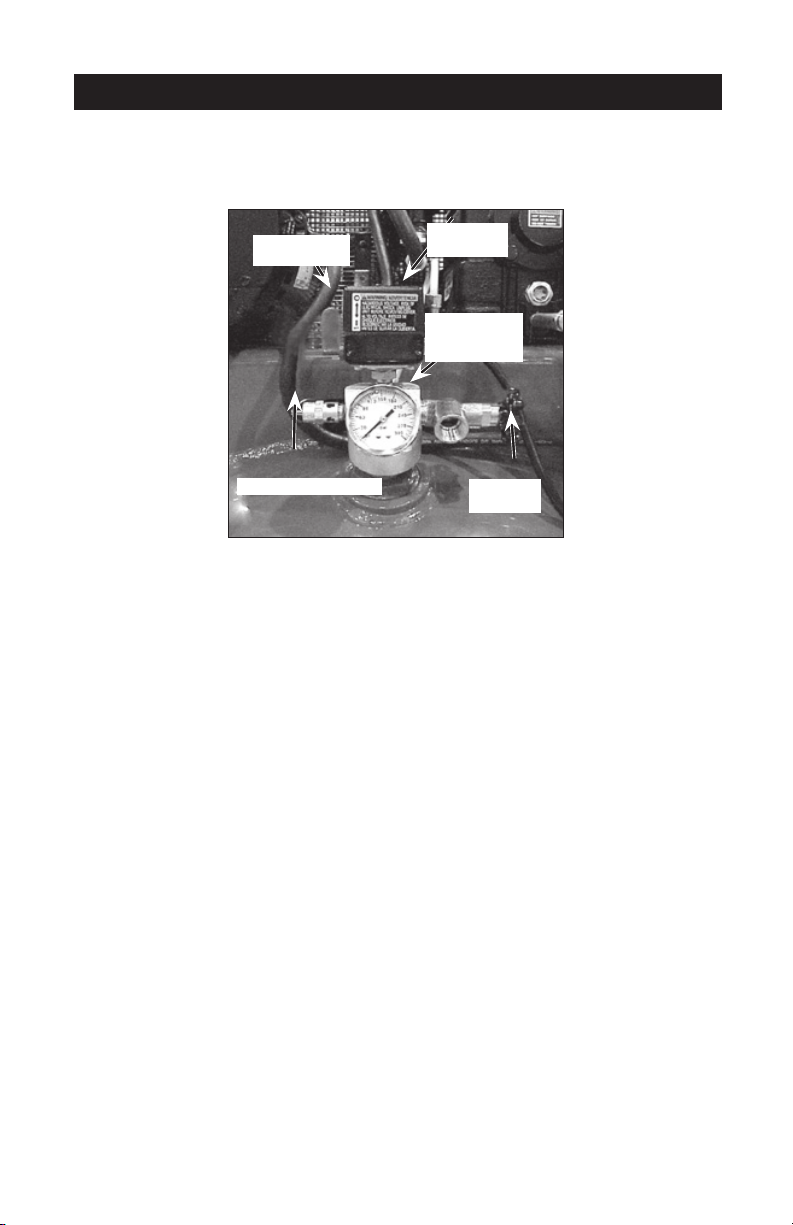
OPERACIÓN
Conozca su compresor de aire
LEA ESTE MANUAL DEL PROPIETARIO Y SUS NORMAS DE SEGURIDAD ANTES DE
OPERAR LA UNIDAD. Compare las ilustraciones contra su unidad a fin de familiarizarse
con la ubicación de los distintos controles y regulaciones. Conserve este manual para
referencias futuras.
Interruptor
On/Auto/Off
Interruptor
de presión
Manómetro
de presión
del tanque
Válvula de seguridad
Válvula de
globo
Descripción de operaciones
Familiarícese con estos controles antes de operar la unidad.
Interruptor On/Auto/Off: Mueva este interruptor a la posición "On/Auto" para dar con-
tacto automático al interruptor de presión, y "Off" para interrumpir la energía eléctrica al
término del uso.
Interruptor de presión: El interruptor de presión permite el arranque automático del motor cuando la presión del tanque disminuye por debajo del valor de la presión de conexión
regulada en fábrica. El motor se detendrá cuando la presión del tanque alcance los
valores de presión de corte, regulado en fábrica para su desconexión.
Válvula de seguridad: Si el interruptor de presión dejara de cortar el suministro de presión del compresor conforme a los valores prefijados para la presión de corte, la válvula
de seguridad protegerá contra la presión elevada, "saltando" de acuerdo a los valores
prefijados en fábrica (ligeramente superiores a los de presión de corte de la llave interruptora.)
Manómetro de la presión del tanque: El manómetro que controla la presión del tanque
indica la reserva de presión del tanque de aire.
Válvula de globo: (vendida por separado): Abre y cierra la válvula de descarga de
aire. Gire la perilla en sentido antihorario para abrir, y en sentido horario para cerrar.
Regulador (vendido por separado, no mostrado): Para la mayoría de aplicaciones se
recomienda usar un regulador de presión o un transformador de aire separado que combine las funciones de regulación de aire y/o eliminación de humedad y tierra.
Sistema de enfriamiento (no mostrado): Este compresor contiene un sistema de enfriamiento de avanzada. El núcleo de este sistema de enfriamiento contiene un ventilador
diseñado especialmente. Resulta perfectamente normal para este ventilador, soplar aire a
través del cabezal de la bomba, la camisa del pistón y el cárter del cigüeñal. Usted sabrá
que el sistema de enfriamiento funciona adecuadamente cuando perciba que el aire está
siendo expelido.
Bomba de compresión del aire (no mostrada): Comprime el aire dentro del tanque.
El aire de trabajo no se encuentra disponible hasta que el compresor haya alcanzado a
llenar el tanque hasta un nivel de presión por encima del requerido para la salida del aire.
64-SPA18791
Page 65
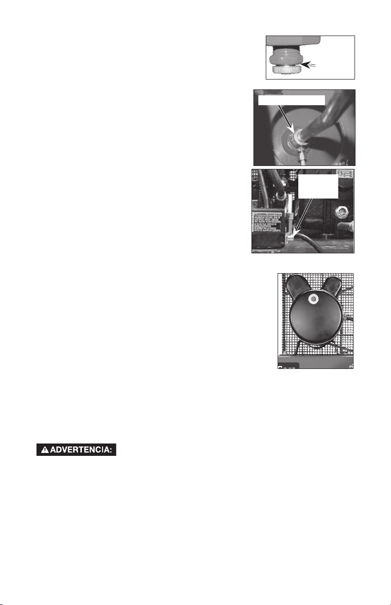
Válvula de drenaje: La válvula de drenaje se encuentra
ubicada sobre la base del tanque de aire y se usa para drenar la
condensación al fin de cada uso
Válvula reguladora: Cuando el compresor de aire se encuentra funcionando, la válvula reguladora esta "abierta", permitiendo la entrada del aire comprimido al tanque de aire. Cuando
el nivel de presión del tanque alcanza el punto de "corte",
la válvula reguladora "se cierra", reteniendo la presión del
aire dentro del tanque.
Válvula aliviadora de presión: La válvula aliviadora de
presión se encuentra ubicada en el costado del interruptor
de presión; ha sido diseñada para liberar automáticamente
el aire comprimido de la cabeza compresora y el tubo de
salida, cuando el compresor de aire alcanza la presión de
"corte" o es apagado. La válvula aliviadora de presiónpermite el arranque libre del motor. Cuando el motor se
detiene, debería escucharse el escape del aire a través de
dicha válvula durante unos segundos. No debe escucharse escape alguno mientras el motor está en
marcha, ni pérdidas continuas una vez que se alcanzó la
presión "de corte".
Protector de sobrecalentamiento del motor: Este
motor tiene un protector manual de sobrecarga térmica.
Si el motor se sobrecalienta por cualquier motivo, el
protector de sobrecarga apaga el motor. Debe permitirse
que el motor enfríe antes de volverlo a arrancar de la siguiente forma:
1. Mover la palanquita de On/Auto/Off a la posición de "Off".
2. Permitir que el motor se enfríe.
3. Presionar el botón rojo de Reinicialización (Reset) que está en
el motor.
4. Para arrancar el motor mover la palanquita de On/Auto/Off a la
posición de "On/Auto".
Filtro para la entrada del aire (no mostrado): Este filtro está
diseñado para limpiar el aire que entra a la bomba. Dicho filtro
debe estar siempre limpio y los orificios de ventilación libres de
obstrucciones. Vea "Mantenimiento".
Válvula reguladora
Válvula
de
drenaje
Válvula
aliviadora
de presión
Cómo utilizar su unidad
Cómo detenerla:
1. Coloque la posición de la llave interruptora On/Auto/Off en la posición "Off".
Antes de ponerlo en marcha
Procedimiento de asentamiento
Riesgo de Operación Insegura.
no fuesen seguidas estrictamente, podrán ocurrir serios daños.Este
procedimiento es necesario antes de poner en servicio al compresor de aire, y cuando la
válvula reguladora o la bomba completa del compresor haya sido reemplazada.
Este procedimiento es necesario antes de poner en servicio el compresor de aire y cuando la
válvula reguladora o la bomba completa del compresor hayan sido reemplazadas.
1. Asegúrese que la palanca On/Auto/Off se encuentra en la posición "Off".
2. Verifique el nivel de aceite en la bomba. Para recibir instrucciones, lea al párrafo
"Aceite" en la sección Mantenimiento.
3. Vuelva a verificar todas las conexiones. Asegúrese de que todos los cables se
encuentren firmes en todos los terminales de sus conexiones. Asegúrese de que todos
los contactos se muevan libremente, y que no existan obstrucciones.
65-SP A18791
Si las siguientes instrucciones
Page 66

4. Abra completamente la válvula de asiento, a fin de permitir el escape del aire y prevenir
la acumulación de presión de aire dentro del tanque, durante el periodo de asentamiento.
5. Mueva la palanca On/Auto/Off a la posición "On/Auto". El compresor se pondrá en
marcha.
6. Haga funcionar el compresor durante 20 minutos. Asegúrese que la válvula de asiento se
encuentre abierta y que la presión del tanque sea mínima.
7. Aplicando una solución jabonosa, verifique todas las conexiones / cañerías, a fin detectar
fugas de aire. Corrija si fuese necesario. NOTA: Pérdidas menores pueden ocasionar una
carga adicional de trabajo al compresor, dando como resultado su rotura prematura o
una performance inadecuada.
8. Verifique la existencia de vibración excesiva. Reajuste o acuñe el pie del compresor, si
ello fuese necesario.
9. Luego de 20 minutos, cierre la válvula de asiento. El aire recibido elevará la presión hasta
el punto de la "presión de corte" y ello hará detener el motor.
Antes de cada puesta en marcha:
1. Coloque el interruptor On/Auto/Off en la posición "Off" y cierre el regulador de aire.
2. Cierre la válvula de asiento.
3. Conecte la manguera y accesorios.
para menos de 175 PSI, DEBERÁ instalarse un regulador.
NOTA: Tanto la manguera como los accesorios requerirán un enchufe de conexión rápida si la
salida del aire está equipada con un zócalo de conexión rápida.
Riesgo de Explosión. Demasiada presión de aire podrá ser la causa
de riesgo de explosión. Verifique los valores de máxima presión
dados por el fabricante de las herramientas neumáticas y los accesorios. La presión de
salida del regulador jamás debe exceder los valores de máxima presión especificados.
NOTA: Cuando se instalen accesorios especificados
Cómo poner en marcha:
1. Mueva la palanca On/Auto/Off a la posición "On/Auto" y deje que se incremente la presión del
tanque. El motor se detendrá una vez alcanzado el valor de presión "de corte" del tanque.
2. Cuando la presión del tanque alcance el valor de "presión de corte", se abrirá la válvula
de asiento.
IMPORTANTE: al utilizar un regulador y otros accesorios, refiérase a las instrucciones del
fabricante.
El compresor estará listo para ser usado.
66-SPA18791
Page 67
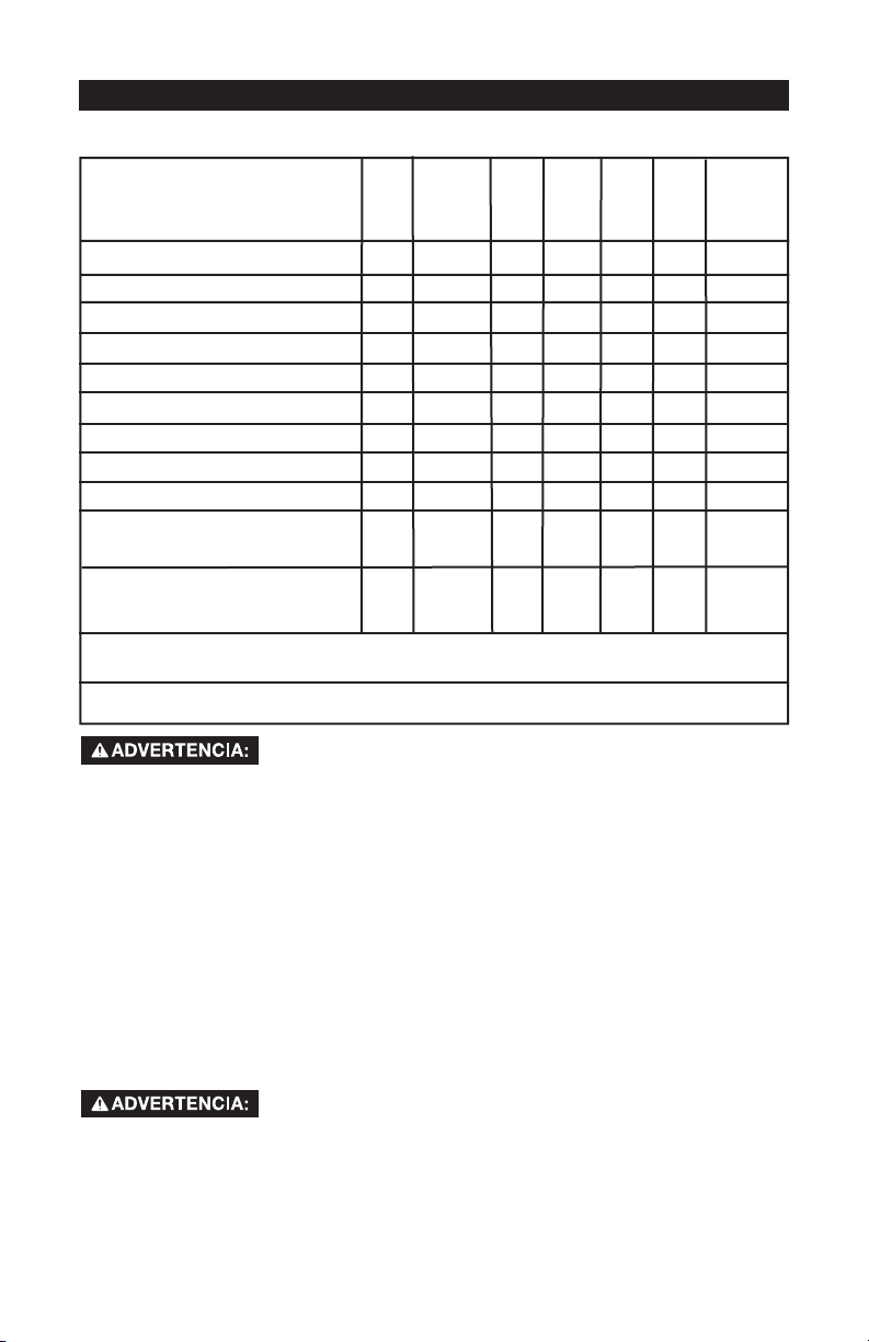
MANTENIMIENTO
Responsabilidades del cliente
Antes
Diariamente
de
o luego de
cada
cada uso
uso
Verifique la válvula de seguridad
Drenaje del tanque
Pérdidas de aceite
Verifique el aceite de la bomba
Cambie el aceite de la bomba
Ruido inusual y/o vibración
Filtro de aire
Estado de la correa
Alineado de la polea/volante del motor
Válvulas de entrada y escape de
la bomba del compresor de aire
Inspección de eventuales fugas
en las cañerías de aire y las
conexiones.
Pernos del Cabezal-Verificar el torque de los pernos del cabezal después de las
primeras 5 horas de operación.
1- Más frecuente en condiciones polvorientas o húmedas.
●
●
Cada
8
horas
Cada
40
horas
Cada
100
horas
Cada
160
horas
●
●
●
●
●
1
●
●
●
Anualmente
●
Riesgo de Operación Insegura. La unidad arranca
mantenimiento, el operador puede quedar expuesto a fuentes de corriente y de aire
comprimido o a piezas movibles. Antes de intentar hacer reparaciones,
desconectar el compresor del tomacorriente, drenar la presión de aire del tanque y
esperar a que el compresor se enfríe.
Para asegurar una operación eficiente y una vida útil más prolongada del compresor de
aire, debe prepararse y seguirse un programa de mantenimiento rutinario. El programa
de mantenimiento rutinario precedente está diseñado para un equipo que funciona
diariamente en un ambiente normal de trabajo. Si fuese necesario, debe modificarse el
programa para adaptarlo a las condiciones bajo las cuales se usa su compresor. Las
modificaciones dependerán de las horas de operación y del ambiente de trabajo. Los
compresores que funcionan en un ambiente sumamente sucio y/u hostil requerirán que
hagan todas las inspecciones de mantenimiento con mayor frecuencia.
NOTA: Vea en la sección Operación para la ubicación de los controles.
automáticamente cuando está enchufada. Al hacer el
Cómo verificar la válvula de seguridad
Riesgo de Explosión. Si la válvula de seguridad no trabaja
tanque, creando el riesgo de su ruptura o explosión.
1. Antes de poner en marcha el motor, tire del anillo de la válvula de seguridad para
confirmar la seguridad de que la misma opera libremente, si la válvula quedase
trabada o no trabajara cómodamente, deberá ser reemplazada por el mismo tipo de
válvula.
adecuadamente, ello podrá determinar la sobrepresión del
67-SP A18791
Page 68
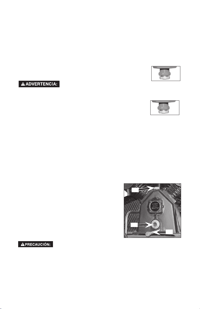
Cómo drenar el tanque
NOTA: L
de aire. Drene siempre el tanque sobre una superficie lavable o dentro de un contenedor apropiado,
con el objeto de prevenir daños o el manchado de superficies.
1. Coloque la palanca On/Auto/Off en la posición "Off".
2. Cierre la válvula de asiento.
3. Remueva la herramienta neumática o el accesorio.
4. Abra la válvula de asiento y lentamente deje purgar el aire del tanque de aire, hasta
5. Cierre la válvula de asiento.
6. Drene el agua contenida en el tanque de aire, abriendo la válvula
lo corroerá debilitando sus paredes, poniendo en riesgo la ruptura
del tanque de aire.
7. Una vez drenada el agua, cierre la válvula de drenaje. Ahora el
NOTA: Si la válvula de drenaje fuera del tipo enchufe, elimine toda
la presión de aire. La válvula podrá entonces ser extraída, limpiada y
finalmente reinstalada.
a operación del compresor de aire causa condensación que se acumula dentro del tanque
que la presión del mismo llegue aproximadamente a 20 PSI.
de drenaje ubicada en la base del tanque.
Riesgo de Explosión. El agua se condensa
dentro del tanque de aire. Si no se la drena,
compresor de aire podrá ser guardado.
Abra la válvula
de drenaje
Abra la válvula
de drenaje
Aceite
Utilice aceite específicamente formulado para uso en compresores, tal como el PorterCable PAS1 para compresores con aceite. El aceite podrá ser adquirido en el comercio
donde se haya comprado el compresor.
NOTA: La capacidad de aceite del cárter del cigüeñal es de aproximadamente 48 onzas fluidas (1,4
litros).
erificación
1. El nivel de aceite deberá llegar a la mitad del visor de vidrio (C).
2. En caso de necesidad quite el tapón de llenado de aceite (A) y agregue lentamente
aceite hasta alcanzar la mitad del visor de vidrio.
Cambio
1. Extraiga el tapón del aceite (A).
2. Extraiga del tapón de drenaje del aceite (B) y
drene el aceite en un recipiente adecuado.
3. Reponga el tapón de drenaje del aceite (B) y
ajústelo firmemente.
4.
Agregue aceite lentamente al compresor hasta que el nivel
alcance la mitad del visor de vidrio (C). NOTA: Al llenar el
cárter del cigüeñal, el aceite fluye muy lentamente dentro
de la bomba.
Si el aceite fuese agregado rápidamente rebalsará y aparentará
haberse llenado.
Riesgo de Operación Insegura.
No exceda su llenado.
5. Reponga el tapón del aceite (A) y ajústelo firmemente.
Sobrepasar el nivel de aceite causará la falla prematura del compresor.
A
C
B
68-SPA18791
Page 69
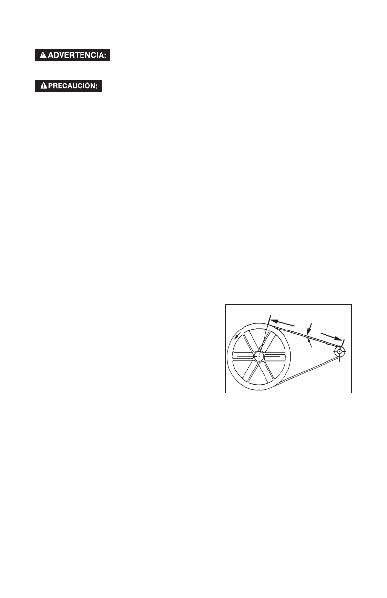
Filtro de aire - Inspección y reemplazo
Superficies calientes. Riesgo de quemaduras. Las cabezas del
compresor están expuestas cuando se retira la cubierta del
filtro. Deje enfriar al compresor antes de darle servicio.
Mantenga limpio el filtro de aire en todo momento. No haga
funcionar el compresor de aire sin su filtro de aire.
Un filtro de aire sucio no permitirá que el compresor opere a plena capacidad. Mantenga
el filtro de aire limpio en todo momento.
1. Extraiga el filtro de aire.
2. Retire la tapa del filtro de aire.
3. Extraiga el filtro de aire de la cubierta.
IMPORTANTE: No opere el compresor sin su filtro de aire.
4. Instale un nuevo filtro de aire dentro la cubierta del filtro. Para obtener el número de
pieza correcto, refiérase a "Piezas de reparación"
5. Reponga la cubierta del filtro del aire y rearme el filtro de aire a la bomba.
4. Afloje los tornillos montantes del motor y deslice éste hacia el compresor.
5. Retire la correa y reemplácela por una nueva.
6. Vea "Regulación de la tensión de la correa" antes de ajustar los tornillos montantes
del motor.
Regulación de la Tensión de la Correa
1. Deslice el motor a su posición original; alinéelo con la marca efectuada antes sobre
el montante.
2. Ajuste los dos tornillos exteriores del motor, lo suficiente para sostener a éste en
posición hasta verificar la alineación de la polea y el volante.
3. La correa debe flexionarse 4,8 mm
(3/16 pulg.) en el punto medio de la distancia
entre la polea y el volante cuando en ese
punto se aplique una fuerza de 2,3 a 4,5 Kg (5
a 10 libras).
4. Una vez lograda la tensión adecuada, ajuste
los cuatro tornillos montantes. Vea el Manual
de partes para informarse acerca de las
especificaciones de torque.
NOTA: Una vez que la polea del motor ha sido
movida, a partir de su instalación original de fábrica, las ranuras del volante y la
polea deben alinearse dentro un rango de variación de 1,6 mm (1/16 pulg.), para
prevenir un excesivo desgaste de la correa. Verifique la alineación ejecutando el
siguiente procedimiento de alineación polea-volante.
Fuerza hacia abajo
Deflexión
Polea y volante – Alineación
NOTA:Una vez que la polea del motor ha sido movida, punto de su instalación original de
fábrica, las ranuras del volante y la polea deben alinearse dentro un rango de variación de
1,6 mm (1/16 pulg.), para prevenir un excesivo desgaste de la correa.
El volante del compresor de aire y la polea del motor deben estar en línea (en el mismo
plano) dentro de una variación de 1,6 mm (1/16 pulg.), para asegurar la retención de la
correa dentro de las ranuras del volante. Para verificar la alineación ejecute los siguientes
pasos:
69-SP A18791
Page 70
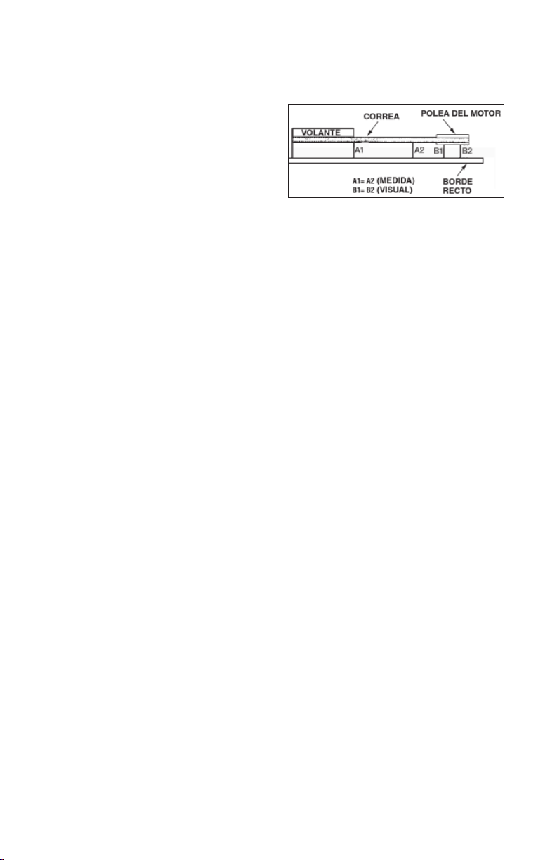
1. Apagar el compresor de aire, desconectar el suministro eléctrico, y liberar toda
presión de aire dentro del tanque.
2. Remueva la defensa de la correa.
3. Coloque una regla contra el lado exterior del volante y la polea de empuje del motor.
4. Mida la distancia entre el borde de la
correa y la regla, en el punto A1-A2 de la
figura. La diferencia entre las mediciones
no debe ser mayor que 1,6 mm (1/16
pulg.).
5. Si la diferencia es mayor que
1,6 mm (1/16 pulg.), afloje el tornillo de
fijación que sostiene la polea propulsora
del motor al eje y regule la posición de la polea en el eje hasta que las medidas A1 y
A2 se encuentren a 1,6 mm (1/16 pulg.) entre sí.
6. Ajuste los tornillos de fijación de la polea del motor. Vea el Manual de partes para
informarse de las especificaciones de torque.
7. Verifique visualmente que la polea de empuje del motor esté perpendicular al eje
del mismo. Los puntos B1 y B2 de la figura deben parecer iguales. Si así no fuera,
afloje el juego de tornillos de fijación de la polea de empuje del motor e iguale B1 y
B2, teniendo cuidado de no alterar la alineación de la correa ejecutada en el paso 2.
8. Reajuste los tornillos de fijación de la polea de empuje del motor vea el manual de
piezas para informarse de las especificaciones de torque.
9. Reinstale la defensa de la correa.
Válvulas de entrada y salida de la bomba del compresor de aire
Una vez al año haga que un técnico capacitado de servicio inspeccione las válvulas de
entrada y salida de la bomba del compresor de aire.
Inspección de las cañerías de aire y las conexiones para detectar
fugas
1. Ponga en marcha el compresor de aire para permitir inspeccionar la existencia de
fugas de aire.
2. Aplique una solución jabonosa a todos los acoplamientos de aire y las conexiones /
cañerías.
3. Corrija cualquier pérdida encontrada.
IMPORTANTE: Incluso pérdidas menores, pueden causar una carga adicional de trabajo
al compresor, dando como resultado su rotura prematura o una performance inadecuada.
Tornillos del cabezal del compresor de aire. - Torque
Los tornillos del cabezal del compresor de aire deben mantenerse debidamente
ajustados. Verifique el torque de los tornillos del cabezal luego de las primeras cinco
horas de operación. Reajústelos si fuese necesario. Vea el Manual de partes para
informarse de las especificaciones de torque.
70-SPA18791
Page 71
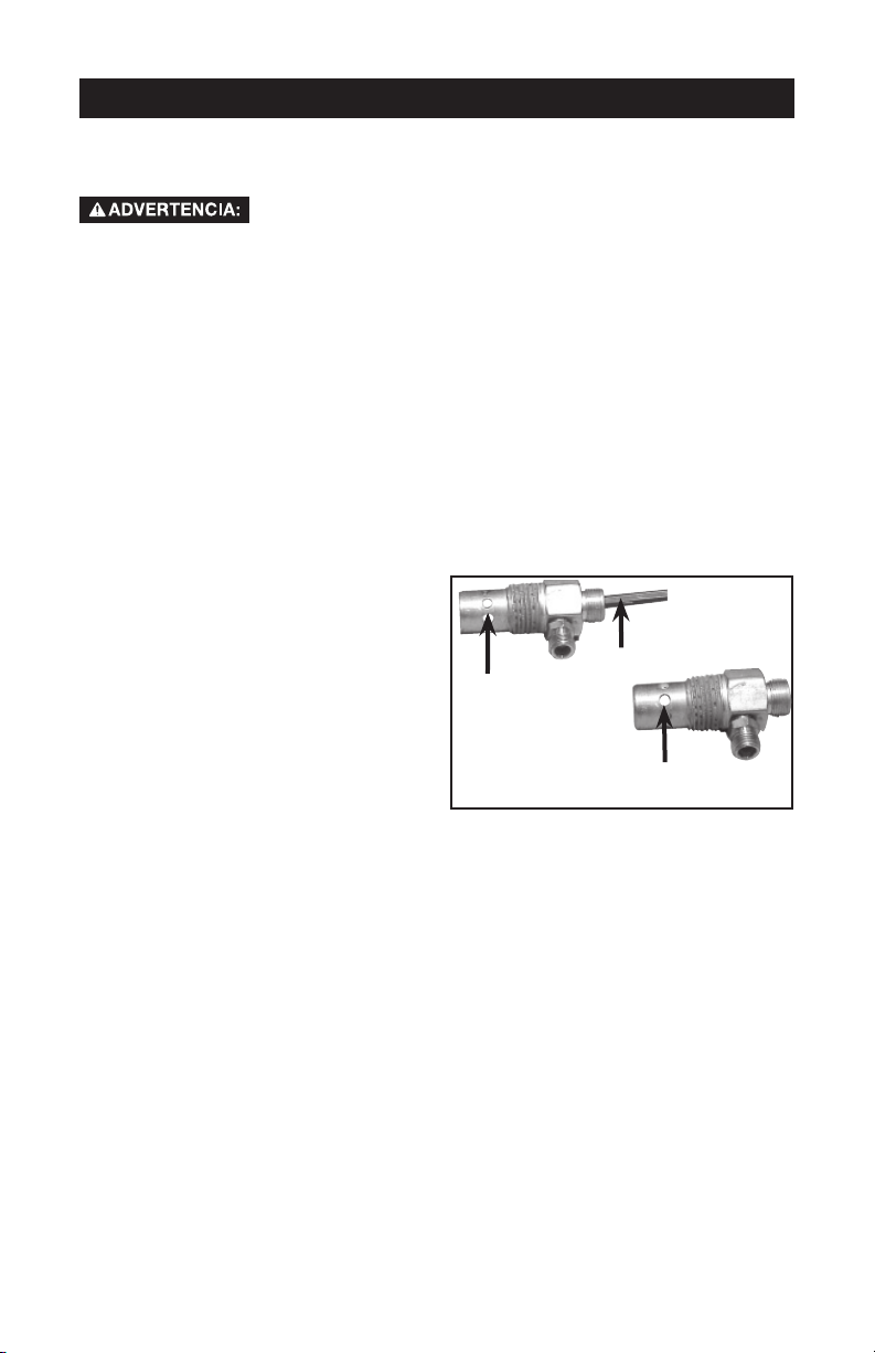
SERVICIO Y AJUSTES
TODO TIPO DE MANTENIMIENTO Y REPARACIONES NO MENCIONADOS EN
ESTE MANUAL, DEBERÁN SER EFECTUADOS POR PERSONAL TÉCNICO
ESPECIALIZADO.
Riesgo de Operación Insegura. La unidad arranca
mantenimiento, el operador puede quedar expuesto a fuentes de corriente y
de aire comprimido o a piezas movibles. Antes de intentar hacer reparaciones,
desconectar el compresor del tomacorriente, drenar la presión de aire del tanque y
esperar a que el compresor se enfríe.
Para reemplazar o limpiar la válvula de retención
1. Libere toda la presión del tanque de aire. Vea "Cómo Drenar el Tanque" en la
sección Mantenimiento.
2. Desenchufe el equipo.
3.
Utilizando una llave regulable, afloje la tuerca del tubo de salida del tanque de aire y la
bomba. Retire cuidadosamente la tubería de salida de la válvula de retención
4. Utilizando una llave regulable, afloje la tuerca del tubo aliviador de presión en el
tanque de aire y el interruptor de presión. Retire cuidadosamente la tubería de alivio
de presión de la válvula de retención.
5. Desenrosque la válvula de retención girándola hacia la izquierda usando una llave de
boca de 22 mm (7/8 pulg.). Tome nota de la orientación para volverla a ensamblar.
6. Usando un destornillador, empuje con
cuidado el disco de la válvula hacia
arriba y hacia abajo. NOTA: El disco
de la válvula debe moverse libremente
hacia arriba y hacia abajo sobre un
resorte que detiene el disco de la
válvula en la posición cerrada. Si no lo
hace, la válvula de retención necesita
ser limpiada o reemplazada.
7. Limpie o reemplace la válvula de
retención. Un solvente, tal como un
removedor de pintura o de barniz
puede usarse para limpiar la válvula de
retención.
8. Aplique sellador a las roscas de la válvula de retención. Vuelva a instalar la válvula
de retención (gire a la derecha).
9.
Vuelva a instalar la tubería de alivio de presión. Ajuste las tuercas.
10. Vuelva a instalar la tubería de salida y ajuste las tuercas.
11. Ejecute el procedimiento de puesta en marcha. Vea "Procedimiento de Puesta en
Marcha" en la sección Operación.
Servicio Adicional
No se recomienda desarmar ni darle servicio a este compresor de aire más allá de lo
tratado en este manual. Si se requiere de servicios adicionales, contactarse con el Centro
de Servicios de Garantía Autorizado más cercano.
automáticamente cuando está enchufada. Al hacer el
.
Destornillador
En posición
abierta
nada es
visible
En posición cerrada
el disco es visible
71-SP A18791
Page 72

ALMACENAJE
Antes de guardar su compresor de aire, asegúrese de hacer lo siguiente:
1. Revise la sección Mantenimiento de las páginas precedentes y ejecute el
mantenimiento programado de acuerdo a la necesidad.
2. Coloque la palanca On/Auto/Off en la posición "Off".
3. Cierre la válvula de asiento
4. Extraiga la herramienta neumática o el accesorio.
5. Abra la válvula de asiento y lentamente deje purgar el aire del tanque de aire, hasta
que la presión del mismo llegue aproximadamente a 20 PSI.
6. Drene el agua del tanque de aire abriendo la válvula de drenaje ubicada en el fondo
del tanque.
El agua se condensa dentro del tanque de aire. Si no se drena,
originando un riesgo de ruptura de sus paredes.
7. Una vez que el agua haya sido drenada, cierre la válvula de drenaje.
NOTA: Si la válvula de drenaje estuviese enchufada, libere toda la presión de aire. La
válvula podrá ser extraída, limpiada y luego reinstalada.
8. Proteja la manguera del aire de daños (tales como ser pisoteada o caminar por
encima).
Almacene el compresor de aire en un sitio limpio y seco.
ella corroerá debilitando las paredes del tanque de aire,
72-SPA18791
Page 73
GUÍA DE DIAGNÓSTICO DE PROBLEMAS
Riesgo de Operación Insegura. La unidad arranca automática-
operador puede quedar expuesto a fuentes de corriente y de aire comprimido o a
piezas movibles. Antes de intentar hacer reparaciones, desconectar el compresor
del tomacorriente, drenar la presión de aire del tanque y esperar a que el compresor
se enfríe.
PROBLEMA
Presión excesiva
del tanque - la válvula de seguridad
se dispara.
mente cuando está enchufada. Al hacer el mantenimiento, el
CAUSA
El interruptor de presión no
interrumpe al motor cuando el
compresor alcanza la presión
"de corte".
CORRECCIÓN
Mueva la palanca On/Auto/Off
a la posición "Off", si el equipo
no corta, contacte a un técnico
calificado para el servicio.
Las conexiones
pierden aire
Hay fugas de
aire en la válvula
de retención o
dentro de ella.
Pérdida de presión
de aire en el
interruptor de la
válvula aliviadora.
Pérdida de aire en
el tanque de aire o
en las soldaduras
del tanque de aire.
El interruptor de presión "de
corte" esta calibrado demasiado
alto.
Las conexiones de los tubos no
están suficientemente ajustadas
Compruebe si el asiento de la
válvula está dañado.
Un interruptor de presión defectuoso libera la válvula.
Tanque de aire defectuoso. El tanque de aire debe ser reem-
Contacte a un técnico de servicio
calificado.
Ajuste las conexiones en las que
el aire puede ser escuchado
escapándose. Verifique las conexiones con solución jabonosa y
agua. NO SOBREAJUSTE.
Una válvula de retención defectuosa causa una fuga constante
de aire en la válvula de alivio de
presión cuando hay presión en el
tanque y se apaga el compresor.
Reemplace la válvula de retención. Consulte "cómo reemplazar
o limpiar la válvula de retención"
en la sección Operación.
Contacte a un técnico calificado
en servicio.
plazado. No repare la perdida.
Riesgo de
Explosión.
No efectúe perforación alguna
sobre la soldadura o cosa
semejante sobre el tanque de
aire, ello lo debilitará. El tanque
podría romperse o explotar.
Pérdida de aire
entre el cabezal
y el plato de
válvula.
Pérdida en el sellado. Contacte a un técnico calificado
en servicio.
73-SP A18791
Page 74

PROBLEMA
La lectura de la
presión sobre un
manómetro (si viene equipado con
éste) desciende
cuando se utiliza
un accesorio.
CAUSA
Es normal que ocurra "algún"
descenso en la presión.
CORRECCIÓN
Si hubiese una caída excesiva de
presión durante el uso del accesorio, ajuste el regulador de acuerdo
a las instrucciones de la sección
Operación.
regulada bajo condiciones de flujo
(mientras se esté usando el accesorio).
NOTA: Ajuste la presión
Pérdida de aire
en la válvula de
seguridad.
El compresor no
esta suministrando suficiente
cantidad de aire
para
operar los accesorios
.
Posible defecto en la válvula
de seguridad.
Excesivo y prolongado uso
del aire.
El compresor no tiene suficiente capacidad para el
requerimiento de aire al que
está sometido.
Orificio en la manguera
Válvula reguladora restringida.
Pérdida de aire.
Filtro de entrada de aire
restringido
Correa suelta.
Opere manualmente la válvula de
seguridad, extrayéndola por su
anillo. Si la válvula pierde, deberá
ser reemplazada.
Disminuya la cantidad de uso de
aire.
Verifique el requerimiento de aire
del accesorio. Si es mayor que
SCFM o la presión suministrada
por su compresor de aire, se
necesita un compresor de mayor
capacidad.
Verifique y reemplace si fuese
necesario.
Extraiga, limpie o reemplace.
Ajuste las conexiones.
Limpie o reemplace el filtro de
entrada de aire. No opere el compresor de aire sin el filtro. Consulte
el párrafo "filtro de aire" en la sección Mantenimiento.
Verifique la tensión de la corra, lea
Ajuste de la tensión de la correa,
en la sección Mantenimiento.
Toma de aire
restringida
Filtro de aire sucio
Limpie o reemplace. Ver el párrafo
"filtro de aire" en la sección Mantenimiento.
74-SPA18791
Page 75

PROBLEMA
El motor no
funciona.
CAUSA
El interruptor de protección de
sobrecarga del motor se ha
abierto.
La presión del tanque excede
la presión de "corte máximo"
del interruptor de presión.
La válvula de retención se ha
quedado abierta.
Conexiones eléctricas sueltas.
CORRECCIÓN
Deje enfriar el motor y el interruptor de sobrecarga se reajustará
automáticamente.
El motor arrancará automáticamente
cuando la presión del tanque caiga
por debajo de la presión de corte
máxima del interruptor de presión
Retire y limpie, o reemplace.
Compruebe la conexión de cableado dentro del interruptor de presión
y del área de la caja de terminales.
Posible motor o capacitor de
arranque defectuosos
Rociado de pintura en las partes internas del motor.
La válvula de liberación de
presión en el interruptor de
presión no ha descargado la
carga de presión.
Fusible quemado, disyuntor
abierto.
Haga inspeccionar por un técnico
capacitado de servicio.
Haga inspeccionar por un técnico
capacitado de servicio. No haga
funcionar el compresor en el área de
pintura por rociado. Vea la advertencia acerca de vapores inflamables
Purgue la línea empujando la
palanca en el interruptor de presión
a la posición "OFF" [Apagado]; si
la válvula no se abre, reemplace el
interruptor.
1. Inspeccione la caja de
fusibles para determinar si
hay fusibles quemados y
reemplácelos según sea necesario. Reajuste el disyuntor.
No use un fusible o disyuntor
con capacidad mayor que la
especificada para su circuito
especificado.
2. Compruebe si el fusible es el
correcto. Debe usar un fusible
de acción retardada.
3. Compruebe si existen condiciones de bajo voltaje y/o si
el cordón de extensión es el
correcto.
4. Desconecte todos los otros
artefactos eléctricos del
circuito u opere el compresor
en su propio circuito.
Salta la válvula
de seguridad
El interruptor de presión,
la válvula de retención o la
bomba pueden estar necesitando mantenimiento.
75-SP A18791
Contacte a un técnico calificado en
servicio.
Page 76

PROBLEMA
Golpeteo
Excesivo
desgaste de la
correa.
CAUSA
Posible defecto en la válvula
de seguridad.
Posible defecto en la válvula
de seguridad.
Polea floja Ajuste el tornillo de la polea a ,Vea
Volante flojo Ajuste el tornillo del volante, Vea el
Tornillos montantes del compresor flojos
Correa floja
Acumulación de carbón en la
bomba.
Correa demasiado ajustada.
Correa suelta.
Correa demasiado ajustada.
CORRECCIÓN
Opere la válvula de seguridad
manualmente tirando de su anillo.
Si la válvula aun pierde, deberá ser
reemplazada.
Extraiga y limpie o reemplace.
el manual de piezas para conocer
las especificaciones de torque.
manual de piezas para conocer las
especificaciones de torque.
Ajustar los tornillos de montaje
a , Vea el manual de piezas para
conocer las especificaciones de
torque.
Verifique la tensión de la corra, lea
Ajuste de la tensión de la correa,
en la sección Mantenimiento.
Hágala verificar por un técnico
entrenado.
Verifique la tensión de la corra, lea
Ajuste de la tensión de la correa,
en la sección Mantenimiento.
Verifique la tensión de la corra, lea
Ajuste de la tensión de la correa,
en la sección Mantenimiento.
Verifique la tensión de la corra, lea
Ajuste de la tensión de la correa,
en la sección Mantenimiento.
Sonido a chiflido
Polea floja
Polea desalineada.
La bomba del compresor no
tiene aceite.
Correa suelta
76-SPA18791
Hágala verificar por un técnico
entrenado.
Ver el párrafo "alineación de polea/
volante del motor" en la sección
Mantenimiento.
Ver "verificacion del aceite" en la
sección Mantenimiento.
Verifique la tensión de la corra, lea
Ajuste de la tensión de la correa,
en la sección Mantenimiento.
Page 77

NOTES
77-SP A18791
Page 78

GARANTÍA LIMITADA
DeVilbiss Air Power Company garantiza al comprador original de esta unidad que la usa con fines no
comerciales (personales, residenciales o domésticos) contra defectos de materiales o de fabricación por
un año a partir de la fecha de su compra. Todas las unidades cubiertas bajo esta garantía utilizadas
comercialmente (p. ej.: para producir ingresos) están cubiertas contra defectos de materiales y de fabricación
por 90 días a partir de su fecha original de compra. Los equipos cubiertos por esta garantía incluyen
compresores de aire, herramientas neumáticas, repuestos, lavadoras de presión y generadores.
DeVilbiss Air Power Company, a su criterio, reparará o reemplazará, las unidades o componentes que
hubiesen fallado dentro del periodo de la garantía. El servicio se programará de acuerdo al flujo y horario
normal de trabajo del servicentro autorizado y a la disponibilidad de piezas de repuesto. Las decisiones de
DeVilbiss Air Power Company relacionadas con esta garantía limitada son definitivas.
Esta garantía le otorga derechos legales específicos y usted también podría tener otros derechos que varían
de un estado a otro.
RESPONSABILIDAD DEL COMPRADOR ORIGINAL (Usuario Inicial):
• Para procesar un reclamo bajo esta garantía, NO devuelva la unidad al lugar donde se compró. La unidad
debe evaluarse en un servicentro de garantías autorizado. Para ubicar el servicentro más cercano, llame
al 1-800-888-2468 durante las 24 horas del día, los 7 días de la semana, o visite nuestro sitio web en
www.devap.com.
• Conserve el recibo del pago original como comprobante de su compra para hacer reclamos cubiertos por
la garantía.
• Tener cuidado razonable al operar la unidad y darle mantenimiento según se describe en el Manual del
Propietario.
• Remita o entregue la unidad al servicentro de garantías autorizado más cercano. El costo de los fletes, si
alguno, debe pagarlo el comprador.
• Los compresores de aire con tanques de 227,1 l y 302,8 l serán inspeccionados en el lugar de la
instalación. Comuníquese con el servicentro de garantías autorizado más cercano que dé servicio a
domicilio para hacer los arreglos.
• Si el comprador no estuviese satisfecho con el servicio recibido del servicentro de Garantías Autorizado,
el comprador debe comunicarse con DeVilbiss Air Power Company.
ESTA GARANTÍA NO CUBRE:
• Mercadería vendida como reacondicionada, equipos usados para alquiler ni modelos de exhibición.
• Mercadería que se ha dañado o vuelto inoperante debido a su desgaste normal, uso inadecuado*, frío,
calor, lluvia, humedad excesiva, daños de congelamiento, uso con productos químicos inadecuados,
negligencia, accidente, operación sin seguir las instrucciones suministradas en el Manual del Propietario,
uso de accesorios o aditamentos no recomendados ni autorizados por DeVilbiss Air Power Company o
reparaciones o alteraciones no autorizadas.
* Un compresor de aire que bombea aire por más del ciclo recomendado dentro de una hora podría
considerarse que se usa indebidamente
• Los costos de reparación y transporte de mercadería determinada como no defectuosa.
• Los costos de ensamblaje, el aceite requerido, ajustes u otro gasto de instalación o puesta en operación.
• Piezas sujetas a desgaste que se proveen con la unidad y que se espera que se vuelvan inoperantes o
inusables después de un tiempo razonable, incluyendo, pero no limitándose a discos lijadores, hojas de
sierra y de cizalla, piedras de esmeril, resortes, cinceles, boquillas, anillos "O", boquillas de aire, arandelas
y accesorios similares.
• Mercadería vendida por DeVilbiss Air Power Company que ha sido fabricada por terceros e identificada
como tal; p. ej.: motores de gasolina. La garantía que se aplica, si alguna, es la de su fabricante.
• LAS PÉRDIDAS, DAÑOS O PERJUICIOS INCIDENTALES, INDIRECTOS O CONSECUENCIALES QUE
PUDIESEN RESULTAR DE CUALQUIER DEFECTO, FALLA O MAL FUNCIONAMIENTO DE LA UNIDAD
NO ESTÁN CUBIERTOS POR ESTA GARANTÍA. Algunos estados no permiten la exclusión o limitación
de los daños incidentales o consecuenciales, por lo que estas limitaciones o exclusiones podrían no
aplicarse a usted.
LAS GARANTÍAS IMPLÍCITAS, INCLUIDAS AQUELLAS DE COMERCIALIZACIÓN O IDONEIDAD PARA
UN PROPÓSITO PARTICULAR, ESTÁN LIMITADAS A UN AÑO A PARTIR DE LA FECHA ORIGINAL DE
COMPRA. Algunos estados no permiten limitaciones a la duración de las garantías implícitas, por lo que
estas limitaciones podrían no aplicarse a usted.
Jackson, TN EE.UU.
1-888-559-8550
78-SPA18791
 Loading...