

Page 1
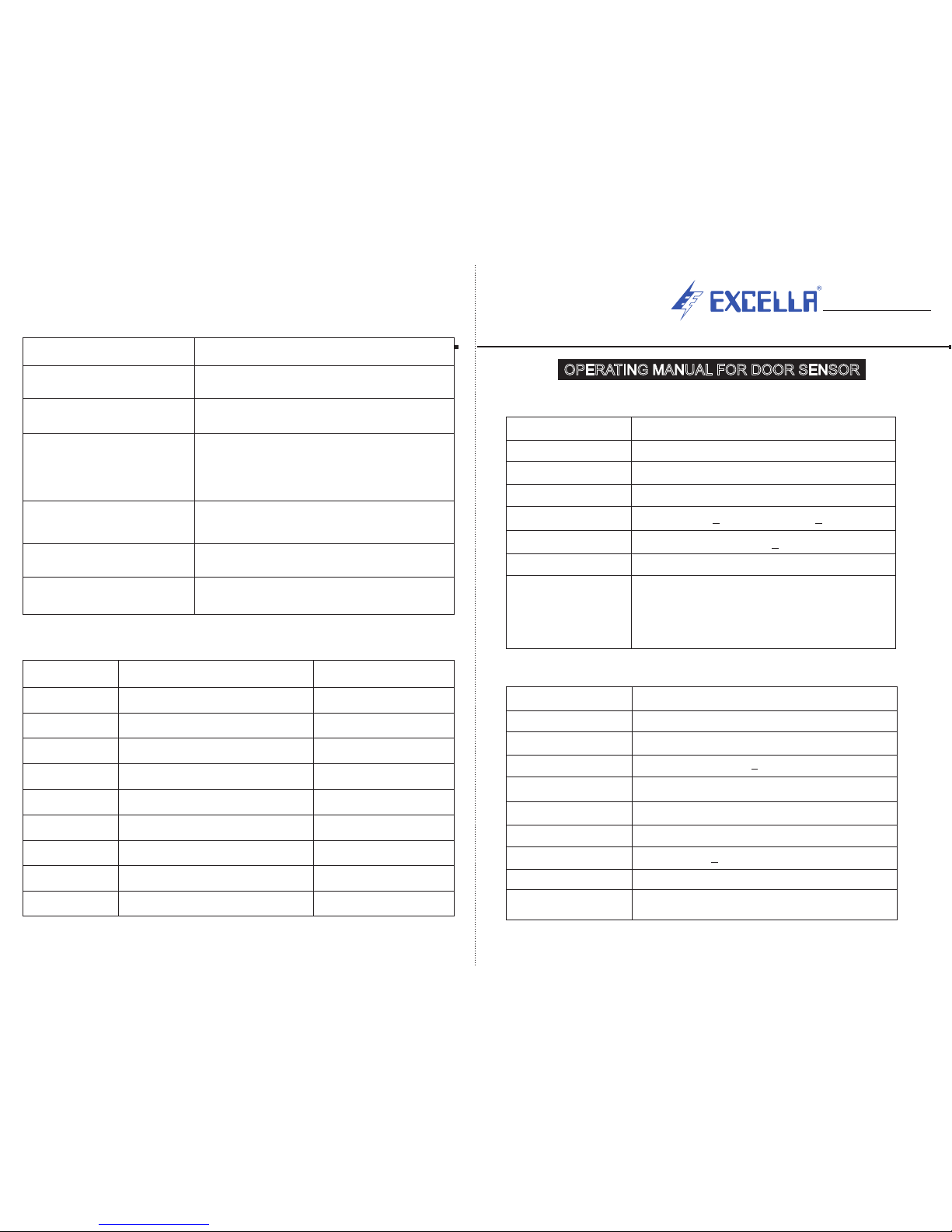
Model
Scanning beams
Detecting
Response time
Displacement at 0mm
Adaptive environment
Size (mm)
System Hint
E-2000
154 beams
0 ~ 4000mm
< 90ms
Vertical: 20mm; Horizontal: 3mm+ +
Light immunity 100000 lux>
9 X 24 X 2000
1. The green LED on the Receiver indicates the
normality of the sensors.
Slow flashing means it is in condition of timeout.
2. The red LED light in the Receiver indicates the
states of the sensors. If it is off, that means the
sensor is normal; If it is on or flashing, that means
the light curtain is obstructed or it arises errors.
1) Specification of Transmitter (TX) and Receiver (RX):
Control Box
External Dimension
Material
Input Voltage
Relay Output Type
Power Consumption
Lifetime of Relay
Short Circuit Protection
System Hint
(Buzzers are optional)
P220-S (With Buzzer)
178mm X 67mm X 39.5mm
Steel & Aluminium
185-300V AC, + 10%, 50/60 Hz
COM, 1NO, 1NC
4VA
250VAC, 7A or 30VDC, 7A
> 1000000 times
YES
Give buzzer sound once interrupted.
Relay Contact Rating
2) Specification of Control Box (Power Supply):
Phenomenon of Fault
No response in RX (LED)
LED green light in RX is
flashing slowly and regularly
Faults Analysis
Cables no connection; or control box no power;
or cables were snapped
System is in status of timeout; or the broken
diode will be ignored.
6) Faults Comparison Table:
Check if there are other infrared equipments
around; if the windows of TX and RX are dirty;
if the windows are shined by glare; if the
cables are bad, or the light curtains damaged.
The light curtain is not
obstructed, but both the
LED green and red lights in
RX are on.
LED lights in RX are normal, but
the door doesn"t open although
the light curtains are obstructed.
Red indicator light in Control
box is off.
When the door is closing, the
doors jump and re-open.
Wrong connection of control box, or relay output
is damaged, or the triode in RX is damaged.
Wrong connection in control box, or no power; or
connection is not tigtt; or control box damaged.
Not reasonable when wiring; or conductive
earth of the control box is not well
Item number
Item Name
7) Packing List:
Quantity
Control box
Cable (4m)
Transmitter (TX)
Receiver (RX)
Instruction book
25mm X 25mm cable clip
M3 X 25 Screw
M3 Nut
90mm Nylon ties
1.
2.
3.
4.
5.
6.
7.
8.
9.
1 PC
2 PC
1 PC
1 PC
1 PC
6 PC
10 PC
10 PC
6 PC
E L E C T R O N I C S
Tel.: Fax.:+91-22-21029911 +91-22-21029922!
! !E-mail: Web:[email protected] www.excellaelectronics.com
OPERATING MANUAL FOR DOOR SENSOR
Page 2
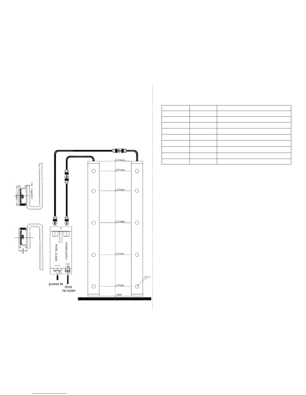
POWER SUPPLY UNIT:
MODEL P20 : INPUT 220V AC
CONNECTION:
4/6: POWER INPUT
1/3: N/C COM
2/3: N/O COM
LED STATUS :
RED LED : POWER INDICATION
GREEN LED : STATUS INDICATION
OFF : OBSTRUCTED OF ERROR
ON : NORMAL SCANNING
5) Installation Steps:
A.
B.
C
D.
First, the Transmitter (TX) and Receiver (RX) should be fixed on the two
sides fo the elevator door according to the standard fixing kit we provide. The
RX had better been fixed on the side that is less affected by sunshine.
The control box should be fixed on the top of the elevator cabin. The TX
and RX be joined with the control box by two signal cables, and the cables
should be fixed firmly and properly with Cable clips. When wiring the cables,
redundant cables could be packaged into loops with the Nylon ties, please keep
them away from other cables to avoid possible electromagnetic interface.
. After correct installation, the system can be turned on the power to run.
When the light curtain is not obstruncted by some object, both the green and
red LED light in RX are on or flashing, meanwhile, the relay loop will be no
power.
Daily Maintenance:
1) Please keep the external surface of the light curtain clean,
especially keep the light filter plats clean and avoid attaching
eyewinker on it, which will influence the receiving of the
infrared lights.
2) Frequently inspect the connection status of cables, Cable clips,
power wires and signal wires.
3) Please avoid putting water into light curtains.
Green LED
Red LED
Possible Cause
Fast Flashing
OFF
Normal Scanning
OFF
OFF
OFF
OFF
OFF
ON
ON
ON
ON
ON
Slow Flashing
FLASHING
FLASHING
FLASHING
FLASHING
FLASHING
No power, check power supply and cables.
TX / RX Connection Open Circuit
Some diodes have been timed out
Cable Shot Circuit
First PCB beams broken
Second PCB beams broken
Third PCB beams broken
Fourth PCB beams broken
4) The states of indicator lights on Receiver (RX):
The RX detector has two LED lights for troubleshooting:
3) Door Sensor Model E-2000 INSTALLATION
 Loading...