

EX-2001 Plus v1.3 SME300000060
EXCELL PRECISION CO., LTD.
© Excell Precision Limited 2004. All rights reserved Worldwide.
The information contained herein is the property of Excell Precision Limited
and is supplied without liability for errors or omissions. No part may be
reproduced or used except as authorised by contract or other written
permission. The copyright and the foregoing restriction on reproduction
and use extend to all media in which the information may be embodied.


EX-2001 Plus v1.3 SME300000060
1
EXCELL PRECISION CO., LTD.
TABLE OF CONTENTS
SAFETY............................................................................................................3
CHAPTER 1 SPECIFICATIONS.......................................................................4
CHAPTER 2 OPERATION GUIDE....................................................................5
CHAPTER 3 FRONT AND REAR PANEL........................................................7
3-1 FRONT PANEL.........................................................................................7
3-2 REAR PANEL...........................................................................................8
CHAPTER 4 INSTALLATION...........................................................................9
4-1 LOAD CELL.................................................................................................9
4-2 INDICATOR INSTALLATION AND DIMENSIONS.................................................9
CHAPTER 5 CAPACITY CALIBRATION........................................................11
5-1 PARAMETER SETTING.........................................................................11
5-1-1 Flow Diagram........................................................................................................11
5-1-2 Description...........................................................................................................12
5-2 CALIBRATION SETTING.......................................................................14
5-2-1 Calibration Procedure..........................................................................................14
5-2-2 Zero Calibration...................................................................................................14
5-2-3 Weight Calibration................................................................................................14
5-2-4 Linearity Calibration.............................................................................................15
5-3 PASSWORD SETTING..........................................................................18
5-4 ERROR MESSAGES.............................................................................19
CHAPTER 6 ANIMAL SCALE FUNCTION SETTING.....................................20
CHAPTER 7 INTERFACES............................................................................21
7-1 OP-01 RS-422 & RS-485 INTERFACE...................................................21
7-2 OP-02 PARALLEL BCD OUTPUT...........................................................24
7-3 OP-03 ANALOGUE CURRENT / VOLTAGE OUTPUT INTERFACE........26
7-4 OP-05 PARALLEL PRINTER OUTPUT & RS-232 & CURRENT LOOP...27
7-5 OP-06 RS-232 & CURRENT LOOP........................................................30
7-6 OP-07 RS-232, CURRENT LOOP & DATA CLOCK OUTPUT.................31
7-7 OP-08 CONTROL I /O (2I /4O) INTERFACE...........................................32
CHAPTER 8 MAINTENANCE........................................................................36
8-1 RESET ALL PARAMETERS BACK TO DEFAULT...................................36
8-2 RESET GENERAL FUNCTION PARAMETERS BACK TO DEFAULT.....36
8-3 SELF-DIAGNOSIS MODE......................................................................36
8-3-1 7 Digit Display and LED Status Light Diagnosis................................................37
8-3-2 Keyboard and Calibration ON / OFF Switch Diagnosis.....................................37
8-3-3 RS-232 Serial Output / Input Interface Diagnosis ( OP-06 )..............................37

EX-2001 Plus v1.3 SME300000060
2
EXCELL PRECISION CO., LTD.
8-3-4 BCD Parallel Output Interface Diagnosis ( OP-02 )...........................................37
8-3-5 Analogue Current Output Interface Diagnosis ( OP-03 )...................................38
8-3-6 Parallel Printer Interface Diagnosis ( OP-05 )....................................................38
8-3-7 Main Board EEPROM Memory Diagnosis.........................................................38
8-3-8 OP-08 Control I /O (2I /4O) Diagnosis...............................................................38
CHAPTER 9 FUNCTION TABLE....................................................................39
9-1 GENERAL FUNCTION...........................................................................39
9-2 OP-01, OP-06, OP-07 INTERFACE FUNCTION.....................................40
9-3 OP-02 BCD OUTPUT INTERFACE FUNCTION.....................................41
9-4 OP-03 ANALOGUE OUTPUT INTERFACE FUNCTION.........................41
9-5 OP-05 PARALLEL PRINTER OUTPUT INTERFACE FUNCTION...........42
9-6 OP-08 CONTROL I /O (2I /4O) INTERFACE FUNCTION........................43

EX-2001 Plus v1.3 SME300000060
3
EXCELL PRECISION CO., LTD.
!
rSAFETY
& Disconnect the main power supply before opening the indicator housing or
installing / un-installing the instrument.
& Keep the instrument in a cool dry place. Do not store it at high
temperatures.
& The operating ambient temperature range is -10°C ~ +40°C.
& F.G. is the ground (electrical earth) connection. (Ground impedance < 100Ω)
Avoid connecting the ground connection with other equipment. The
indicator must always be connected to the electrical ground (earth) for safe
operation.

EX-2001 Plus v1.3 SME300000060
4
EXCELL PRECISION CO., LTD.
CHAPTER 1 SPECIFICATIONS
ANALOG DATA
Input sensitivity 0.12 μV/D or more
Max. load cell input voltage -1mV〜16mV
Load cell excitation DC 5V
Load cell current 120mA ( 8- 350Ω load cells )
Zero -14.49 ppm/℃ ( -10℃〜40℃)
Temperature coefficient
Span
-1.65 ppm/℃ ( -10℃〜40℃)
Non-linearity ±0.002%FS
Input noise 8nV⁄√Hz f = 10KHz
Input impedance 250GΩ
Internal resolution 520000
Max. display resolution -999999〜999999
Conversion rate 100 times/sec (max.)
DIGITAL DATA
Display section 7 digits, red LED, 20mm (0.8”), 7-segment
Status display section 6 character display, red LED
Display frequency (times/sec) Selectable, Max 50
Display range -999999 to 999999
Min. division 1, 2, 5, 10, 20, 50
Status display Power, Zero, Motion, Gross, Net, Tare
Decimal point Selectable 0, 0.0, 0.00, 0.000, 0.0000
GENERAL SPECIFICATIONS
Power requirements (AC/W)
AC100V〜240V -15%~+10% 10W
Operating temperature range
-10℃〜+40℃
Operating humidity range
<85% R.H
Physical dimensions 210(W) × 108 (H) × 207(D)
Weight About 1.7 kg
OPTIONS
OP-01 RS422 / RS-485
OP-2-1 Parallel BCD Output ( TTL )
OP-2-2 Parallel BCD Output ( O.C. )
OP-03 Analog Output ( 4 - 20mA )
OP-05 Parallel Printer Output / RS232C & Current Loop
OP-06 RS-232C & Current Loop
OP-07 RS-232C & Current Loop & Data Clock Output
OP-08 Control I / O ( 2I / 4O)
EX-2001 Plus v1.3 SME300000060
5
EXCELL PRECISION CO., LTD.
Fn
Fn
Fn
CAL
CAL
Fn
CAL
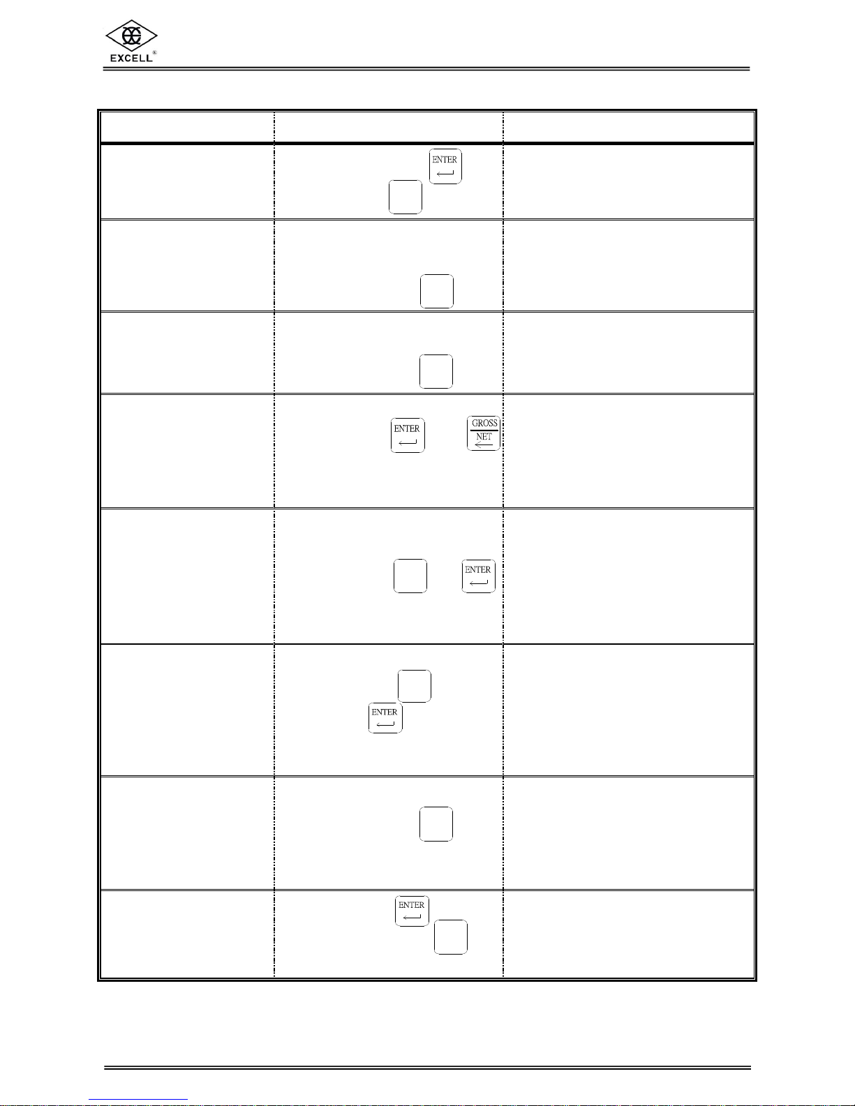
CHAPTER 2 OPERATION GUIDE
FUNCTION OPERATION PROCEDURE DESCRIPTION
General function
setting
Press and hold the key,
then press the
Refer to Chapter 9
Functions Table
to set FUNC. 0 ~ FUNC. 7
Capacity parameter
setting
Switch the capacity calibration
switch to “ON”
and then press the
Set the parameter for decimal
point, max. capacity, min. division,
zero tracking, unstable detection
Refer to < 5-1 > Parameter Setting
Calibration
Switch the capacity calibration
switch to “ON”
and then press the
Calibration procedures.
Refer to < 5-2 > Calibration Setting
Self-diagnosis mode
Turn on the indicator,
press and hold and
the indicator starts the self-test
procedure.
Refer to < 8-3 > Self-diagnosis
Mode for details
Reset all parameters
back to default
Switch the calibration switch to
“ON”, turn on the indicator,
press and hold and
while the indicator is in the
self-testing sequence
Refer to < 8-1 > Reset All
Parameter Back to Default
Reset general function
parameter back to
factory standard setting
Turn on the indicator,
press and hold
, followed
by pressing
while the indicator is in the
self-testing sequence
Refer to < 8-2 > Reset General
Function Parameter Back to
Default
Display software version
Turn on the indicator,
press and hold the
while the indicator is in the
self-test sequence
The main display section displays
the software version,
press any key
to exit
Function parameter
setting
Press and hold ,
followed by pressing
Hi, Lo, Zero Band parameter
setting

EX-2001 Plus v1.3 SME300000060
6
EXCELL PRECISION CO., LTD.
4 Operation of Keys in the Setting Mode
⇒ Cycles the flashing character from 0 to 9 ⇒ Shifts the flashing character to the left
⇒ Cycles the flashing character from 9 to 0 ⇒ Save data
⇒ Shifts the flashing character to the right ⇒ Quit / Exit
EX-2001 Plus v1.3 SME300000060
7
EXCELL PRECISION CO., LTD.
Fn
CAL
POWERZEROGROSSMOTION
NETTARE ENTERED
Racer
1
2
3
4
ON
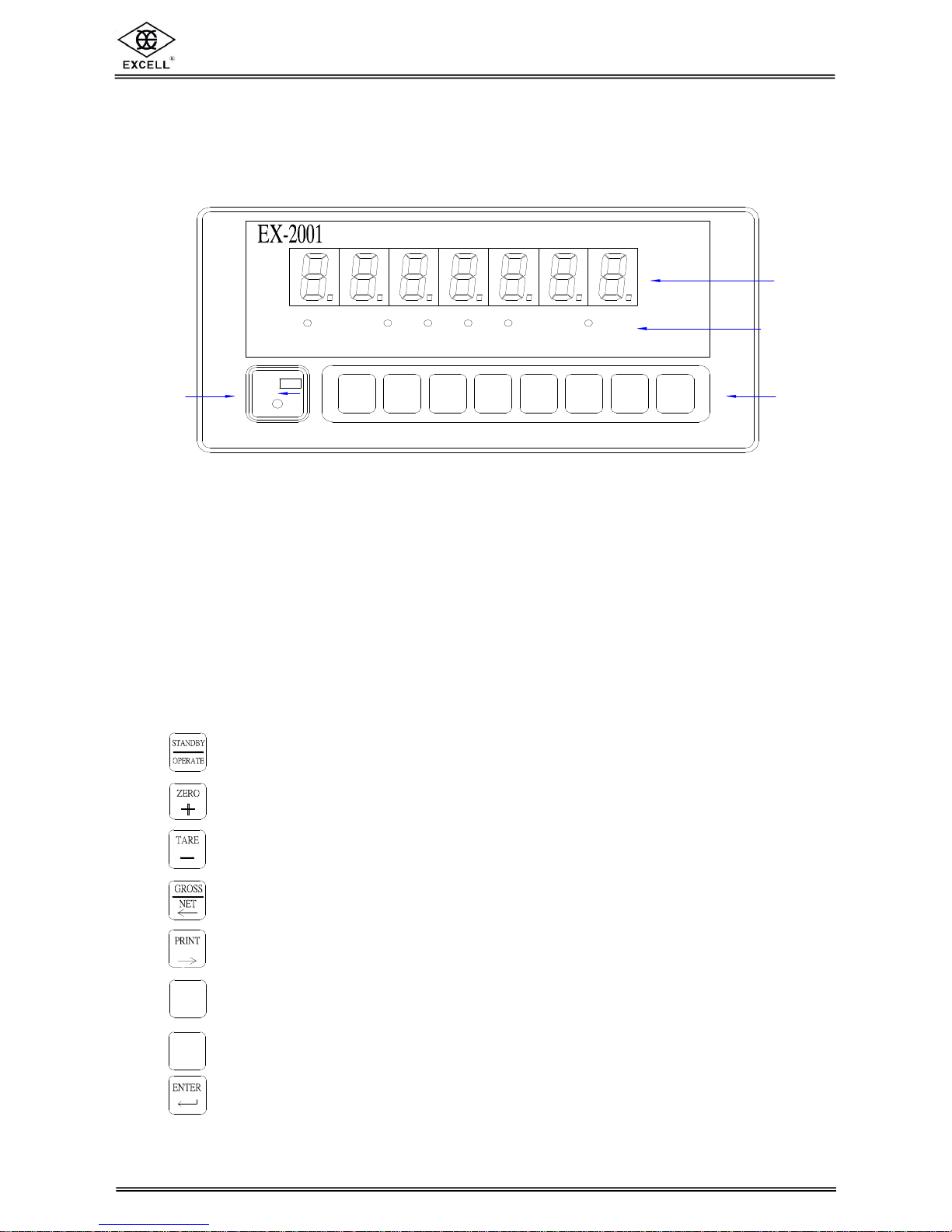
CHAPTER 3 FRONT AND REAR PANEL
3-1 FRONT PANEL
1 MAIN DISPLAY
• Displays gross weight or net weight
2 STATUS INDICATION LIGHTS
☼ POWER : Power Indication
☼ ZERO : Zero status indication
☼ MOTION : Unstable weighing indication
☼ GROSS : Main display section currently displays gross wt.
☼ NET : Main display section currently displays net wt.
☼ TARE ENTERED : Tare indication
3 KEYS
1) Standby mode ON/OFF
2) When setting the parameter or calibration, it works as quit or exit from setting
1) Sets weight back to zero
2) When setting the parameter or calibration, it cycles from 0 to 9
1) Tare function
2) When setting the parameter or calibration, it cycles from 9 to 0
1) Switches between gross wt. / net wt. on the main display
2) When setting the parameter or calibration, it shifts the flashing character to the left
1) Manually output serial / parallel data
2) When setting the parameter or calibration, it shifts the flashing character to the right
1) Weight accumulation, sub-total function (for OP-05)
2) Sets capacity parameter
1) Weight accumulation, grand-total function (for OP-05)
2) Capacity calibration
Confirmation key
Plus

EX-2001 Plus v1.3 SME300000060
8
EXCELL PRECISION CO., LTD.
DATA IN / OUT
LOAD CELL
FUSE/0.5A
AC 100V~240V
CONTROL IN / OUTPUT
2 1 C2 C1
4
3 2 1
OUTPUTINPUT
before opening the covers.
Isolating the ac power
! WARNING
12
3
4
5
4 CAPACITY PARAMETER & CALIBRATION SWITCH
Loosen the black plastic screw and open the square cap on the front panel.
Slide the switch to the left is “ON”
Slide the switch to the right is “OFF”
3-2 REAR PANEL
1. AC power in terminal
2. Fuse 250V / 0.5A
3. Load cell connector
4. Optional interface location (if fitted)
5. Control I/O Interface location
EX-2001 Plus v1.3 SME300000060
9
EXCELL PRECISION CO., LTD.
6
1
2
8
7
5
4
3
Load cell
Load cell cable
Shield
SEN+
SIG-SIG+
EXC+
EXCSEN-
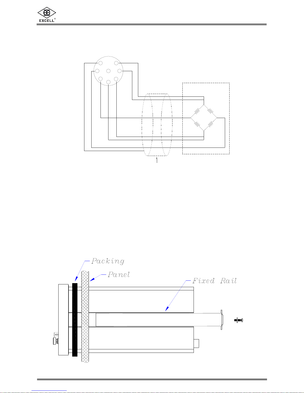
CHAPTER 4 INSTALLATION
4-1 LOAD CELL
Four-wire (five-wire) load cell Six-wire (seven-wire) load cell
Pin 1 & 2 short, connected to EXC+ Pin 1 connected to EXC+
Pin 3 & 4 short, connected to EXC- Pin 2 connected to SEN+
Pin 5 connected to SIG+ Pin 3 connected to EXCPin 6 connected to SIG- Pin 4 connected to SENPin 7 connected to the Shield Pin 5 connected to SIG+
Pin 6 connected to SIG Pin 7 connected to the Shield
4-2 INDICATOR INSTALLATION AND DIMENSIONS
2 The indicator can be installed in a control panel as detailed below

EX-2001 Plus v1.3 SME300000060
10
EXCELL PRECISION CO., LTD.
! WARNING
before opening the covers.
Isolating the ac power
LOAD CELL
AC 100V~240V
IN / OUTPUT
2
FUSE/0.5A
CONTROL
INPUT
1 2
OUTPU T
4
C2 C1
3 1
DATA IN / OUT
Racer Plus
MOT IONPOW ER ZERO G RO SS NET ENTE REDTAR E
2 INDICATOR DIMENSIONS (measurement unit: mm)
EX-2001 Plus v1.3 SME300000060
11
EXCELL PRECISION CO., LTD.
Fn
CHAPTER 5 CAPACITY CALIBRATION
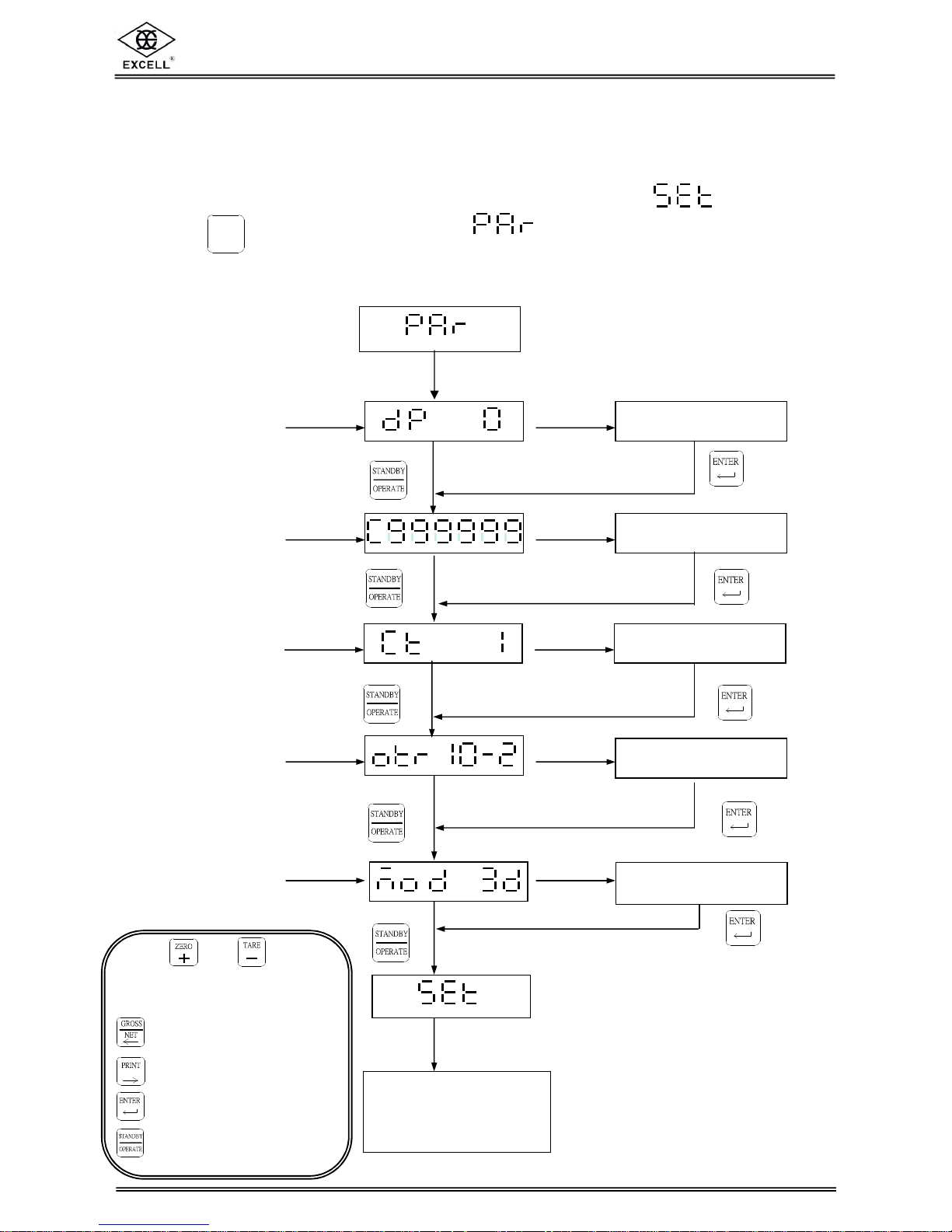
5-1 PARAMETER SETTING
Switch the capacity calibration switch to “ON” and the display shows .
Press the key and the display shows . then enter the setting mode.
Refer to 3-1 Front Panel for the key functions to set the relative parameters.
5-1-1 Flow Diagram
1.
2.
3.
4.
4.
5.
5.
.
Decimal Point
.
.
Setup completed
Max. Capacity
Setup completed
Min. Division
.
Setup completed
Zero Tracking
. .
.
Setup completed
Unstable
Detection
.
Switch the
calibration switch
to OFF
Setup completed
.
Using and keys to
choose the desired
settings
⇒ Shift the flashing digit
one space to left
⇒ Shift the flashing digit
one space to right
⇒ Save the settings
⇒ Exit the settings
EX-2001 Plus v1.3 SME300000060
12
EXCELL PRECISION CO., LTD.
5-1-2 Description
1) Decimal Point
Setting the weight decimal point position, with the following options: 0, 0.0, 0.00,
0.000, 0.0000.
2) Max. Capacity
Depending on the decimal point position, the max capacity can be set from 99.999
to 999999.
3) Min. Division
Depending on the decimal point position and the max capacity, the min. division
could be set as 1, 2, 5, 10, 20, 50.
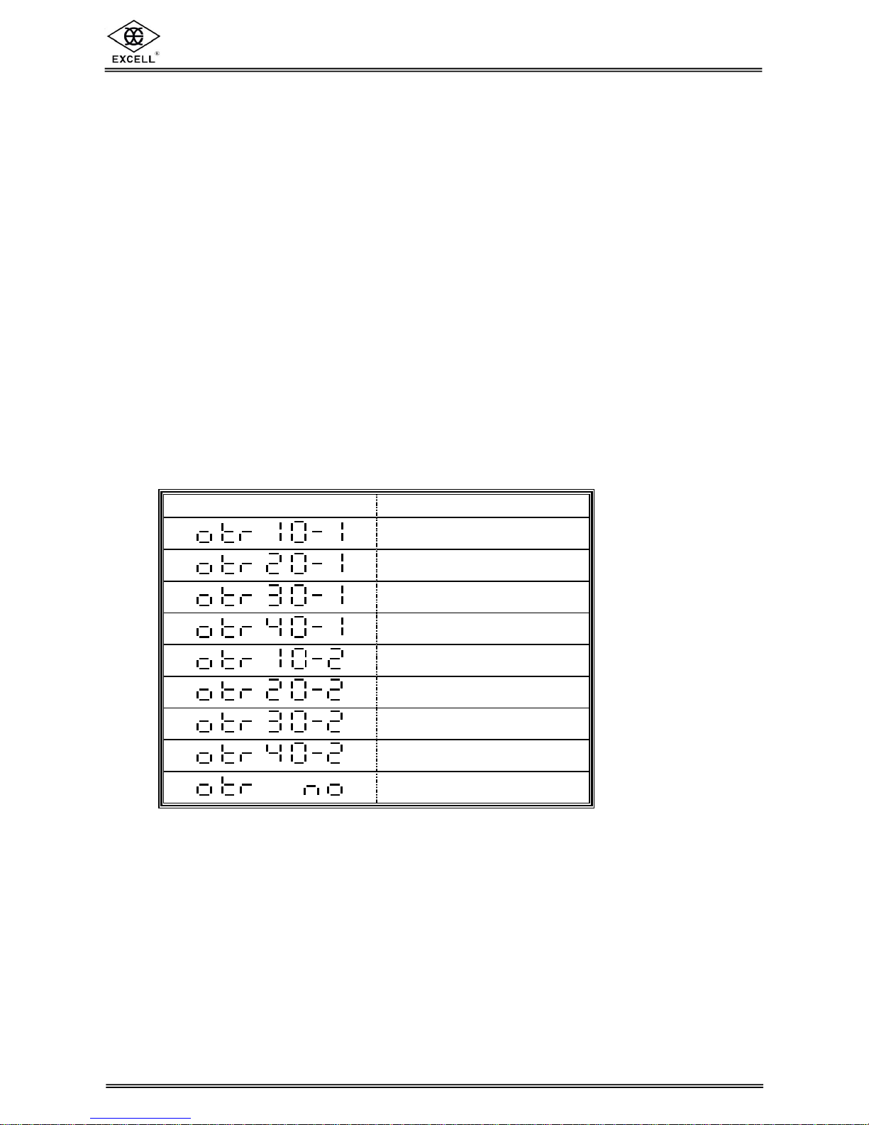
4) Zero Tracking
Display Division / Time
. . .
1 D / 1 sec
. . .
2 D / 1 sec
. . .
3 D / 1 sec
. . .
4 D / 1 sec
. . .
1 D / 2 sec
. . .
2 D / 2 sec
. . .
3 D / 2 sec
. . .
4 D / 2 sec
. .
No zero tracking

EX-2001 Plus v1.3 SME300000060
13
EXCELL PRECISION CO., LTD.
5) Unstable Detection
Display Division / Time
.
1 d / sec
.
2 d / sec
.
3 d / sec
.
4 d / sec
.
5 d / sec
.
No detection

EX-2001 Plus v1.3 SME300000060
14
EXCELL PRECISION CO., LTD.
CAL
5-2 CALIBRATION SETTING
Please allow the indicator to warm up at least 15 to 30 minutes before calibration.
Switch the capacity calibration switch to “ON” and the display shows .
Press the key and the display shows . then enter the setting mode.
5-2-1 Calibration Procedure
Zero Calibration
Weight Calibration
5-2-2 Zero Calibration
a) Make sure that there are no objects on the weighing platform and press
the key, after the indicator has stabilized the display will show
“ ……. ”. The calibration is completed after about 5 seconds.
b) To skip the “Zero calibration” procedure, press the key.
5-2-3 Weight Calibration
a) Place an accurate weight onto the platform; use the front panel keys to key in
the weight value. Press the key, after the indicator is stabilized the display will
show “ ……. ”. The calibration is completed after about 5 seconds.
b) To skip the weight calibration, press the .
Zero Calibration
Complete
d
Confirmation
completed
Switch the calibration
switch to OFF
Place
calibrated
weight
⇒ Increase the number of
the flashing digit
⇒ Decrease the number
of the flashing digit
⇒ Shift the flashing digit
one space to left
⇒ Shift the flashing digit
one space to right
⇒ Save the settings
⇒ Exit the settings

EX-2001 Plus v1.3 SME300000060
15
EXCELL PRECISION CO., LTD.
. . . . . .
Before linearity calibration, make sure “Zero calibration” and “Weight Calibration” are properly
performed. Set the calibration switch to ON position.
Press
CAL
key
Choose
Press
key
Press
to next step Press
key to previous step
Press
to next step Press
key to previous step
Enter the correct weight value
Press
to next step
The calibrated weight value
is displayed when the
signal is stable
Press
to next step
After finishing the first linearity calibration,
choose to continue or exit the linearity mode
by pressing
.
◆ Refer to 5-4 Error Messages when any error message appears during the procedure.
5-2-4 Linearity Calibration
Five point linearity calibration.
Choosing from 1P ~ 5P by
pressing
key.
⇒ No linearity
calibration value at this point
⇒ linearity calibration
value present at this point
The weight value is displayed.
⇒ Increase the number of
the flashing digit
⇒ Decrease the number
of the flashing digit
⇒ Shift the flashing digit
one space to left
⇒ Shift the flashing digit
one space to right
⇒ Save the settings
⇒ Exit the settings

EX-2001 Plus v1.3 SME300000060
16
EXCELL PRECISION CO., LTD.
Recall Linearity correction point
Set the calibration switch to ON position.
Press
CAL
key
Choose
Press
key
Press
key
Press
key
After finishing the first linearity calibration,
choose to continue or exit the linearity mode
by pressing
.
Five point linearity calibration.
Choosing from 1P ~ 5P by
pressing
key.
⇒ No linearity
calibration value at this point
⇒ Linearity
calibration value at this point
The weight value is displayed.
⇒ Increase the number of
the flashing digit
⇒ Decrease the number
of the flashing digit
⇒ Shift the flashing digit
one space to left
⇒ Shift the flashing digit
one space to right
⇒ Save the settings
⇒ Exit the settings

EX-2001 Plus v1.3 SME300000060
17
EXCELL PRECISION CO., LTD.
CAL
Clear a linearity correction point
Set the calibration switch to ON position.
Press key
Choose
Press
key
Press
key
Press
key
After finishing the first linearity calibration,
users can choose to continue or exit the
linearity mode by pressing
.
Five point linearity calibration.
Choosing from 1P ~ 5P by
pressing
key.
⇒ No linearity
calibration value at this point
⇒ Linearity calibration
value at this point
The weight value is displayed.
⇒ Increase the number of
the flashing digit
⇒ Decrease the number
of the flashing digit
⇒ Shift the flashing digit
one space to left
⇒ Shift the flashing digit
one space to right
⇒ Save the settings
⇒ Exit the settings

EX-2001 Plus v1.3 SME300000060
18
EXCELL PRECISION CO., LTD.
5-3 PASSWORD SETTING
Set the calibration switch to ON position.
Set the new password
* Enter “0000” to skip password
setting.
Confirm the password (re-
enter
the password again)
Press key
Press
key
Press
key
4 Once the password is set, whenever users access to the calibration mode or
the other function settings, the display shows
After I sec.
,
and users need to enter the password.
4 If the password is incorrect, . is displayed.
⇒ Increase the number of
the flashing digit
⇒ Decrease the number
of the flashing digit
⇒ Shift the flashing digit
one space to left
⇒ Shift the flashing digit
one space to right
⇒ Save the settings
⇒ Exit the settings

EX-2001 Plus v1.3 SME300000060
19
EXCELL PRECISION CO., LTD.
5-4 ERROR MESSAGES
(1) The output voltage of load cell is < - 0.1mV/V or > 4mV/V
(2) The weight setting value is not over the setting value of prior
section.
(3) The actual weight value is not over the value of prior section.
(4) The setting value is 0.
(5) Calibration resolution is less 0.12μV / d.
(6) . Incorrect password

EX-2001 Plus v1.3 SME300000060
20
EXCELL PRECISION CO., LTD.
CHAPTER 6 ANIMAL SCALE FUNCTION SETTING
2 FUNC. 8 = 1 (Animal scale function is active)
“
” is displayed, when there is no object on the weight panel:
The weight of live stocks is measured and showed in the display, (20 kg in this
example):
The weight value will be held until removing all the objects on the weight panel. When
the weight value is below zero band and display shows “ ” , the scale is
ready for another weighing operation.
.

EX-2001 Plus v1.3 SME300000060
21
EXCELL PRECISION CO., LTD.
DATA OUT
REAR PANEL
1
23
4
5
98
76
4
32
1
89
76
5
CHAPTER 7 INTERFACES
7-1 OP-01 RS-422 & RS-485 INTERFACE
2 OP-01 RS-422 / RS-485
With this interface up to 10 indicators can be connected together and data transferred
to a host controller.
FUNC. 70 should be set to “ 1 ”
2 Connector pin assignment
Pin number
Function
1 SDA
2 SDB
3 RDA
4 RDB
5 TRM
6
7
8
SG
9 RDB’

EX-2001 Plus v1.3 SME300000060
22
EXCELL PRECISION CO., LTD.
SDA
SDB
RDA
RDB
TRM(5)
SG
RDB'(9)
SDB(2)
SDA(1)
RDA(3)
SG(6.7.8)
RDB(4)
EX-2001#1
FUNC67=01
EX-2001#2
FUNC67=02
EX-2001#10
FUNC67=10
RDB'(9)
TRM(5)
SG(6.7.8)
RDB(4)
SDA(1)
SDB(2)
RDA(3)
RDB'(9)
TRM(5)
RDB(4)
SG(6.7.8)
RDA(3)
SDB(2)
SDA(1)
DA
DB
TRM(5)
SG
RDB'(9)
SDB(2)
SDA(1)
RDA(3)
SG(6.7.8)
RDB(4)
EX-2001#1
FUNC67=01
EX-2001#2
FUNC67=02
EX-2001#10
FUNC67=10
RDB'(9)
TRM(5)
SG(6.7.8)
RDB(4)
RDA(3)
SDB(2)
SDA(1)
RDB'(9)
TRM(5)
SG(6.7.8)
RDB(4)
RDA(3)
SDB(2)
SDA(1)
HOST COMPUTER
HOST COMPUTER
RS-422
RS-485
2 Connection method
4 Remark:
When connecting the last EX-2001 indicator, the fifth pin (TRM) and the ninth pin
(RDB’) should be connected together, excluding the following two conditions:-
♦ The host computer has a built-in terminator.
♦ The host computer does not have signal ground (SG).

EX-2001 Plus v1.3 SME300000060
23
EXCELL PRECISION CO., LTD.
2 Refer to Chapter 9 Function Table to set FUNC. 60 ~ FUNC. 67
2 Transmit format
S T
,
G S
,
+ 1 2 3 4
.
5 6 g CR LF
Header 1 Header 2 Weight Data ( 8 digits ) Units Terminators
Header 1
ST : Stable / US : Unstable / OL : Over Load
Header 2
GS : Gross weight / NT : Net weight / TR : Tare
Weight Data ( 8 digits )
The first digit is the + / - symbol for weight value. The next seven digits include
decimal point and weight value.
When the weight is over loaded ( Header 1 : OL ), all digits will be transmitted “blank”
(sp) except the + / - signal and the decimal point.
Units
Kg, g, t, lb or “blank”
Terminators
CR, LF is the data finish code.
2 Command mode
COMMAND FUNCTION
READ, RW Reads weight
ZERO, MZ Back to zero
TARE, MT Tare
NTGS Switches gross / net weight
MG Displays gross weight
MN Displays net weight
CT Clears tare
ΠThe command string must be terminated with CR ( 0DH ) , LF ( 0AH ).
• If a wrong command is received, the indicator will reply “E” + “ error command ”.
Ž If the command mode has been selected “with address”, (FUNC. 61 = 4)
then every command must be preceded with an indicator address in the format:-
“ @ address ”
Example: To read the weight value form indicator addressed as 01 (“01” selected in
FUNC. 67)
The complete command is @01RW<CR><LF>

EX-2001 Plus v1.3 SME300000060
24
EXCELL PRECISION CO., LTD.
REAR PENAL
DATA OUT
1
25
5026
7-2 OP-02 PARALLEL BCD OUTPUT
2 Pin assignment
BCD parallel output interface
uses Centronic 50 PIN connector
Pin number Function Pin number Function
1 SG 26 SG
2
1×10
27 Gross/-NET
3
2×10
28
4
4×10
29
5
8×10
30
6
1×10¹
31
7
2×10¹
32
8
4×10¹
33 Stable
9
8×10¹
34
10
1×10²
35
11
2×10²
36
12
4×10²
37
13
8×10²
38
14
1×10³
39
15
2×10³
40
16
4×10³
41
17
8×10³
42 POSITIVE
18
1×10
43 DP10¹
19
2×10
44 DP10²
20
4×10
45 DP10³
21
8×10
46 DP10
22
1×10
47 OVER
23
2×10
48
24
4×10
49 Data ready
25
8×10
50 Hold input

EX-2001 Plus v1.3 SME300000060
25
EXCELL PRECISION CO., LTD.
Signal out
SG
TTL Output
Signal out
SG
30mA(max.)
+30V(max.)
Open Collector
Output
SG
Hold Input
Signal in
+5V
Data output
Data ready
Hold
2ms
5ms
2 Refer to Chapter 9 Function Table to set FUNC. 80 ~ FUNC. 83
2 Output equivalent circuit
2 Hold Input
2 Output / Input signal description
ΠA total of 33 bit outputs are provided. To set the output logic level, refer to Chapter
9 FUNC 82 and FUNC 83.
• If Open Collector output is selected, an external resistor is required to limit the
current in the interface.
The voltage should not exceed 30Vdc and current should be less than 30mA.
Ž “Hold input” is the only one input signal. To activate the “Hold input”, just connect
the Hold input to SG signal. When Hold is working, all BCD outputs will be held
and cannot be altered.

EX-2001 Plus v1.3 SME300000060
26
EXCELL PRECISION CO., LTD.
DATA OUT
A- A+
DATA OUT
J1
7-3 OP-03 ANALOGUE CURRENT / VOLTAGE OUTPUT
INTERFACE
2 Connections
Interface specification
Analogue current output : 0 ~ 20 mA
Load resister : 0 ~ 550 Ω
Resolution : 12 bit
2 Refer to Chapter 9 Functions Table to set FUNC 85 ~ FUNC 89
2 Voltage output
J1 short if the voltage output is 0 ~ 10V.
J1 open if the current output is 4 ~ 20mA.

EX-2001 Plus v1.3 SME300000060
27
EXCELL PRECISION CO., LTD.
113
2514
1
2
3
4
7-4 OP-05 PARALLEL PRINTER OUTPUT & RS-232 & CURRENT
LOOP
2 Pin assignment
Pin number Function Pin number Function
1 STROBE 14 NC
2 D0 15 ERROR
3 D1 16 INIT
4 D2 17 NC
5 D3 18 SG
6 D4 19 SG
7 D5 20 SG
8 D6 21 SG
9 D7 22 SG
10 ACK 23 SG
11 BUSY 24 SG
12 NC 25 SG
13 NC
2 Refer to Chapter 9 Functions Table to set FUNC 90 ~ FUNC 99
2 RS-232 pin position
2Refer to Chapter 9 Functions Table to set FUNC. 60, 62, 63, 64
Pin number Function Pin number Function
1 TXD 3 C. LOOP1
2 SG 4 C. LOOP2

EX-2001 Plus v1.3 SME300000060
28
EXCELL PRECISION CO., LTD.
2 Print format
Format 1 ( FUNC. 90=0 )
FUNC. 95 ≠ 0 ⇒ Print “SN” value FUNC. 95 = 0 ⇒ No “SN” value
DATE : 2004/08/30
DATE : 2004/08/30
TIME : 12:13:36
TIME : 12:13:36
SN. : 1 GROSS : 11.5 kg
GROSS : 11.5 kg
TARE : 1.5 kg
TARE : 1.5 kg
NET : 10.0 kg
NET : 10.0 kg
Format 2 ( FUNC. 90=1 )
Material : 0
DATE : 2004/08/30
SN. TIME
NET(kg)
1 12:14:39 11.5
2 12:14:45 6.5
SUB TOTAL
DATE : 2004/08/30
COUNT : 2
NET : 18.0 kg
3 12:14:57 8.0
SUB TOTAL
DATE : 2004/08/30
COUNT : 1
NET : 8.0 kg
GRAND TOTAL
DATE : 2004/08/30
COUNT : 3
NET : 26.0 kg
Format 3 ( FUNC. 90=2 )
SN. DATE TIME GROSS (kg) TARE (kg)
NET (kg)
1 2004/08/30 12:16:19 7.0
2.0
5.0
2 2004/08/30 12:16:31 7.0
2.0
5.0
SUB TOTAL 10.0
3 2004/08/30 12:17:00 12.0
7.0
5.0
4 2004/08/30 12:17:19 12.0
7.0
5.0
GRAND TOTAL 20.0

EX-2001 Plus v1.3 SME300000060
29
EXCELL PRECISION CO., LTD.
25 mm
Label Width
2 mm
Label Space
Format 4 ( FUNC. 90=3 )
EZ-2 print format
FUNC. 95 ≠ 0 ⇒ Print “SN” value
FUNC. 95 = 0 ⇒ No “SN” value
2004/11/26 08:53:05
2004/11/26 08:53:05
SN. : 1
GROSS : 5.00
GROSS : 5.00
TARE : 0.00
TARE : 0.00
NET : 5.00
NET : 5.00
2004/11/26 08:52:05
2004/11/26 08:52:05
SN. : 1
GROSS : 5.00
GROSS : 5.00
TARE : 0.00
TARE : 0.00
NET : 5.00
NET : 5.00
25 mm
Label Width

EX-2001 Plus v1.3 SME300000060
30
EXCELL PRECISION CO., LTD.
FG
RxD
TxD
SG
+ AC
- AC
C.LOOP
C.LOOP
1
2
3
4
5
7
12
13
CONNECTION
7-5 OP-06 RS-232 & CURRENT LOOP
2 RS-232 / Current Loop
RS-232C is a bi-directional output/input; Current Loop is one-way output only,
and the output data format is the same as RS-232.

EX-2001 Plus v1.3 SME300000060
31
EXCELL PRECISION CO., LTD.
1
2
3
4
DATA/
CLK
GND
FG
RxD
TxD
SG
+ AC
- AC
C.LOOP
C.LOOP
1
2
3
4
5
7
12
13
CONNECTION
7-6 OP-07 RS-232, CURRENT LOOP & DATA CLOCK OUTPUT
2 RS-232 / Current Loop
RS-232C is a bi-directional output/input; Current Loop is one-way output only,
and the output data format is the same as RS-232.
2 Data Clock serial output
FUNC. 70 should be “ 0 ”
Pin Position
Function
1 + 5V
2 DATA
3 CLK
4 GND
Inner Connection

EX-2001 Plus v1.3 SME300000060
32
EXCELL PRECISION CO., LTD.
C2
CONTROL
1 2
INPUT
3
OUTPUT
4
C1
1 2
IN / OUTPUT
OUTPUT 1~4
12V
C1
30VDC/250VAC
1A
+12V
INPUT 1~2
C2
7-7 OP-08 CONTROL I /O (2I /4O) INTERFACE
2 External input and relay output
Output Pin Function
1 : Zero Band
2 : Hi
3 : Ok
4 : Lo
Input / output connectors on the rear panel
The output circuit of Relay
The input circuit

EX-2001 Plus v1.3 SME300000060
33
EXCELL PRECISION CO., LTD.
Start
Check Weighing
Mode Selected
( FUNC.53 setting)
Comparison
occurs at any
time
Comparison occurs
after inputting
external judgment
signal
Auto
comparison
FUNC.53 = 0FUNC.53 = 1FUNC.53 = 2
Judgment
Signal Input
N
NET < LO
LO ≦ NET
< HIGH
NET ≧ HIGH
LO / UNDER
Output
OK / FINAL
Output
HI / OVER
Output
Y
Y
Y
N
N
Input judgment
signal
Lead time count
down of inputting
judgment signal
(FUNC.55 setting)
N
Y
Y
NET > Auto
transmit range
(FUN10 setting)
N
The weight value
is stable
N
Y
Y
NET < LO
LO ≦ NET
< HIGH
NET ≧ HIGH
LO / UNDER
Output
OK / FINAL
Output
HI / OVER
Output
Y
Y
Y
N
N
Y
NET < LO
LO ≦ NET < HIGH
NET ≧ HIGH
LO / UNDER
Output
OK / FINAL
Output
HI / OVER
Output
Y
Y
Y
N
N
Y
( One time weighing
comparison occurs after
receiving the external
judgment signal, including the
lead time )
( One time weighing comparison
occurs when the weight of the
object is over Zero and stable )
2 HI , OK , LO Output Procedure

EX-2001 Plus v1.3 SME300000060
34
EXCELL PRECISION CO., LTD.
2 The Flow Chart of HI , OK , LO Setting
Press and hold , followed by pressing , to enter the check weighing mode.
CAL
Press
key
Key in the “High Limit Value”
by using the keys described
at the right hand side.
Press
key to complete
the setting and go to the next
step
⇒ Increase the number of
the flashing digit
⇒ Decrease the number
of the flashing digit
⇒ Shift the flashing digit
one space to left
⇒ Shift the flashing digit
one space to right
⇒ Save the settings
⇒ Exit the settings
Press or key to select the high
value ( ), low value ( )
, and zero ( )
.

EX-2001 Plus v1.3 SME300000060
35
EXCELL PRECISION CO., LTD.
0
Zero band
Hi
Lo
Zero band
Lo
Hi
Lo
Zero _ band
OK
Hi
Absolute value
comparison
Func54=1
Zero band
Lo
OK
Hi
Func54=0
General comparison
0
Zero band
Hi Lo
Zero band
Lo
Hi Lo
Zero _ band
ok
high
Absolute Value Comparison
Func54=1
Zero band
Lo ok
high
Func54=0
General Comparison

EX-2001 Plus v1.3 SME300000060
36
EXCELL PRECISION CO., LTD.
Fn
Fn
CHAPTER 8 MAINTENANCE
8-1 RESET ALL PARAMETERS BACK TO DEFAULT
(1) Switch the capacity calibration switch to “ON”, press and hold keys
together when the indicator is in the self-testing sequence.
(2) The display shows . .
(3) Press and hold the key until the display shows . Switch the calibration
switch to “OFF”.
8-2 RESET GENERAL FUNCTION PARAMETERS BACK TO
DEFAULT
(1) When the indicator reset back to zero, press and hold keys.
The indicator is in the self-testing sequence.
(2) The display shows . .
(3) Press and hold the key until the indicator resets.
8-3 SELF-DIAGNOSIS MODE
(1) When the indicator reset back to zero, press and hold keys.
The indicator is in the self-testing sequence.
(2) When the display shows , it means the indicator is already in the
Self-diagnosis mode.
(3) Press and keys to select a diagnosis item. Press the key to enter
the selected item for diagnosis and press to exit.

EX-2001 Plus v1.3 SME300000060
37
EXCELL PRECISION CO., LTD.
No. Display Diagnosis Item
1
7 digits display and LED status lights
2
Keyboard and calibration ON / OFF switch
3
OP-06 RS-232 serial output / input interface
4
OP-02 BCD parallel output interface
5
OP-03 Analogue current output interface
6
OP-05 Parallel printer interface
7
EEPROM memory on main board
8
OP-08 Control I/O interface
8-3-1 7 Digit Display and LED Status Light Diagnosis
7 digit display shows ~ , “.” And at the same time, the LED status
lights turn on and off in order.
8-3-2 Keyboard and Calibration ON / OFF Switch Diagnosis
Switch the calibration switch to “ON”, or press any keys and the corresponding digit
goes from → on the display.
8-3-3 RS-232 Serial Output / Input Interface Diagnosis ( OP-06 )
(1) Short circuit the 2nd pin and 3rd pin of the SER. OUT. D-SUB 25 pin connector.
= Working properly = Malfunction
(2) If connecting to a computer (The communication protocol has to be compatible),
if ~ can be read, it indicates that the RS-232 is in working order.
8-3-4 BCD Parallel Output Interface Diagnosis ( OP-02 )
(1) The decimal point flashes during the diagnosis.
(2) The program sends out OFF→ON→OFF signals from each of BCD output bit.
(3) If is displayed, this indicates that no BCD interface is installed.

EX-2001 Plus v1.3 SME300000060
38
EXCELL PRECISION CO., LTD.
8-3-5 Analogue Current Output Interface Diagnosis ( OP-03 )
(1) Use and keys to select output current.
(a) : 4mA
(b) : 12mA
(c) : 20mA
(2) If is displayed, this indicates that an interface has not been
installed.
8-3-6 Parallel Printer Interface Diagnosis ( OP-05 )
(1) Connect the interface to the printer.
(2) Press the key and the printer will print date, time and ASCII code as 30H ~ 7AH
characters or figures.
(3) If is displayed, this indicates that the printer or the interface is not working
properly.
(4) If is displayed, the interface is not connected to the indicator.
8-3-7 Main Board EEPROM Memory Diagnosis
= Working properly = Malfunction
8-3-8 OP-08 Control I /O (2I /4O) Diagnosis
_
A
ctivate the input signal by choosing
(ON) or (OFF)
Press key to alternately select
one of
parameters ( ~ )

EX-2001 Plus v1.3 SME300000060
39
EXCELL PRECISION CO., LTD.
CHAPTER 9 FUNCTION TABLE
9-1 GENERAL FUNCTION
FUNC. NO. FUNCTION SET VALUE DEFAULT
0 ON
FUNC. 0
Tare and Zero function
when the weight is
unstable
1 OFF
0
0 ON
FUNC. 1
Tare function with
negative gross weight
1 OFF
0
0 ON
FUNC. 2 Key function
0000
↓
1111
1
OFF
0000 corresponding
keys from left to right
are
0000
0 OFF
FUNC. 3
Auto Zero function
after power on
1 ON
0
FUNC. 4 Zero range
0D
↓
9D
When the weight is in this
range
±(Set value × Min. division)
it displays “0”
0
FUNC. 5 Weighing Filter
0
↓
5
The larger the value the
greater the amount of
filtering.
When set to 0, the filter will
adjust automatically.
2
0 Unlimited
1 20 times/sec
2 10 times/sec
FUNC. 6 A/D sampling frequency
3 5 times/sec
2
0 Unlimited
1 20 times/sec
2 10 times/sec
3 5 times/sec
FUNC. 7 Display update rate
4 1 times/2sec
1
0 OFF
FUNC. 8 Animal scale
1 ON
0

EX-2001 Plus v1.3 SME300000060
40
EXCELL PRECISION CO., LTD.
9-2 OP-01, OP-06, OP-07 INTERFACE FUNCTION
SET VALUE
FUNC. NO. FUNCTION
PARAMETER
DESCRIPTION
DEFAULT
0 As displayed
1 Gross
2 Net
FUNC. 60 Data type
3 Tare
0
0 Stream transmit
1 Auto-transmit
2
Press t key to transmit
3
Command mode
(without address)
FUNC. 61 Transmit mode
4
Command mode
(with address)
0
0 1200
1 2400
2 4800
3 9600
FUNC. 62 BAUD rate
4 19200
1
0 N, 8, 1
No parity bit,
8 data bit, 1 stop bit
1 O, 7, 1
Odd parity bit,
7 data bit, 1 stop bit
FUNC. 63
Parity bit
Data bit
Stop bit
2 E, 7, 1
Even parity bit,
7 data bit, 1 stop bit
2
0 None
1 kg
2 g
3 t
FUNC. 64 Units
4 lb
1
0 Continuous output
FUNC. 65
Unstable or
over the max.
capacity
1 Stop output
0
0
Positive
(more than + 5D)
FUNC. 66
Auto-transmit
conditions
1
Positive / negative
(more than + 5D,
less than - 5D)
0
FUNC. 67
Command
address
00
↓
99
When the FUNC. 61 is set in
4, it will use this address
0
0 Standard Format
FUNC. 68 Output format
1 UMC 600
0
0 W/o limit
1 1 Time/ Sec.
2 2 Times/ Sec.
3 5 Times/ Sec.
4 10 Times/ Sec.
FUNC. 69
Transmit
frequency
5 20 Times/ Sec.
4
0 Close RS422/485
FUNC. 70 Output type
1 Start RS422/485
0

EX-2001 Plus v1.3 SME300000060
41
EXCELL PRECISION CO., LTD.
9-3 OP-02 BCD OUTPUT INTERFACE FUNCTION
SET VALUE
FUNC. NO. FUNCTION
PARAMETER
DESCRIPTION
DEFAULT
0 As displayed
1 Gross
FUNC. 80 Data type
2 Net
0
0 Stream transmit
1 Auto-transmit
FUNC. 81 Transmit mode
2
Press the key to transmit
0
0 Positive logic
FUNC. 82
Output data
logic
1 Negative logic
0
0 Positive logic
FUNC. 83 Signal logic
1 Negative logic
0
9-4 OP-03 ANALOGUE OUTPUT INTERFACE FUNCTION
SET VALUE
FUNC. NO. FUNCTION
PARAMETER
DESCRIPTION
DEFAULT
0 As displayed
1 Gross
FUNC. 85 Data type
2 Net
0
FUNC. 86
Low point of
weight value
000000
↓
999999
0
FUNC. 87
Low point of
output current
value
0.0 mA
↓
20.0 mA
When the weight value
reaches the val
ue set in Func.
86, the current output
is the value set in Func. 87
4.0 mA
FUNC. 88
High point
Weight value
000000
↓
999999
16000
FUNC. 89
High point
Output current
value
0.0 mA
↓
20.0 mA
When the weight value
reaches the valu
e set in Func.
88, the current output
is the value set in Func. 89
20.0 mA

EX-2001 Plus v1.3 SME300000060
42
EXCELL PRECISION CO., LTD.
9-5 OP-05 PARALLEL PRINTER OUTPUT INTERFACE FUNCTION
SET VALUE
FUNC. NO. FUNCTION
PARAMETER
DESCRIPTION
DEFAULT
FUNC. 90 Data format
0
â
Select print format 0
0
Press the to transmit
FUNC. 91 Transmit mode
1
Auto / press to transmit
0
FUNC. 92
The size of left
hand side
margin
0 ~ 80
(characters)
0
FUNC. 93
The space
between
blocks of data
0 ~ 80
( LF )
TIME: 14:20:30
GROSS: 23.5kg
TIME: 15:30:20
GROSS: 21.0kg
5
FUNC. 94
Material
number
000000
â
999999
When printing the material
number, it keeps the same
value as previously set.
0
FUNC. 95 Serial number
00000
â
65535
When printing the serial
number, it automatically
increments. It resets to 00000
after restarting the indicator or
after printing out the total
weight.
1
0 None
1 kg
2 g
3 t
FUNC. 96 Units
4 lb
1
FUNC. 98 Date setting
2000 yr.
â
2099 yr.
FUNC. 99 Time setting
00:00:00
â
23:59:59
FUNC. 93
FUNC. 92

EX-2001 Plus v1.3 SME300000060
43
EXCELL PRECISION CO., LTD.
9-6 OP-08 CONTROL I /O (2I /4O) INTERFACE FUNCTION
SET VALUE FUNC.
NO.
FUNCTION
PARAMETER
DESCRIPTION
DEFAULT
FUNC. 50
Input 1 1
FUNC. 51
Input 2
0 ⇒ No capacity
1 ⇒ Zero
2 ⇒ Tare
3 ⇒ Clear Tare
4 ⇒ judgment_comm_flag
2
0000
Positive logic
FUNC. 52
Output logic
1111
Negative logic
0000
0 Comparison occurs at any time
1
Comparison occurs after inputting
external judgment signal
FUNC. 53
Hi,OK,Lo
Check weighing
mode
2 Auto comparison
0
0 General comparison +
FUNC. 54 Comparison mode
1 Absolute value only comparison +/-
0
FUNC. 55
Lead time setting
for activating
comparison
0.0
↓
25.5
Lead time setting for inputting
external judgment
signal
0.5
 Loading...