

IMPORTANT
Please make certain that the person who is to use this equipment
carefully reads and understands these instructions before starting
operations.
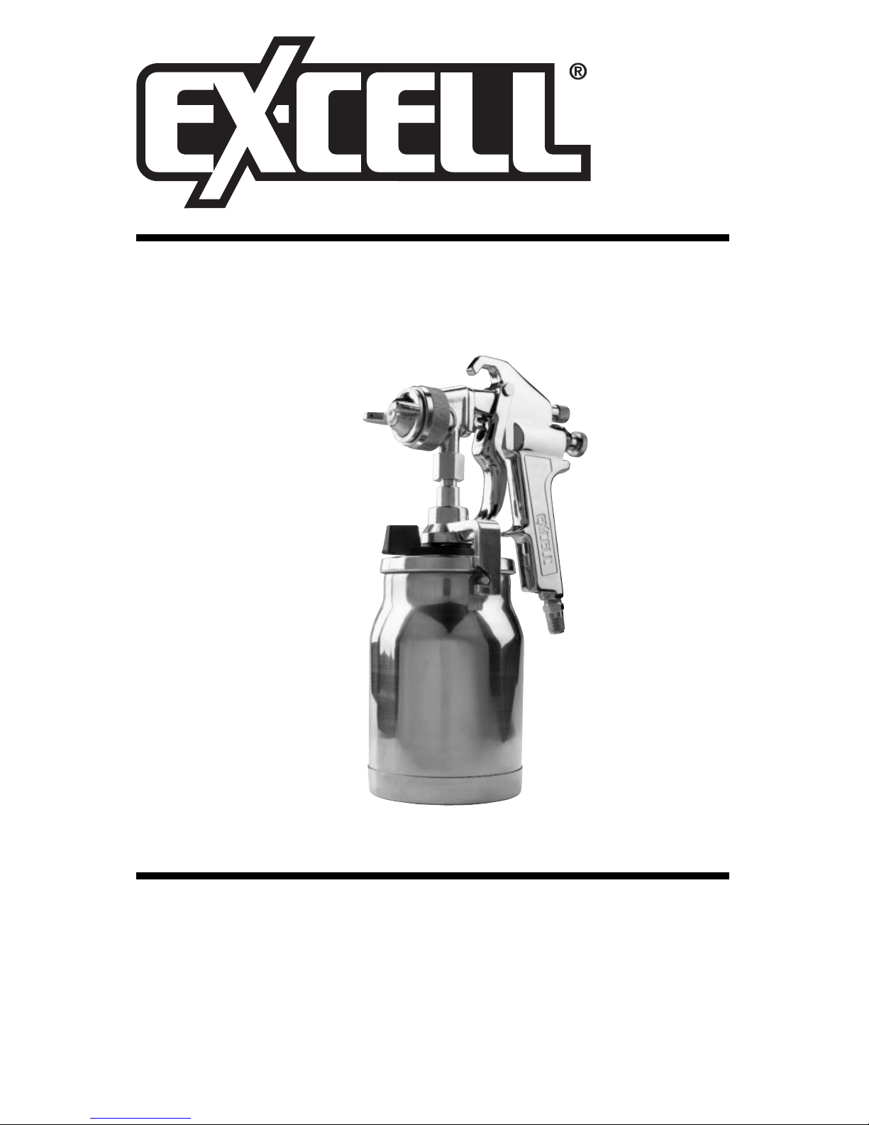
Suction Feed Spray Gun
Instruction manual
for model ES3-1
Part No. D28270 Rev. 0 12/30/02
2- ENG
D28270
• SAVE THESE INSTRUCTIONS •
IMPROPER OPERATION OR MAINTENANCE OF THIS
PRODUCT COULD RESULT IN SERIOUS INJURY AND
PROPERTY DAMAGE. READ AND UNDERSTAND ALL
WARNINGS AND OPERATING INSTRUCTIONS BEFORE
USING THIS EQUIPMENT.
The Following Hazards Can Occur During The Normal Use Of This Product:
HAZARD
WHAT CAN HAPPEN
HOW TO PREVENT IT
When paints or materials are
sprayed, they are broken into
very small particles and mixed
with air. This will cause certain
paints and materials to become
extremely flammable and could
result in serious injury or death.
Never spray near open flames
or pilot lights in stoves or
heaters.
Never smoke while spraying.
Provide ample ventilation when
spraying indoors.
RISK OF
EXPLOSION OR
FIRE -
FLAMMABLE
MATERIALS
SAFETY GUIDELINES - DEFINITIONS
Indicates an
imminently hazardous
situation which, if not avoided, will
result in death or serious injury
.
Indicates a potentially
hazardous situation
which, if not avoided, could
result in
death or serious injury
.
Indicates a potentially
hazardous situation
which, if not avoided, may
result in
minor or moderate injury.
Used without the
safety alert symbol
indicates a potentially hazardous
situation which, if not avoided, may
result in pr
operty damage.
SAFETY and PREVENTING EQUIPMENT PROBLEMS. To help you recognize this information, we
use the symbols below. Please read the manual and pay attention to these sections.
This manual contains information that is important for you to know and understand. This information
relates to protecting YOUR SAFETY and PREVENTING EQUIPMENT PROBLEMS. To help you
recognize this information, we use the symbols below. Please read the manual and pay attention to
these sections.
IMPORTANT SAFETY INSTRUCTIONS

3- ENG
D28270
RISK OF
EXPLOSION -
INCOMPATIBLE
MATERIALS
HAZARD
WHAT CAN HAPPEN
HOW TO PREVENT IT
SPECIFICATIONS
The solvents 1,1,1-Trichloroethane
and Methylene Chloride can
chemically react with the aluminum used in most spray equipment, and this gun and cup, to
produce an explosion hazard and
could result in serious injury or
death.
Read the label or data sheet for
the material you intend to spray.
1. Never use any type of
spray coating material
containing these solvents.
2. Never use these solvents
for equipment cleaning or
flushing.
3. If in doubt as to whether a
material is compatible,
contact your material
supplier.
Some paints, coatings and
solvents may cause lung damage,
and burns if inhaled or allowed to
come into contact with skin or
eyes.
Use a NIOSH approved mask
or respirator and protective
clothing designed for use with
your specific application and
spray materials. Some masks
provide only limited protection
against toxic materials and
harmful paint solvent. Consult
with a Safety Expert or Industrial Hygienist if uncertain about
your equipment or materials.
RISK TO
BREATHING
RISK FROM
FLYING OBJECTS
Certain parts are under pressure
whenever the gun is connected to
a pressurized air line. These parts
may be propelled if the gun is disassembled.
Compressed air may propel dirt,
metal shavings, etc. and possibly
cause an injury.
Prolonged exposure to air spray
can result in permanent damage
to hearing.
Disconnect the gun from the air
line, or completely depressurize
the air line whenever the gun is
to be disassembled.
Never point any nozzle or
sprayer toward a person or part
of the body.
Always wear ANSI 278.1 safety
approved goggles or glasses
when spraying.
Always wear hearing protection
when operating spray equipment.
Air Inlet 1/4 NPT
Maximum Air Pressure 100 psi.
Recommended Operating Air Pressure Range 60 psi.
Air Consumption @ 60 psi. 12.2 scfm (100% usage)
Cup Capacity 34 oz. (1005.5 cc)
Nozzle Size 1.8 mm
The cup provided with this gun is designed for siphon feed only, it is ideal for
applying light and medium bodied paints (stain, lacquer) to large size jobs such
as complete auto refinishing. For spraying on larger painting applications the
gun can be used with a remote pressure feed paint tank.
IMPORTANT: This gun is designed to be use with most finishing materials. It is
not designed to be used with corrosive or highly abrasive materials. Using these
materials can lead to poor performance and/or failure of this product.
Before use
●
Install a moisture
separator/regulator when there
is a possibility moisture will
damage the surface to be
painted. Install the moisture
separator/regulator as close to
the tool as possible.
NOTE: Liquid water occurs
naturally in air lines as a result
of compression. The moisture
exiting near the compressor is
warm and still in a vapor state which allows it to pass through the moisture
separator. The vapor must travel a minimum of 5 to 10 feet to cool down to
a liquid to be removed by the moisture separator. See Illustration.
●
Prior to shipment, this gun was treated with an anticorrosive agent. Before
using this gun make sure that it is carefully flushed with thinner.
4- ENG
D28270
Before disassembly or removal of any part of gun or
attached components, shut off compressor, release
pressure by depressing trigger, and disconnect power source. NEVER
assume system pressure is zero!
TO AVOID CREATING AN EXPLOSIVE ATMOSPHERE,
WORK ONLY IN WELL-VENTILATED AREAS.
USE OF A NIOSH APPROVED FACE MASK IS
RECOMMENDED TO PREVENT INHALATION OF TOXIC
MATERIAL.
DO NOT ATTEMPT TO UNCLOG (BACK FLUSH) SPRAY
GUN BY SQUEEZING TRIGGER WHILE HOLDING
FINGER IN FRONT OF FLUID NOZZLE.
Pressure may vary according to viscosity of material
used. Maximum working pressure of gun is 100 psi. DO
NOT EXCEED PRESSURE LIMIT OF GUN OR ANY OTHER COMPONENT IN SYSTEM!
Prior to daily operation, make certain that all
connections and fittings are secure. Check hose and all
connections for a weak or worn condition that could render system
unsafe. All replacement components such as hose or fittings must have
a working pressure equal to or greater than system pressure.
GENERAL INFORMATION
OPERATION

TO USE
1. Mix material according the
manufacturer’s instructions. Mixture
should be smooth and easily pourable.
Lumps or foreign particles should be
removed by straining through a
suitable paint filter.
NOTE: If not using the siphon feed setting,
see “Remote Pressure Feed” paragraphs.
2. Remove the material cup (e) from
lid/gun assembly. NOTE: Slide release
lever (f) to the right, rotate lid, and
remove material cup (e).
3. Fill the material cup (e) 3/4 full.
4. Attach material cup (e) to the lid/gun
assembly and slide release lever (f) to
the left to secure in place.
5. Attach air supply line to 1/4 NPT air
inlet (c).
6. Adjust spray pattern.
a. The position of the air cap horns (g) will
determine the spray pattern. Loosen air
cap (h) and rotate horns to achieve
desired pattern. Tighten air cap.
7. Turn fluid control knob (b) clockwise until it
stops, do not force. This will shut off the fluid flow. NOTE: The fluid or density of “fan spray” is controlled by fluid control knob (b).
8. Adjust air pressure to 60 psi at air compressor.
DO NOT exceed 100 psi.
9. Turn air valve control knob (a)
counterclockwise until first thread is flush with
gun body. NOTE: Air flow is controlled by air
valve control knob (a).
DO NOT turn air valve
control knob or fluid control
knob out until the first thread is past the gun
body. They are under pressure when the gun
is triggered and could leave the gun with
force.
NOTE: Care should be exercised when handling spray gun to avoid damage to
the orifice of the air cap and tip of fluid nozzle. Damage to these parts results in
irregular spray patterns.
9. Depress spray gun trigger (d) and gradually turn the fluid control knob (b)
counterclockwise until desired fluid flow is reached. Trigger gun quickly, one
second on-off to test pattern.
NEVER point spray gun at self or any other person.
Accidental discharge of material may result in serious
injury.
NOTE: If gun sprays too fast, decrease the air and fluid pressure. If too slow,
increase the pressure. Turn fluid control knob (b) counterclockwise to increase,
or clockwise to decrease, the fluid flow. Turn air valve control knob (a) counterclockwise to increase, or clockwise to decrease, the air flow.
5- ENG
D28270
e
f
a
b
g
c
d
h
Horizontal position
Vertical position
a
b
first thread flush

6- ENG
D28270
Spraying Tips
1. The stroke is made with a free arm motion, keeping the gun at a right angle
to the surface at all points of the stroke. Arching the stroke will result in
uneven application and excessive over spray at each end of the stroke.
2. Depress trigger just before reaching the edge of the surface to be sprayed.
Hold the trigger fully depressed and move the gun in one continuous
motion. Release the trigger when the other edge of the surface is reached,
shutting off the fluid flow, but continue motion a few inches until it is
reversed for the return stroke. When the edge of the surface is reached on
the return stroke, depress the trigger fully again and continue across the
surface.
3. Lap each stroke 50% over the preceding one. Less than 50% will cause
streaks on the finish surface.
Convert to Remote Pressure Feed:
If the material to be sprayed is too heavy for siphon feed or fast application is
desired, convert to the pressure feed setting.
1. Remove the material cup (e) from lid/gun assembly. NOTE: Slide release
lever (f) to the right, rotate lid, and
remove material cup (e).
2. Slide yoke (g),with built in socket
feature, over nut (h). Grip the yoke
and turn to loosen nut, after the nut
is loosened hand turn until lid
assembly can be removed from gun.
3. The gun is now ready to be
connected to any pressure feed tank
with a standard 3/8" straight pipe
female connection. See
manufacturer’s manual for correct
procedure.
4. To operate see steps 5-9 in the “To Use” section to continue.
NEVER point spray gun at self or any other person. Ac-
cidental discharge of material may result in serious
injury.
NOTE: When replacing lid assembly to gun assembly hand tighten nut (h) and
then slide yoke (g) over nut (h) to tighten securely.
g
h

7- ENG
D28270
Always exercise extreme care when using any solvent
or thinner. Never clean gun near fire, flame, or any
source of heat or sparks. Properly dispose of used cleaning materials.
DO NOT soak entire spray gun in solvent or thinner for
a long period of time as this will destroy lubricants and
possibly make motion uneven. NEVER use lye or caustic alkaline solution for cleaning. Such solutions will attack aluminum alloy parts of
gun.
It is important that spray gun be cleaned after daily use. Cleaning is accomplished by spraying appropriate solvent or thinner through system.
Cleaning
NOTE: Clean gun immediately after use. Paint and other materials dry
quickly in the small passages.
1. Turn off air supply to gun.
2. Remove the material cup (e) from lid/gun assembly. NOTE: Slide release
lever (f) to the right, rotate lid, and remove material cup (e).
When using the remote pressure feed method: See manufacturer’s
manual for suggested cleaning of remote cup or tank.
3. Empty material from material cup and replace with a suitable solvent. If
using water based material use mineral spirits to prevent corrosion.
4. Turn air supply on and operate trigger until all material traces have disappeared and gun is thoroughly clean.
NOTE: To remove lid assembly from gun assembly, slide yoke (g),with built in
socket feature, over nut (h). Grip the yoke and turn to loosen nut, after the nut is
loosened hand turn until lid assembly can be removed from gun. When replacing
lid assembly to gun assembly, hand tighten nut (h) and then slide yoke (g) over
nut (h) to tighten securely.
IMPORTANT: Do not immerse the gun in solvent, this will cause damage to
the packings.
NOTE: Always comply with local codes when disposing of solvents.
5. Remove air cap and immerse in a suitable solvent. Use a bristle brush to
clean dried paint and blow it dry with compressed air.
6. Use cleaning tool (supplied) to clean small clogged holes.
7. Wipe gun with a solvent soaked cloth.
IMPORTANT: Make certain air cap and fluid nozzle are kept clean at all
times. DO NOT use hard objects to clean clogged holes. The smallest
amount of damage may cause irregular spray pattern.
Lubrication
Lubrication procedures must be observed after thoroughly cleaning the gun to
ensure effective, high quality performance of spray gun.
1. Lubricate working points with straight mineral oil, or castor oil.
2. Periodically, place a few drops of oil on tapered sections of fluid nozzle to
ensure easy operation of air cap. When spraying water base materials, coat
fluid nozzle inside and outside with straight mineral oil after each use.
MAINTENANCE
8- ENG
D28270
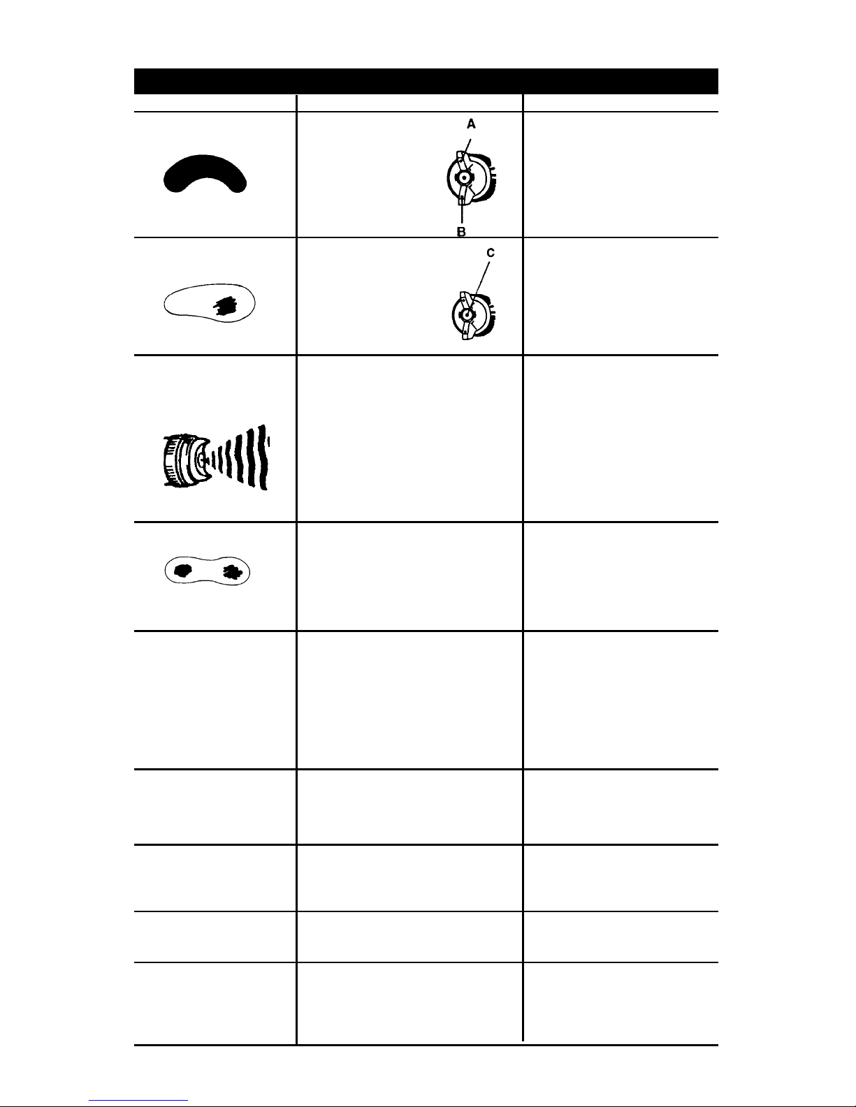
Dried material
is clogging
side-port “A”
and causing
side-port “B” to
blow spray
towards the
clogged side
A.
Soak side-ports in
thinner to clean clog.
DO NOT poke any
opening with hard
objects.
B.
Dried material at
fluid nozzle “C”
restricts air flow
Loose air nozzle
Air pressure set
too high
Remove air nozzle.
Wipe off fluid tip using a
cloth soaked in thinner
or by soft brush
Fasten nozzle securely
Reduce air pressure
C. Spitting, irregular
or fluttering spray
Fluid nozzle cracked or worn
Leak at thread of fluid nozzle
Leak at fluid needle
Needle packing worn out
Insufficient fluid in cup
Vent hole in container cover
clogged
Tighten or replace
Tighten fluid nozzle
Tighten compression nut
assembly or replace
needle packing
Replace packing
Fill cup with fluid
Clean Out
D. Split spray pattern
Air pressure too high
Turn pattern control
knob clockwise to
decrease fan width.
Turn fluid needle
adjusting nut counterclockwise to increase
fluid flow
Material too heavy
Insufficient air pressure
Fluid pressure too high
Dried material on tip of fluid
nozzle or air jets of air cap
Thin material or use
larger orifice fluid nozzle
set
Increase pressure to
within limit
Reduce pressure
Clean
Air needle partially closed
Dried material in air jets or air
cap
Obstruction in air line
Remove obstruction
Reduce air pressure
and/or open fluid control
knob
Air pressure to high for
viscosity of fluid
Loose cup or foreign substances on/between cup
thread and fluid inlet
Tighten and clean or
replace it
F. Inadequate air de-
livery
E. Unatomized or
spattered spray
G. Excessive fog
I. Material leaking
from nozzle when
trigger is released
H. Material leaking
from fluid inlet of
cup.
Worn fluid needle
Dried material in tip of nozzle
Loose packing nut
Replace
Clean
Tighten needle packing
nut by turning
counterclockwise
Defective Pattern
Likely Cause Suggested Remedy
TROUBLESHOOTING
Open control knob
Clean
9- ENG
D28270
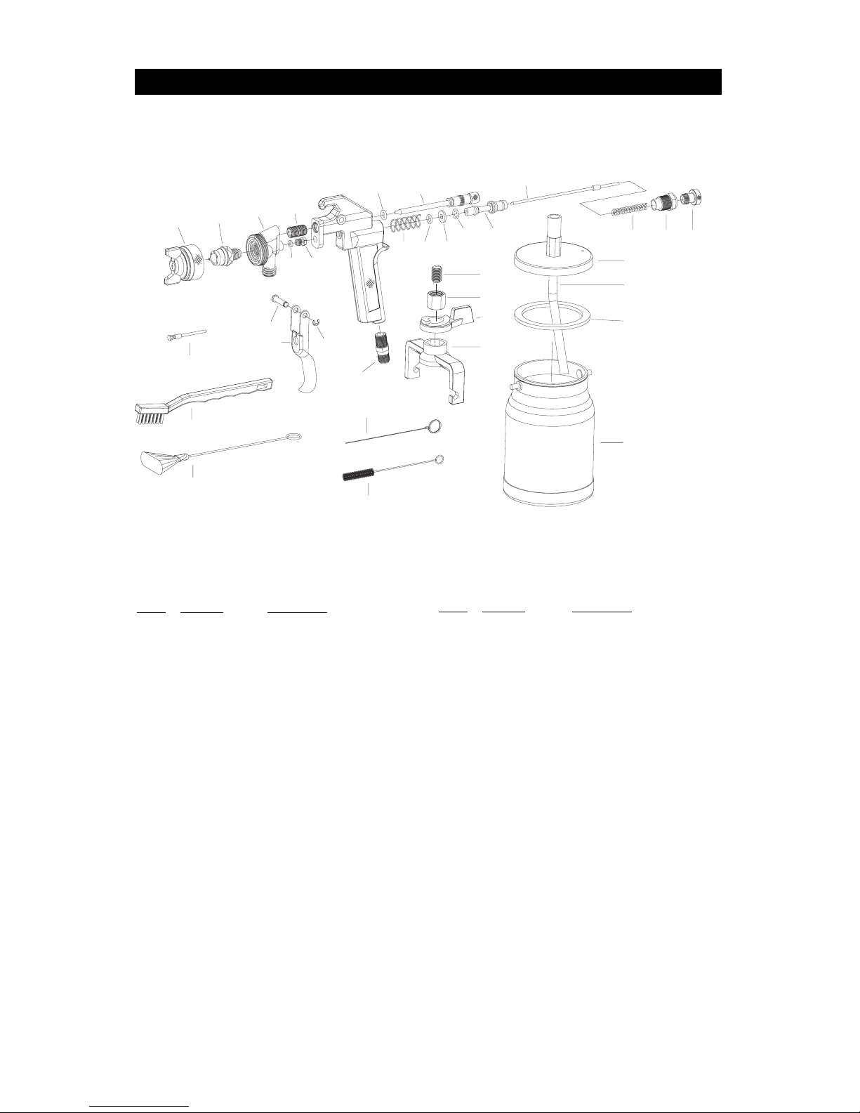
PARTS LIST
1
2
3
4
6
5
17
16
15
14
13
12
7
9
25
22
23
10
8
18
24
26
29
30
28
11
19
20
21
27
31
33
32
34
Key # Part No. Description
1 D26508 Air Nozzle w/brass cap
2 D26509 Fluid Nozzle
3 D26510 Head
4 D26511 Screw
5 D26512 Air Valve Assembly
6 * O-Ring
7 * Packing Nut
8 D26461 Trigger
9 * Cow Hide Washer
10 D26462 Screw
11 D25172 E-Ring
12 D26463 Air Valve Spring
13 * O-Ring
14 * O-Ring
15 * O-Ring
16 D26464 Valve Stem assembly
17 D26518 Fluid Needle Assembly
Key #
Part No. Description
18 D26519 Air Connection
19 D26467 Spring
20 D26468 Retaining Nut
21 D26469 Fluid Needle Adjusting Screw
22 D26480 Plastic Grip Brush
23 D26481 Witch Brush
24 D26503 Needle
25 D26479 Copper Grip Brush
26 D26483 Brush
27 D26520 Screw
28 D26521 Nut
29 D26522 Arm
30 D26523 Lever Release
31 D26524 Lid Canister
32 * Gasket
33 D26526 Siphon Tube
34 D26527 Canister
* Only available in Seal Kit part number D23933

10- ENG
D28270
LIMITED WARRANTY
All merchandise manufactured by DAPC is warranted to be free of defects in workmanship and
material which occur during the first year from the date of purchase by the original purchaser (initial
user). Products covered under this warranty include: air compressors, *air tools, accessories, service
parts, pressure washers, and generators used in consumer applications (i.e., personal residential
household usage only).
Air compressors, *air tools, accessories, service parts, pressure washers, and generators used in
commercial applications (income producing) are covered by a 90 day warranty.
DAPC will repair or replace, at DAPC’s option, products or components which have failed within the
warranty period. Repair or replacement, and service calls on 60 and 80 gallon air compressors, will be
handled by Authorized Warranty Service Centers and will be scheduled and serviced according to the
normal work flow and business hours at the service center location, and depending on the availability
of replacement parts.
All decisions of DAPC with regard to this policy shall be final.
This warranty gives you specific legal rights, and you may also have other rights which vary from state
to state.
RESPONSIBILITY OF ORIGINAL PURCHASER (Initial User):
To process a warranty claim on this product, DO NOT return it to the retailer. The product must be
evaluated by an Authorized Warranty Service Center. For the location of the nearest Authorized
Warranty Service Center call 1-800-888-2468, 24 hours a day, 7 days a week or visit our web site
at www.devap.com.
Retain original cash register sales receipt as proof of purchase for warranty work.
Use reasonable care in the operation and maintenance of the product as described in the Owners
Manual(s).
Deliver or ship the product to the nearest DAPC Authorized Warranty Service Center. Freight
costs, if any, must be paid by the purchaser.
Air compressors with 60 and 80 gallon tanks only will be inspected at the site of installation.
Contact the nearest Authorized Warranty Service Center, that provides on-site service calls, for
service call arrangement.
If the purchaser does not receive satisfactory results from the Authorized Warranty Service
Center, the purchaser should contact DAPC.
THIS WARRANTY DOES NOT COVER:
Merchandise sold as reconditioned, floor models and/or display models. Any damaged or
incomplete equipment sold "as is".
Merchandise used as "rental" equipment.
Merchandise that has become inoperative because of ordinary wear, misuse, freeze damage, use
of improper chemicals, negligence, accident, improper and/or unauthorized repair or alterations
including failure to operate the product in accordance with the instructions provided in the
Owners Manual (s) supplied with the product.
*Air Tools: O-Rings and driver blades are considered ordinary wear parts, therefore, they are
warranted for a period of 45 days from the date of purchase.
An air compressor that pumps air more than 50% during a one hour period is considered misuse
because the air compressor is undersized for the required air demand. Maximum compressor
pumping time per hour is 30 minutes.
Merchandise sold by DAPC which has been manufactured by and identified as the product of
another company. The product manufacturer's warranty will apply.
Repair and transportation costs of merchandise determined not to be defective.
Cost associated with assembly, required oil, adjustments or other installation and start-up cost.
Any incidental, indirect or consequential loss, damage, or expense that may result from ANY
defect, failure or malfunction of the product. Some states do not allow the exclusion or limitation
of incidental or consequential damages, so the above limitation or exclusion may not apply to
you.
Implied warranties, including those of merchantability and fitness for a particular PURPOSE, are
limited to one year from the date of original purchase. Some states do not allow limitations on
how long an implied warranty lasts, so the above limitations may not apply to you.
DAPC
213 Industrial Drive • Jackson, TN 38301-9615
Telephone: 1-800-888-2468
FAX: 1-800-888-9036

IMPORTANTE
Sírvase asegurarse que la persona que utilizará este equipo lea
cuidadosamente y comprenda estas instrucciones, antes de
comenzar a operarlo.
Pistola rociadora alimentada por succión
Manual de instrucciones
Para el modelo ES3-1
Pieza N° D28270 Rev. 0 12/30/02

12- SP
D28270
• CONSERVE ESTAS INSTRUCCIONES •
LA OPERACIÓN O EL MANTENIMIENTO INADECUADOS DE
ESTE PRODUCTO PODRÍAN DETERMINAR SERIAS LESIONES
Y DAÑOS A LA PROPIEDAD. LEA Y COMPRENDA TODAS LAS
ADVERTENCIAS E INSTRUCCIONES OPERATIVAS ANTES DE
UTILIZAR ESTE EQUIPO.
Pueden ocurrir las siguientes situaciones de peligro durante el uso normal
de este producto:
PELIGRO
QUÉ PUEDE OCURRIR
CÓMO PREVENIRLO
Cuando se rocía con pinturas o
materiales, ellas se fraccionan en
pequeñas partículas que se
mezclan con el aire. Ello origina
que ciertas pinturas y materiales
se tornen extremadamente
inflamables y puedan causar
serias lesiones o la muerte.
Jamá rocíe en las cercanías de
llama abierta o llamas piloto en
cocinas o calefactores.
Jamás fume mientras esté
rociando.
Al rociar en interiores,
suministre amplia ventilación.
RIESGO DE
EXPLOSIÓN O
INCENDIO -
MATERIALES
INFLAMABLES
NORMAS DE SEGURIDAD - DEFINICIONES
Indica una situación de
peligro inminente que,
si no es evitada, podrá causar
la muerte o serias lesiones
.
Indica una
situación potencialmente riesgosa que, si
no es evitada, podría
ocasionar la muerte
o lesiones serias.
Indica una situación
potencial de riesgo,
que, si no es evitada, puede
causar
lesiones menores o moderadas.
Utilizada sin el símbolo
de alerta de seguridad,
indica una situación potencialmente
riesgosa que, si no es evitada, puede
ocasionar daños a la pr
opiedad.
SEGURIDAD y PREVENCIÓN DE PROBLEMAS AL EQUIPO. Para ayudarlo a identificar esta información
hemos utilizado los símbolos que se indican más abajo. Sírvase leer el manual y prestar atención a dichas
secciones.
Este manual contiene información que resulta importante para que usted conozca y comprenda. Esta
información se relaciona con la protección de SU SEGURIDAD y LA PREVENCIÓN DE
PROBLEMAS A SU EQUIPO. Para ayudarlo a identificar esta información hemos utilizado los
símbolos que se indican más abajo. Sírvase leer el manual y prestar atención a dichas secciones.
IMPORTANTES INSTRUCCIONES DE SEGURIDAD

13- SP
D28270
ESPECIFICACIONES
Entrada de aire 1/4 NPT
Máxima presión de aire 100 psi.
Recomendado para operar el aire a presión 60 psi.
Capacidad del pote 1005.5 cm
3
(34 onzas)
Consumo de aire a 60 psi. 12.2 scfm (100% de uso)
Diámetro de la boquilla 1.8 mm
RIESGO DE
EXPLOSIÓN -
MATERIALES
INCOMPATIBLES
PELIGRO
QUÉ PUEDE OCURRIR
CÓMO PREVENIRLO
Solventes del tipo 1, 1, 1 Tricloroetano y Cloruro de
metileno, pueden reaccionar
químicamente con el aluminio
utilizado en la mayoría de los
equipos de rociado, esta pistola y
su copa, produciendo una
explosión que podría determinar
serias lesiones o la muerte.
Lea la etiqueta o la hoja de
especificaciones del material
que usted intenta rociar.
1.Jamás use tipo alguno de
material que contenga esos
solventes.
2.Jamás use esos solventes
para la limpieza del equipo o su
enjuagado.
3.En caso de dudas respecto a
la compatibilidad del material,
contacte a su proveedor de
materiales.
Algunas pinturas, recubrimientos y
solventes pueden causar daños
pulmonares y quemaduras, si son
inhalados o permitidos que tomen
contacto con la piel o los ojos.
Utilice una máscara aprobada
NIOSH o un respirador y ropa
protectora diseñada para ser usada
con su aplicación específica y
materiales de rociado. Algunas
máscaras solo proveen una
protección limitada contra
materiales tóxicos y solventes
dañinos de pinturas. En caso de
incertidumbre acerca de su equipo
o materiales, consulte con un
experto en seguridad o un
higienista industrial.
RIESGO DE
INHALACIÓN
RIESGO DE
OBJETOS
ARROJADOS
Ciertas partes se encuentran
sometidas a presión, cuando la
pistola está conectada a una
tubería de aire comprimido. Esas
partes podrían ser expulsadas si la
pistola fuese desarmada.
El aire comprimido puede arrojar
suciedad, partículas de metal, etc
y posiblemente ocasionar
lesiones.
La exposición prolongada al
rociado de aire puede ocasionar
daños permanentes de audición.
Desconecte la pistola de la
cañería de aire, o despresurice
completamente la misma, cada
vez que la pistola deba ser
desarmada.
Jamás apunte ninguna boquilla
o rociador hacia persona alguna
o parte del cuerpo.
Al rociar, use siempre antiparras
de seguridad ANSI 278.1
aprobadas.
Al operar equipo de rociado,
use siempre protección
auditiva.

14- SP
D28270
La copa provista con esta pistola está diseñada para alimentación a sifón únicamente; resulta ideal
para la aplicación de pinturas livianas y medianas para carrocerías (tinturas, lacas) para trabajos
grandes tales como la pintura completa de terminación de un auto. Para el atomizado en aplicaciones
extensas, la pistola puede ser utilizada con un tanque de pintura de alimentación remota.
IMPORTANTE: Esta pistola está diseñada para ser utilizada con la mayoría de los materiales para
terminación. No está diseñada para ser usada con materiales corrosivos o altamente abrasivos. El uso
de dichos materiales puede conducir a una pobre performance y/o la falla de este producto.
Antes del desarmado o remoción de cualquier parte, del
pistola o cualquiera de sus componentes, apague el compresor,
libere su presión apretando el gatillo, y desconecte el suministro de corriente eléctrica.
¡JAMÁS asuma que la presión del sistema es cero
!
PARA EVITAR LA CREACIÓN DE UN ATMÓSFERA
EXPLOSIVA, TRABAJE SOLAMENTE EN ÁREAS BIEN
VENTILADAS.
SE RECOMIENDA EL USO DE UNA MÁSCARA FACIAL
NOISH PARA PREVENIR LA INHALACIÓN DE
MATERIALES TÓXICOS.
INFORMACIÓN GENERAL
OPERACIÓN
NO INTENTE DESTRABAR (POR FLUJO INVERTIDO) LA
PISTOLA ROCIADORA, PRESIONANDO EL GATILLO
COLOCANDO SU DEDO FRENTE AL PICO ROCIADOR DE FLUIDO.
La presión puede variar de acuerdo a la viscosidad del material
utilizado. La máxima presión de trabajo de la pistola es de 100
PSI. ¡NO EXCEDA EL L
Í
MITE DE PRESI
ÓN DE LA PISTOLA NI DE CUALQUIER OTRO
COMPONENTE DEL SISTEMA
!
Antes de la operación diaria, asegúrese de que todas las
conexiones y conectores estén seguros. Verifique la condición de
desgaste y debilitamiento de la manguera y todas las conexiones que pudiesen crear un
sistema inseguro. Todos los componentes de reemplazo, tales como mangueras o
conectores, deberán tener una presión de trabajo igual o mayor que la presión del
sistema.
Antes de usar:
●
Instale un separador / regulador de
humedad donde exista la posibilidad de
humedad que pudiese dañar la
superficie que debe ser pintada. Instale
el separador / regulador de humedad
lo más cercano posible a la
herramienta.
●
NOTA: El agua en estado liquido
ocurre naturalmente en cañerías de aire
como resultado de la compresión. La
humedad que sale cercana al
compresor es cálida y aun en estado de
vapor que le permite pasar a través del separador de humedad. El vapor debe viajar a través
de un mínimo de 1,50 m a 3 m, con el objeto de enfriarse hasta su estado líquido, y poder ser
extraído por el separador de humedad. Ver ilustración.
●
Antes de su despacho, esta pistola ha sido tratada con un agente anticorrosivo. Antes de usarla
asegúrese de que la pistola ha sido cuidadosamente enjuagada con solvente.

15- SP
D28270
CÓMO USAR:
1. Mezcle el material de acuerdo a las
instrucciones del fabricante. La mezcla debe ser
ligera y fácilmente fluida. Grumos o partículas
extrañas deberán extraerse a través de un filtro
adecuado para pintura.
NOTA: Si no se utilizan las características de
alimentación por sifón, vea los párrafos de
"Alimentación remota a presión".
2. Extraiga la copa del material (e) del conjunto
tapa / pistola. NOTA: Deslice la palanca de
liberación (f) hacia la derecha, gire la tapa y
extraiga la copa de material (e).
3. Llene la copa de material (e) hasta 3/4 de su
capacidad.
4. Conecte la copa de material (e) al conjunto
tapa / pistola y deslice la palanca de liberación (f)
hacia la izquierda para asegurarla en su sitio.
5. Conecte el suministro de aire a un conector
para aire (c) de 1/4 NPT.
6. Regule el patrón de rociado
a) La posición de los extremos córneos (g) de la
válvula de aire determinarán el patrón de rociado.
Afloje la válvula de aire (h) y rote los extremos
córneos a fin de lograr el patrón deseado. Ajuste la
válvula de aire.
7. Gire la perilla de control de fluido (b)
en sentido horario hasta su limite, no la
fuerce. Ello cerrará el paso del fluido.
NOTA: el fluido o densidad del "sopleteo de rociado" queda controlado por
la perilla de control de fluido (b).
8. Regule la presión del aire en el compresor a 60 PSI
NO exceda los 100 PSI.
9. Gire la perilla de control de la válvula de aire (a) en
sentido antihorario hasta su que el primer filete de
rosca esté a ras con el cuerpo de la pistola. NOTA:
El flujo del aire está controlado por la perilla de
control de la válvula de aire (a).
NO extraiga la perilla de
control del fluido hasta que el
primer filamento haya penetrado el cuerpo de la
pistola. El mismo queda bajo presión cuando se
presiona el gatillo de la pistola y podría salirse de
la pistola violentamente.
NOTA: Debe tenerse cuidado al manipular la pistola rociadora, a fin de evitar daño al
orificio de la válvula de aire y a la punta del pico de fluido. El daño a dichas partes
resultará en patrones irregulares de rociado.
10. Presione el gatillo (d) de la pistola rociadora y gradualmente abra la perilla de
control de fluido (b) girándola en sentido antihorario hasta lograr el flujo de fluido
deseado. Presione repetitivamente el gatillo para verificar el patrón de rociado.
JAMÁS apunte la pistola rociadora a sí mismo o a persona
alguna. Una descarga accidental de material podría
determinar serias lesiones.
Posición horizontal
Posición vertical
a
b
e
f
a
b
g
c
d
h
Primer filete a ras

16- SP
D28270
Sugerencias para pulverizado
1. El trazo debe ser efectuado a brazo libre, manteniendo la pistola en ángulo recto a la
superficie durante todos los puntos del trazo. Si se realizan los trazos en forma de
arco ello resultará en una aplicación despareja y un excesivo pulverizado en cada
extremo del trazo.
2. Presione el gatillo inmediatamente antes de llegar al borde de la superficie que debe
ser pulverizada. Sostenga el gatillo completamente oprimido y mantenga la pistola
en un movimiento continuo. Suelte el gatillo al llegar al otro borde, interrumpiendo el
paso del fluido, pero continuando con el movimiento unos pocos centímetros hasta
que el movimiento sea invertido para el siguiente trazo. Cuando se llegue al borde de
la superficie en el trazo de retorno, presione completamente el gatillo nuevamente y
continúe a través de la superficie.
3. Sobreponga cada trazo 50% sobre el precedente. Menos que el 50% causara rayas
sobre el acabado superficial.
NOTA: Si la pistola pulveriza demasiado rápido, desminuya la presión de salida del aire y del
fluido. Si es demasiado baja, incremente la presión. Gire la perilla de control de fluido (b)
en sentido antihorario para incrementar, o en sentido horario para disminuir la salida del aire.
Gire la válvula de control del aire (a) en sentido antihorario para incrementar, o en sentido
horario para disminuir el flujo de aire.
Conversión a alimentación remota a presión:
Si el material que debe ser rociado es demasiado denso para la alimentación por sifonado
o si desea efectuar una aplicación rápida, convierta a la modalidad de alimentación a
presión.
1. Extraiga la copa del material (e) del conjunto tapa / pistola. NOTA: Deslice la palanca
de liberación (f) hacia la derecha, gire la tapa y extraiga la copa de material (e).
2. Deslice la brida (g), con el zócalo incorporado, sobre la tuerca (h). Sujete la brida y
gírela para aflojar la tuerca, luego que la
tuerca esté floja gírela a mano hasta que
el conjunto de la tapa pueda ser extraído
de la pistola.
3. La pistola está lista ahora para ser
conectada a cualquier tanque de
alimentación a presión que tenga una
conexión estándar hembra recta de 3/8".
Vea el manual del fabricante para
referirse al procedimiento correcto.
4. Para operar, vea los pasos 5 al 9 en la
sección "Cómo usar" para poder
continuar.
JAMÁS apunte la
pistola rociadora a sí mismo o contra cualquier otra
persona. Una descarga accidental de material podría determinar serias lesiones.
NOTA: Al reponer el conjunto de la tapa al conjunto de la pistola ajuste la tuerca (h) a
mano, luego deslice la brida (g) sobre la tuerca (h) para ajustar firmemente.
g
h

17- SP
D28270
MANTENIMIENTO
Ejerza siempre extremo cuidado al utilizar cualquier solvente
o diluyente. Jamás limpie la pistola cerca del fuego, llama o
cualquier fuente de calor o chispas. Deseche adecuadamente los materiales
utilizados para limpieza.
NO embeba la pistola rociadora completamente en solvente o
diluyente durante un largo periodo de tiempo, dado que ello
destruirá lubricantes y posiblemente torne desparejo su movimiento. JAMÁS use
lejía o soluciones alcalinas ácidas para la limpieza. Tales soluciones atacan el
aluminio de las aleaciones de partes de la pistola.
Es importante que la pistola rociadora sea limpiada después de cada uso. La limpieza se cumple
rociando con un solvente apropiado o diluyente a través del sistema.
Limpieza
NOTA: Limpie la pistola inmediatamente después de su uso. Pintura y otros materiales
secan rápidamente dentro de pasajes reducidos.
1. Interrumpa el suministro de aire a la pistola.
2. Extraiga la copa de material (e) del conjunto tapa / pistola. NOTA: Deslice la palanca
liberadora (f) hacia la derecha, gire la tapa y extraiga la copa del material (e).
Cuando utilice el método de presión para la alimentación remota: Vea el manual
del fabricante acerca de la forma sugerida para la limpieza de la copa o el tanque
remoto.
3. Vacíe el material de la copa y reemplácelo con un solvente adecuado. Si se usa material
basado en agua, utilice aguarrás mineral para prevenir la corrosión.
4. Conecte el suministro de aire y presione el gatillo hasta que hayan desaparecido todas las
trazas de material y la pistola haya quedado completamente limpia.
NOTA: Para extraer el conjunto de la tapa del conjunto de la pistola, deslice la brida (g),
con el zócalo, sobre la tuerca (h). Sujete la brida y gírela para aflojar la tuerca, luego que
la tuerca ha quedado floja, gire a mano hasta que el conjunto de tapa pueda ser extraído
de la pistola. Al reponer el conjunto de la tapa al conjunto de la pistola, ajuste la tuerca (h)
a mano y luego deslice la brida (g) sobre la tuerca (h) para ajustar firmemente.
IMPORTANTE: No sumerja la pistola en solvente, ello dañará las empaquetaduras.
NOTA: Cumpla siempre son las disposiciones locales al desechar solventes.
5. Extraiga la válvula de aire y sumérjala en un solvente apropiado. Utilice un cepillo de cerda
dura para limpiar la pintura seca y sopletéela en seco con el compresor de aire.
6. Utilice la herramienta de limpieza (provista) para limpiar pequeños orificios obturados.
7. Limpie la pistola con una tela embebida en solvente.
IMPORTANTE: Asegúrese de que la válvula de aire y el pico del fluido se mantengan
limpios en todo momento. NO utilice objetos duros para la limpieza de orificios
obturados. Un daño pequeño puede causar un patrón de rociado irregular.
Lubricación
Deben observarse los procedimientos de lubricación luego de una limpieza completa de
la pistola, con el fin de mantener la efectividad, y la performance de alta calidad de la
pistola pulverizadora.
1. Lubrique puntos de trabajo con aceite mineral puro o aceite castor.
2. Periódicamente coloque unas gotas de aceite a las secciones fresadas del pico de fluido a fin
de facilitar la operación de la válvula de aire. Al atomizar materiales con base acuosa, después
de cada uso, aplique una capa de aceite mineral puro sobre la parte interna y externa del pico
de fluido.

18- SP
D28270
Material seco que
esta obturando el
portal del lado "A",
siendo la causa de
que el portal "B"
atomice hacia el
lado obturado.
A.
Embeba en diluyente los
laterales de los portales
para limpiar la
obturación. NO
aguijonee abertura
alguna con objetos
duros.
B.
Material seco en el pico
"C" del fluido,
restringiendo el flujo del
aire.
Afloje el pico del aire; la
presión del aire está
calibrada demasiado alta.
Extraiga la válvula de aire.
Limpie el exceso de fluido
de la punta utilizando una
tela embebida en diluyente
o por medio de un cepillo
de cerda blanda.
Atornille firmemente el pico.
Reduzca la presión del aire.
C. Salpicadura,
atomizado irregular
u ondulado
Pico de fluido rajado o gastado.
Goteo en la rosca del pico de fluido.
Goteo en la aguja del fluido.
La empaquetadura de la aguja se
ha gastado.
Insuficiente fluido en la copa.
El orificio de ventilación de la
cubierta del contenedor está
obturado.
Ajuste o reemplace.
Ajuste el pico del fluido.
Ajuste la tuerca del conjunto
de compresión o reemplace la
empaquetadura de la aguja.
Reemplace la
empaquetadura.
Llene la copa con fluido.
Limpie.
D. Patrón separado de
atomizado
Presión de aire demasiado
elevada.
Gire en sentido horario la
perilla de control del patrón
de rociado para disminuir el
ancho de pulverizado.
Gire en sentido antihorario la
tuerca de ajuste de la aguja
del fluido para incrementar el
flujo del mismo.
Material demasiado pesado
Presión de aire insuficiente
Presión de fluido demasiado
elevada.
Material seco en la punta del
pico de fluido, o escapes en
los conductos de la válvula
de aire.
Diluya el material o
utilice un orificio mayor
en la selección del pico.
Incremente la presión
dentro de los limites
permitidos.
Reduzca la presión.
Limpie.
Aguja del aire parcialmente cerrada.
Material seco en los conductos de la
válvula de aire.
Obstrucción de la cañería de aire.
Reduzca la presión del aire
y/o abra el paso del fluido
con la perilla de control.
Presión de aire demasiado
elevada para la viscosidad del
fluido.
Copa floja o substancias extrañas
en/entre los filetes de rosca de la
copa y la entrada del fluido.
Ajuste y limpie o
reemplace.
F. Entrega
inadecuada de aire
E. Rociado sin
atomizar o
punteado
G. Niebla Excesiva
I. Goteo de material
en el pico cuando
se suelta el gatillo
H. Goteo de material
en la conexión del
fluido de la copa.
Aguja de fluido gastada.
Material seco en la punta del pico.
Tuerca floja de empaquetadura.
Reemplace.
Limpie.
Ajuste la tuerca de la
empaquetadura de la aguja
girándola en sentido antihorario.
Patrón defectuoso Causa probable
Solución sugerida
DIAGNÓSTICO DE PROBLEMAS
Abra la perilla de control.
Limpie.
Remueva la obstrucción.

19- SP
D28270
LISTA DE PIEZAS
1
2
3
4
6
5
17
16
15
14
13
12
7
9
25
22
23
10
8
18
24
26
29
30
28
11
19
20
21
27
31
33
32
34
N° Clave Pieza N° Descripción
1 D26508
Pico para aire con tapa de bronce
2 D26509 Pico para fluido
3 D26510 Cabezal
4 D26511 Tornillo
5 D26512 Conjunto válvula de aire
6 * O-ring
7 * Tuerca de empaquetadura
8 D26461 Gatillo
9 * Arandela de cuero
10 D26462 Tornillo
11 D25172 E-Ring
12 D26463 Resorte para válvula de aire
13 * O-ring
14 * O-Ring
15 * O-Ring
16 D26464 Conjunto vástago de válvula
17 D26518 Conjunto aguja para fluido
N° Clave
Pieza N° Descripción
18 D26519 Conexión para aire
19 D26467 Resorte
20 D26468 Tuerca reten
21 D26469 Tornillo para regulación
de aguja del fluido
22 D26480 Cepillo de mango plástico
23 D26481 Cepillo c/mango de
alambre retorcido
24 D26503 Aguja
25 D26479 Cepillo c/mango de cobre
26 D26483 Cepillo
27 D26520 Tornillo
28 D26521 Tuerca
29 D26522 Brazo
30 D26523 Palanca liberadora
31 D26524 Tapa de contenedor
32 * Empaquetadura
33 D26526 Tubo sifón
34 D26527 Contenedor
*Solamente disponible en juegos cerrados, pieza número D23933

20- SP
D28270
GARANTÍA LIMITADA
Toda la mercadería fabricada por DAPC está garantizada libre de defectos en mano de obra y materiales por el
término del primer año a partir de la fecha de su compra por parte del comprador original (usuario inicial). Los
productos cubiertos bajo esta garantía incluyen: compresores de aire, herramientas neumáticas *, accesorios,
piezas de servicio, arandelas de presión y generadores, utilizados para el uso personal (por ejemplo, uso
residencial únicamente).
Los compresores de aire , herramientas neumáticas *, accesorios, piezas de servicio, arandelas de presión, y
generadores utilizados para aplicaciones comerciales (que producen ingresos) quedan cubiertos por una garantía
de 90 días.
DAPC reparará o reemplazará, a criterio de DAPC, productos o componentes que hubiesen fallado dentro del
periodo de garantía. La reparación o el reemplazo y las solicitudes de servicio en compresores de aire de 60 y 80
galones, serán atendidos por los servicentros autorizados para garantías; en ellos serán programados y
atendidos de acuerdo al flujo normal de trabajo durante el horario comercial, en el sitio de servicio, dependiendo
de la disponibilidad de piezas de reemplazo.
Todas las decisiones de DAPC relacionadas con esta póliza serán finales.
Esta garantía le otorga derechos legales específicos, aunque también podrá usted tener otros derechos que
varían entre estados.
RESPONSABILIDAD DEL COMPRADOR ORIGINAL (Usuario Inicial):
Para procesar un reclamo relacionado con la garantía de este producto, NO lo devuelva al comerciante. El
producto debe ser evaluado por un servicentro autorizado para atención de garantías. Para conocer el
domicilio del servicentro autorizado para atención de garantías más cercano, llame al 1-800-888-2468,
disponible 24 horas al día, los 7 días de la semana, o visite nuestro sitio web en www.devap.com
Retenga el recibo del pago original como comprobante de su compra para reclamar trabajos cubiertos por la
garantía.
Mantenga un cuidado razonable en la operación y mantenimiento del producto tal como se describe en
el(los) Manual(es) del propietario.
Entregue o envíe el producto al servicentro autorizado para atención de garantías más cercano a DAPC. Los
gastos de flete - en caso de haber alguno - deberán ser pagados por el comprador.
Los compresores de aire con tanques de 60 y 80 galones solamente serán inspeccionados en el sitio de
instalación. Para convenir la atención del servicio en su sitio de instalación, deberá contactar al servicentro
autorizado para atención de garantías que atiende servicios domiciliarios.
Los compradores deberán contactar directamente a DAPC, si no recibiesen resultados satisfactorios de su
servicentro para atención de garantías.
ESTA GARANTÍA NO CUBRE:
Mercadería vendida como reacondicionada, modelos de piso y/o exhibición. Cualquier equipamiento dañado
o incompleto vendido "en el estado en que se encuentra".
Mercadería usada como equipo "de alquiler".
Mercadería que se ha tornado inoperante debido a su uso ordinario, inadecuado, por daños de
congelamiento, utilizado con productos químicos inadecuados, negligencia, accidente, alteraciones y/o
reparaciones no autorizadas incluyendo aquellas fallas operativas debidas a la operatividad del producto de
acuerdo a las instrucciones suministradas en el(los) Manual(es) del propietario.
*Herramientas neumáticas: O-rings y hojas impulsoras son partes consideradas de desgaste ordinario por lo
tanto, ellas quedan garantizadas solamente durante un periodo de 45 días a partir de la fecha de su compra.
Un compresor de aire que bombea aire por
más
del 50% durante una hora está considerado como uso
inadecuado, dado que el compresor de aire est
á
subdimensionado para la demanda de aire requerida. El
máximo tiempo de bombeo por hora para un compresor es de 30 minutos.
La mercadería vendida por DAPC que haya sido fabricada e identificada como producto de otra empresa
quedará cubierta por la garantía de su fabricante.
Costos de reparación y transporte de mercadería determinada como no defectuosa.
Los costos asociados con el ensamblado, requerimiento de aceite, ajustes u otras instalaciones y costos de
puesta en marcha.
Cualquier pérdida, daño o expensa incidental o consecuencial resultante de CUALQUIER defecto, falla o
funcionamiento inadecuado del producto. Algunos estados no admiten la exclusión o limitación de daños
incidentales o consecuenciales, en tal caso la limitación o exclusión arriba mencionada no será aplicable.
Las garantías implícitas. Incluidas aquellas de comercialización y aptitud PARA UN PROPÓSITO EN
PARTICULAR, quedan limitadas a un año a partir de la fecha original de su compra. Algunos estados no
permiten la duración de las limitaciones relativas, en dichos casos, las limitaciones arriba mencionadas no
serán de aplicación.
DAPC
213 Industrial Drive • Jackson, TN 38301-9615
Teléfono: 1-800-888-2468
FAX: 1-800-888-9036

IMPORTANT
Veuillez vous assurer que la personne qui utilise cet équipement lit
attentivement et comprend ces instructions avant de commencer à
travailler.
Pistolet de vaporisation à alimentation par succion
Manuel d'instructions
pour modèle ES3-1
N° de pièce D28270 Rev. 0 12/30/02

22-FR
D28270
• CONSERVEZ CES DIRECTIVES •
UN EMPLOI OU UN ENTRETIEN NON APPROPRIÉ DE CE
PRODUIT PEUT CAUSER DES BLESSURES GRAVES ET DES
DOMMAGES À LA PROPRIÉTÉ. LISEZ ATTENTIVEMENT TOUS
LES AVERTISSEMENTS ET LES DIRECTIVES D'UTILISATION
AVANT D'UTILISER CET ÉQUIPEMENT.
Les dangers suivants peuvent se présenter lors de l'utilisation normale de ce produit :
DANGER
RISQUE
PRÉVENTION
Lors de la vaporisation de
peintures ou d'autres matériaux,
de très petites particules sont
dispersées dans l'air. Certaines
peintures et autres matériaux
deviennent donc extrêmement
inflammables et risquent de
provoquer des blessures graves
ou la mort.
Ne vaporisez jamais près d'une
flamme nue ou près d'une
veilleuse de four ou de radiateur.
Ne jamais fumer lors de la
vaporisation.
Assurez-vous qu'il y a une
aération suffisante lors de la
vaporisation.
RISQUE
D'EXPLOSION OU
D'INCENDIE -
MATÉRIAUX
INFLAMMABLES
MESURES DE SÉCURITÉ - DÉFINITIONS
Indique un danger
imminent qui, s'il n'est
pas évité, causera de graves blessures
ou la mort.
Indique la
possibilité d'un
danger qui, s'il n'est pas évité, pourrait
causer de graves blessures ou la mort.
(sans le symbole
d'attention) : Indique la
possibilité d'un danger qui, s'il n'est pas
évité, peut causer des dommages à la
propriété.
Indique la
possibilité d'un
danger, qui, s'il n'est pas évité peut
causer des blessures mineures ou
moyennes.
SÉCURITÉ ET PRÉVENTION DE PROBLÈMES D'ÉQUIPEMENT.
Afin de vous aider à identifier cette
information, nous avons utilisé les signes de danger ci-dessous. Veuillez lire ce guide en portant une attention
particulière à ces sections.
Il est important de prendre connaissance et de comprendre tous les renseignements que contient ce
guide. Cette information porte sur VOTRE SÉCURITÉ et sur LA PRÉVENTION DE PROBLÈMES
D'ÉQUIPEMENT. Afin de vous aider à identifier cette information, nous avons utilisé les signes de
danger ci-dessous. Veuillez lire ce guide en portant une attention particulière à ces sections.
CONSIGNES DE SÉCURITÉ IMPORTANTES

23- FR
D28270
Prise d'air 1/4 po NPT
Pression d'air maximum 100 lb/po
2
Pression d'air recommandée pour le fonctionnement 60 lb/po
2
Capacité du godet 34 oz. (1005,5 ml)
Consommation d’air à 60 12,2 scfm
(utilisé à 100%)
Dimension de la buse 1,8 mm
RISQUE
D'EXPLOSION -
MATÉRIAUX
INCOMPATIBLES
DANGER
RISQUE
PRÉVENTION
SPÉCIFICATIONS
Les solvants 1,1,1-trichloroéthane
et chlorure de méthylène peuvent
produire une réaction chimique
avec l'aluminium utilisé dans la
plupart des appareils de
vaporisation, ainsi que dans ce
pistolet de vaporisation, ce qui
risque de créer un danger
d'explosion et de provoquer des
blessures graves ou la mort.
Lisez l'étiquette ou la fiche de
données pour le matériel que vous
voulez vaporiser.
1. N'utilisez jamais un matériel
d'enduit par vaporisation
comprenant ces solvants.
2.
N'utilisez jamais ces solvants
pour nettoyer ou rincer l'appareil.
3. Si vous avez des doutes qu'un
matériel quelconque est
compatible, contactez le
fournisseur du matériel.
Certaines peintures, enduits et
solvants peuvent endommager les
poumons ou causer des brûlures
s'ils sont aspirés ou s'ils entrent en
contact avec la peau ou les yeux.
Portez un masque facial ou respirateur
homologué NIOSH ainsi que des
vêtements protecteurs conçus pour
l'utilisation avec l'application particulière
et les matériaux vaporisés. Certains
masques n'offrent qu'une protection
limitée contre les matériaux toxiques et
les solvants de peinture nocifs. Consultez
un expert dans le domaine de la sécurité
ou un préposé à l'hygiène industrielle si
vous avez des doutes concernant votre
équipement ou vos matériaux.
RISQUE
D'INHALATION
RISQUE D'OBJETS
PROPULSÉS
Certaines pièces sont sous
pression à chaque fois que le
pistolet de vaporisation est
connecté à une conduite d'air
pressurisée. Ces pièces peuvent
être propulsées si le pistolet de
vaporisation est démonté.
L'air comprimé peut propulser de
la poussière, des rognures de
métal, etc. et pourrait provoquer
ainsi des blessures.
Une exposition prolongée à la
vaporisation d'air peut causer des
difficultés auditoires permanentes.
Déconnectez le pinceau d'air de la
conduite d'air ou dépressurisez
complètement la conduite d'air
lorsqu'il faut démonter le pistolet.
Ne dirigez jamais une buse ou un
dispositif de vaporisation vers une
personne ou vers une partie du corps.
Portez toujours des lunettes de
protection homologuées ANSI
278.1 lors de la vaporisation.
Portez toujours des dispositifs de
protection pour les oreilles lors de
l'utilisation d'appareils de
vaporisation.

24-FR
D28270
Avant chaque utilisation
●
Installez un séparateur/
régulateur d'humidité s'il y a une
possibilité que la surface à peindre
puisse être endommagée par l'humidité.
Installez le séparateur/
régulateur d'humidité aussi près de
l'outil que possible.
REMARQUE : L'eau s'accumule
naturellement dans les conduites d'air à
cause de la compression. L'humidité
qui sort près du compresseur est chaud
et toujours en état de vapeur, ce qui permet son passage à travers le séparateur d'humidité. La
vapeur doit se déplacer sur une distance d'au moins 5 à 10 pieds afin de se refroidir assez
pour se convertir en liquide et pour être éliminée par le séparateur d'humidité. Voir l'illustration.
●
Ce pistolet a été traité avec un agent anticorrosion avant l'expédition. Avant d'utiliser ce
pistolet, assurez-vous qu'il a été bien rincé avec un diluant.
Le godet fourni avec ce pistolet de vaporisation a été conçu pour l'alimentation à siphon seulement.
Il est idéal pour la vaporisation d'une peinture légère ou moyenne (teintures, laques) sur une grande
surface, telle qu'une carrosserie d'automobile. Pour les applications de peinture sur des surfaces
encore plus grandes, le pistolet peut être utilisé avec un réservoir à peinture à distance, à
alimentation sous pression.
IMPORTANT : Ce pistolet a été conçu pour l'application de la plupart des matériaux de finition. Il n'a
pas été conçu pour l'utilisation avec des matériaux corrosifs ou extrêmement abrasifs. L'utilisation de
tels matériaux risque d'entraîner un rendement médiocre et/ou la défaillance de ce produit.
Avant le démontage du pistolet ou le retrait de toute pièce ou tout
composant attaché, arrêtez le compresseur, dégagez la pression en
appuyant sur la détente et débranchez la source d'alimentation électrique. NE JAMAIS
présumer que la pression du système est nul !
POUR ÉVITER DE CRÉER UN ENVIRONNEMENT
SUSCEPTIBLE À L'EXPLOSION, TRAVAILLEZ
SEULEMENT À DES ENDROITS BIEN AÉRÉS.
NOUS VOUS RECOMMANDONS DE PORTER UN
MASQUE FACIAL AFIN D'ÉVITER L'INHALATION DE
MATÉRIAUX TOXIQUES.
MISE EN GARDE
RENSEIGNEMENTS GÉNÉRAUX
UTILISATION
NE TENTEZ PAS DE LIBÉRER (PAR RINÇAGE INVERSE) LE
PISTOLET DE VAPORISATION EN APPUYANT SUR LA
DÉTENTE TOUT EN MAINTENANT LE DOIGT SUR L'OUVERTURE DE LA BUSE À
LIQUIDE.
La pression peut varier selon la viscosité du matériel utilisé. La
pression de service maximum du pistolet est de 100 lb/po
2
. NE
PAS DÉPASSER LA PRESSION MAXIMUM DU PISTOLET OU DE TOUT AUTRE
COMPOSANT DU SYSTÈME !
Avant l'utilisation quotidienne, vérifiez que toutes les connexions
et tous les raccords sont bien serrés. Vérifiez le boyau et toutes
les connexions pour déterminer s'il y a des endroits faibles ou trop usés qui pourraient
rendre le système dangereux. Tous les composants de rechange, tels que le boyau ou les
raccords, doivent avoir une pression de service équivalente ou supérieure à la pression
du système.
MISE EN GARDE
MISE EN GARDE

25- FR
D28270
MODE D'EMPLOI
1. Mélangez le matériel selon les directives du
fabricant. Le mélange doit être lisse et
facile à verser. Enlevez les grumeaux et les
particules étrangères en versant le liquide
dans un filtre à peinture approprié.
REMARQUE : Si vous n'utilisez pas le réglage
d'alimentation à siphon, consultez les
paragraphes sur « l'alimentation sous pression à
distance ».
2. Retirez le godet de matériel (e) de
l'ensemble de couvercle/pistolet.
REMARQUE : Déplacez le levier de
dégagement (f) vers la droite, tournez le
couvercle et retirez le godet de matériel (e).
3. Versez le matériel dans le godet (e) jusqu'à
ce qu'il soit de ¾ plein.
4. Attachez le godet de matériel (e) à
l'ensemble de couvercle/pistolet et déplacez
le levier de dégagement (f) vers la gauche
pour le bloquer.
5. Branchez la conduite d'alimentation d'air à la prise d'air de ¼ po NPT (c)
6. Réglez le jet de vaporisation.
La position des cornets (g) du capuchon d'air
déterminera la forme du jet de vaporisation.
Desserrez le capuchon d'air (h) et tournez les
cornets pour obtenir le jet désiré. Resserrez le
capuchon d'air.
7. Tournez le bouton de commande de liquide (b) dans le sens des aiguilles d'une
montre jusqu'à ce qu'il s'arrête, sans le forcer. Ceci arrête le débit de liquide.
REMARQUE : Le bouton de commande de liquide (b) sert à contrôler le débit du
liquide ou la densité du jet.
8.
Réglez la pression d'air du compresseur à 60 lb/po2.
Ne PAS dépasser 100lb/po2.
9.
Tournez le bouton de commande de la soupape d'air (a)
dans le sens contraire des aiguilles d'une montre jusqu'à
que premier filet soit affleuré avec le corps du pistolet.
REMARQUE: Le bouton de commande de la soupape
d'air (a) sert à contrôler le débit d'air.
NE PAS tourner les boutons
de commanded’air et de
liquide avant que le premier filet ne dépasse le
corps du pistolet. Ceux-cisont sous pression
lorsque le pistolet est déclenché, ce qui pourrait
laisser une force résiduelle dans le pistolet.
REMARQUE : Manipulez le pistolet de vaporisation avec soin afin d'éviter d'endommager
l'orifice du capuchon d'air et l'extrémité de la buse à liquide. Si ces pièces sont
endommagées, le jet de vaporisation sera irrégulier.
10. Appuyez sur la détente (d) du pistolet et tournez lentement le bouton de
commande de liquide (b) dans le sens contraire des aiguilles d'une montre jusqu'à
ce que vous obteniez le débit de liquide désiré. Appuyez rapidement sur la détente
du pistolet (marche-arrêt en une seconde) pour tester le pistolet.
NE JAMAIS diriger le pistolet de vaporisation vers soi ou
vers une autre personne. La décharge accidentelle de
matériel peut causer des blessures graves.
MISE EN GARDE
MISE EN GARDE
MISE EN GARDE
Position horizontale
Position verticale
a
b
Premier filet affleuré
e
f
a
b
g
c
d
h

26-FR
D28270
Conseils pour la vaporisation
1. Il faut effectuer le passage avec un mouvement libre du bras, en gardant à tout
temps le pistolet à un angle droit comparativement à la surface à vaporiser. Si vous
effectuez plutôt un mouvement d'arc, la couche de peinture sera inégale et vous
risquez d'obtenir une application excessive et débordante à chaque extrémité du
passage.
2. Appuyez sur la détente juste avant d'atteindre le rebord de la surface à vaporiser.
Maintenez la détente en position entièrement enfoncée et déplacez le pistolet dans
un mouvement continu. Relâchez la détente une fois que vous atteignez l'autre
rebord de la surface, pour arrêter le débit de liquide, mais continuez le mouvement
du bras sur quelques pouces de plus avant d'inverser le mouvement pour le passage
de retour. Lorsque vous atteignez le rebord de la surface durant le passage de retour,
appuyez encore une fois sur la détente et continuez sur toute la surface à vaporiser.
3. Faites une reprise visible de 50% sur chaque passage précédent. Une reprise de
moins de 50% produira des traînées sur la surface finie.
REMARQUE : Si le pistolet vaporise trop rapidement, diminuez la pression d'air et de
liquide. S'il vaporise trop lentement, augmentez la pression. Tournez le bouton de
commande de liquide (b) dans le sens des aiguilles d'une montre pour diminuer le débit
de liquide et dans le sens contraire pour augmenter le débit. Tournez le bouton de
commande de la soupape d'air (a) dans le sens des aiguilles d'une montre pour diminuer
le débit d'air et dans le sens contraire pour augmenter le débit.
Conversion à l'alimentation sous pression à distance :
Si le matériel à vaporiser est trop lourd pour l'alimentation à siphon ou lorsqu'une application rapide
est désirée, utilisez le réglage d'alimentation sous pression.
1. Retirez le godet de matériel (e) de l'ensemble de couvercle/pistolet.
REMARQUE : Déplacez le levier de dégagement (f) vers la droite, tournez le
couvercle et retirez le godet de matériel (e).
2.
Glissez la fourche (g), avec douille
incorporée, sur l'écrou (h). Saisissez la
fourche et tournez-la pour desserrer l'écrou.
Après avoir desserré l'écrou, tournez
l'ensemble de couvercle à la main jusqu'à ce
qu'il puisse être enlevé du pistolet.
3. Le pistolet peut maintenant être branché
à tout réservoir à alimentation sous
pression doté d'un raccord à conduit
femelle droit standard de 3/8 po.
Consultez le manuel du fabricant pour
connaître la procédure appropriée.
4. Pour continuer d'utiliser le pistolet,
consultez les étapes 5 à 9 de la section
« Mode d'emploi ».
NE JAMAIS diriger le pistolet de vaporisation vers soi ou
vers une autre personne. La décharge accidentelle de
matériel peut causer des blessures graves.
REMARQUE : Lorsque vous remettez l'ensemble de couvercle sur le pistolet, serrez à la main l'écrou
(h) et glissez ensuite la fourche (g) sur l'écrou (h) pour bien serrer l'ensemble.
MISE EN GARDE
g
h

27- FR
D28270
Toujours faire attention en utilisant un solvant ou un diluant. Ne
nettoyez jamais le pistolet à proximité d'un feu, d'une flamme ou
de toute autre source de chaleur ou d'étincelles. Disposez de façon appropriée des
produits de nettoyage usés.
NE PAS tremper le pistolet de vaporisation au complet dans un
solvant ou un diluant pendant une période prolongée puisque
cela risque d'abîmer les lubrifiants et peut entraîner un jet inégal. NE JAMAIS utiliser de
la lessive ou une solution alcaline caustique pour le nettoyage. Ces produits attaquent les
pièces en alliage d'aluminium du pistolet.
Il est important de nettoyer le pistolet de vaporisation à tous les jours après l'utilisation. Nettoyez le
pistolet en vaporisant un solvant ou un diluant approprié avec le système.
Nettoyage
REMARQUE : Nettoyez le pistolet immédiatement après chaque utilisation. La peinture et les
autres matériaux sèchent rapidement dans les petits passages.
1. Coupez l’alimentation d’air au pistolet de vaporisation
2. Retirez le godet de matériel (e) de l'ensemble de couvercle/pistolet. REMARQUE : Déplacez le
levier de dégagement (f) vers la droite, tournez le couvercle et retirez le godet de matériel (e).
Lorsque vous utilisez la méthode d'alimentation sous pression à distance : Consultez le
manuel du fabricant pour les directives de nettoyage du godet ou du réservoir à distance.
3.
Vidangez le matériel du godet et versez un solvant approprié dans le godet. Si vous avez utilisé un
matériel à base d'eau, utilisez de l'essence minérale pour empêcher la corrosion.
4. Mettez en marche la source d'alimentation d'air et appuyez sur la détente jusqu'à ce que toutes
les traces de matériel disparaissent et que le pistolet est tout à fait propre.
REMARQUE : Pour retirer l'ensemble de couvercle du pistolet, glissez la fourche (g), avec
douille incorporée, sur l'écrou (h). Saisissez la fourche et tournez-la pour desserrer l'écrou.
Après avoir desserré l'écrou, tournez l'ensemble de couvercle à la main jusqu'à ce qu'il
puisse être enlevé du pistolet. Pour remettre l'ensemble de couvercle sur le pistolet, serrez
à la main l'écrou (h) et glissez ensuite la fourche (g) sur l'écrou (h) pour bien serrer
l'ensemble.
IMPORTANT : Ne pas immerger le pistolet dans un solvant puisque cela risque d'endommager
les garnitures.
REMARQUE : Toujours respecter les codes locaux lorsque vous disposez des solvants.
5. Retirez le capuchon d'air et immergez-le dans un solvant approprié. Utilisez une brosse en soie
pour enlever la peinture sèche et séchez le capuchon en le soufflant avec de l'air comprimé.
6. Utilisez l'outil de nettoyage (fourni) pour nettoyer les petits trous obstrués.
7. Essuyez le pistolet avec un chiffon trempé dans un solvant.
IMPORTANT : Assurez-vous que le capuchon d'air et la buse à liquide sont toujours propres.
NE PAS se servir d'un objet dur pour nettoyer les trous obstrués puisque tout dommage,
même minime, peut produire un jet de vaporisation irrégulier.
Lubrification
Après le nettoyage approprié du pistolet, il faut lubrifier le pistolet de vaporisation en suivant les
directives ci-dessous afin d'assurer l'efficacité et un rendement supérieur du pistolet.
1. Lubrifiez les points travaillants avec de l'huile minérale pure ou de l'huile de ricin.
2. Appliquez périodiquement plusieurs gouttes d'huile sur les sections effilées de la buse à liquide
afin d'assurer le fonctionnement approprié du capuchon d'air. Après chaque utilisation du
pistolet pour la vaporisation de matériaux à base d'eau, appliquez de l'huile minérale pure sur
l'intérieur et l'extérieur de la buse à liquide.
MISE EN GARDE
MISE EN GARDE
ENTRETIEN

28-FR
D28270
Du matériel sec
obstruant
l'orifice latéral
"A", entraînant
l'orifice latéral
"B" de
vaporiser vers
le côté obstrué.
A.
Trempez les orifices
latéraux dans un diluant
afin de libérer
l'obstruction. NE PAS
insérer un objet dur dans
les ouvertures.
B.
Du matériel sec au
niveau de la buse à
liquide "C", limitant
le débit d'air.
Buse d'air desserrée.
Pression d'air réglée à
un niveau trop élevée.
Retirez la buse d'air.
Essuyez l'extrémité avec un
chiffon trempé dans un
diluant ou à l'aide d'une
brosse à poils souples.
Bien serrer la buse.
Réduisez la pression d'air.
C. Vaporisation
interrompue,
irrégulière ou
vacillante
Buse à liquide fissurée ou usée.
Fuite au niveau du filetage de la
buse à liquide.
Fuite au niveau de l'aiguille à
liquide.
Garniture usée de l'aiguille.
Niveau de liquide insuffisant dans le
godet.
Trou d'aération obstrué dans le
couvercle du contenant.
Serrez ou remplacez.
Serrez la buse à liquide.
Serrez l'ensemble d'écrou de
compression ou remplacez
la garniture de l'aiguille.
Remplacez la garniture.
Versez du liquide dans le
godet.
Nettoyez.
D. Jet divisé
Pression d'air trop élevée.
Tournez le bouton de commande
du jet dans le sens horaire pour
diminuer la largeur du jet.
Tournez l'écrou de réglage de
l'aiguille à liquide dans le sens
antihoraire pour augmenter le
débit de liquide.
Matériel trop lourd.
Pression d'air insuffisante.
Pression de liquide trop
élevée.
Du matériel sec sur l'extrémité
de la buse à liquide ou sur les
jets d'air du capuchon d'air.
Diluez le matériel ou utilisez
un ensemble de buse à
liquide à orifice plus large.
Augmentez la pression
sans dépasser la limite.
Diminuez la pression.
Nettoyez.
Aiguille à air partiellement fermée.
Du matériel sec dans les jets d'air
ou le capuchon d'air.
Obstruction dans la conduite d'air.
Réduisez la pression d'air
et/ou ouvrez le bouton de
commande de liquide.
Pression d'air trop élevée pour
la viscosité du liquide.
Godet desserré ou particules
étrangères sur le filetage du
godet ou le raccord
d'admission de liquide.
Serrez et nettoyez ou
remplacez.
F. Acheminement
insuffisant d'air
E. Vaporisation sans
atomisation ou à
éclaboussures
G. Bruine excessive
I. Fuite de matériel au
niveau de la buse
lorsque la détente
est relâchée.
H.
Fuite de matériel au
niveau du raccord
d'admission de liquide
du godet.
Aiguille à liquide usée.
Du matériel sec dans l'extrémité
de la buse.
Écrou de garniture desserré.
Remplacez.
Nettoyez.
Serrez l'écrou de garniture de
l'aiguille en tournant en sens
antihoraire.
Jet non approprié
Cause probable Solution
DÉPANNAGE
Ouvrez le bouton de
commande.
Nettoyez.
Éliminez l'obstruction.

29- FR
D28270
LISTE DES PIÈCES
1
2
3
4
6
5
17
16
15
14
13
12
7
9
25
22
23
10
8
18
24
26
29
30
28
11
19
20
21
27
31
33
32
34
N° d'article N° de pièce Description
1 D26508
Buse d'air avec capuchon en laiton
2 D26509 Buse à liquide
3 D26510 Tête
4 D26511 Vis
5 D26512 Ensemble de soupape d'air
6 * Joint torique
7 * Écrou de garniture
8 D26461 Détente
9 * Rondelle en cuir de vache
10 D26462 Vis
11 D25172 Bague en E
12 D26463 Ressort de soupape d'air
13 * Joint torique
14 * Joint torique
15 * Joint torique
16 D26464 Ensemble de tige de soupape
17 D26518 Ensemble d'aiguille à liquide
N° d'article N° de pièce Description
18 D26519 Connecteur d'air
19 D26467 Ressort
20 D26468 Écrou de retenue
21 D26469
Vis de réglage de l'aiguille à liquide
22 D26480 Brosse à manche en plastique
23 D26481 Brosse triangulaire
24 D26503 Aiguille
25 D26479 Brosse à manche en cuivre
26 D26483 Brosse
27 D26520 Vis
28 D26521 Écrou
29 D26522 Bras
30 D26523 Levier de dégagement
31 D26524 Couvercle du contenant
32 * Joint d'étanchéité
33 D26526 Tube à siphon
34 D26527 Contenant
* Seulement offert dans l'ensemble de joints, N° de pièce D23933

30-FR
D28270
REMARQUE

31- FR
D28270
REMARQUE

D28270
GARANTIE LIMITÉE
Toute marchandise fabriquée par DAPC est garantie contre tout défaut de fabrication ou de matériau au cours de la première
année suivant la date de l'achat par l'acheteur d'origine (utilisateur initial). Les produits couverts par cette garantie comprennent :
les compresseurs d'air, *outils pneumatiques, accessoires, pièces de rechange, laveuses à pression et génératrices utilisés
comme biens de consommation (c.-à-d., utilisés à la maison à des fins personnelles seulement).
Les compresseurs d'air, *outils pneumatiques, accessoires, pièces de rechange, laveuses à pression et génératrices utilisés à des
fins commerciales (produisant un revenu) sont garantis pour une période de 90 jours.
DAPC réparera ou remplacera, à sa discrétion, les produits ou composants s'étant avérés défectueux dans les limites de la
période de garantie. Les réparations ou les remplacements ainsi que les dépannages requis sur les compresseurs d'air de 60 et
80 gallons seront effectués dans un centre de service après-vente agréé et seront effectués pendant les heures libres d'une
journée ouvrable et selon la disponibilité des pièces nécessaires.
Toute décision prise par DAPC en ce qui concerne cette politique est finale.
Cette garantie vous donne certains droits particuliers. Il se peut que vous ayez d'autres droits, variant d'une province à l'autre et
d'un état à l'autre.
RESPONSABILITÉ DE L'ACHETEUR D'ORIGINE (utilisateur initial) :
Pour faire une réclamation de garantie pour ce produit, NE retournez pas le produit au vendeur au détail. Le produit doit être
évalué par le personnel d'un centre de service après-vente agréé. Pour connaître l'emplacement du centre de service aprèsvente agréé le plus près de chez vous, composez le 1-800-888-2468, 24 heures par jour, 7 jours par semaine ou visitez notre
site Web à www.devap.com.
Conservez le reçu de caisse comme preuve d'achat en cas de travaux requis sous la garantie.
Appliquez tous soins raisonnables lors de l'utilisation et de l'entretien du produit, conformément aux recommandations dans
le ou les guide(s) du propriétaire.
Livrez ou expédiez le produit au centre de service après-vente agréé de DAPC le plus proche. Le fret doit, le cas échéant,
être acquitté par l'acheteur.
Seuls, les compresseurs d'air à réservoir de 60 et 80 gallons seront inspectés sur les lieux de leur installation. Veuillez
communiquer avec le centre de service après-vente agréé le plus proche offrant le service sur place, pour faire les
arrangements nécessaires dans un tel cas.
Tout acheteur qui n'est pas satisfait de l'intervention du centre de service après-vente agréé est prié de communiquer
directement avec DAPC.
NON COUVERT PAR CETTE GARANTIE :
Marchandise remise à neuf, modèles de salon ou d'exposition et tout équipement endommagé ou incomplet vendu " tel quel ".
Marchandise employée comme équipement de location.
Marchandise ayant cessé de fonctionner en raison d'usure normale, d'usage abusif, d'exposition au gel, d'usage de produits
chimiques non appropriés, de négligence, d'accident, de réparations ou de modifications non appropriées ou non
approuvées, y compris tout manquement à observer les directives d'utilisation du produit figurant dans le ou les guide(s) du
propriétaire fournis avec le produit.
*Outils pneumatiques : les joints toriques et pales d'entraînement sont considérés comme des pièces d'usure normale ; par
conséquent, ils ne sont garantis que pour une période de 45 jours de la date d'achat.
Un compresseur d'air pompant durant plus de 50% d'une heure sera considéré comme ayant subi un usage abusif puisque
sa capacité est inférieure à la demande exigée. La durée maximale de pompage ne doit pas excéder 30 minutes dans une
heure.
Marchandise vendue par DAPC mais fabriquée par et identifiée sous le nom d'une autre compagnie. Dans ce cas, la
garantie du fabricant du produit s'applique.
Frais de réparation et de transport de marchandise non reconnue comme étant défectueuse.
Coûts associés à l'assemblage, l'ajout nécessaire d'huile, les réglages ou autres frais d'installation et de mise en marche.
Toute perte, tout dommage direct ou indirect ou tout frais pouvant résulter d'un défaut quelconque, d'une défaillance ou d'un
mauvais fonctionnement du produit. Certaines provinces et certains états ne permettent pas l'exclusion ni la limitation des
dommages directs ou indirects. Par conséquent, il se peut que les exclusions ou limitations mentionnées ci-dessus ne
s'appliquent pas dans votre cas.
Toutes garanties implicites, y compris celles portant sur la valeur marchande et l'application du produit pour une utilisation
particulière, sont limitées à un an à compter de la date d'achat d'origine. Certaines provinces et certains états ne permettent
pas la limitation de la période d'une garantie implicite. Par conséquent, il se peut que les limitations mentionnées ci-dessus
ne s'appliquent pas dans votre cas.
DAPC
213 Industrial Drive • Jackson, TN 38301-9615
Téléphone : 1-800-888-2468
Télécopieur : 1-800-888-9036
 Loading...