

Excelitas Technologies X-Cite 120LEDBoost, X-Cite mini+ XTMS, X-Cite mini+ Series, X-Cite mini+ XTML, X-Cite mini+ XT120Lm User Manual

X-Cite® 120LEDBoost User Guide

X-Cite® 120LEDBoost User Guide
035-00536R rev. 4
Made in Canada
Excelitas Canada Inc. 2016
All rights reserved
No part of this publication may be reproduced, transmitted, transcribed, stored in a retrieval system or
translated into any language in any form by any means without the prior written consent of Excelitas
Canada Inc. Every effort has been made to ensure information in this manual is accurate; however,
information in this manual is subject to change without notice and does not represent a commitment on
the part of the authors.
Excelitas Canada Inc.
2260 Argentia Road
Mississauga ON L5N 6H7 CANADA
Trademarks
X-Cite® is a registered trademark of Excelitas Canada Inc. All rights reserved.
All other product names are trademarks of their respective owners.
X-Cite® 120LEDBoost User Guide
035-00536R rev. 4
2

Table of Contents
1 Introduction ...............................................................................................................................5
2 Safety .........................................................................................................................................6
2.1 Glossary of Symbols ...................................................................................................................... 6
2.2 Safety Precautions ........................................................................................................................ 6
3 Getting Started ...........................................................................................................................8
3.1 System Components ..................................................................................................................... 8
3.2 Installation/Set-up ........................................................................................................................ 9
4 Operation – Manual Control ..................................................................................................... 12
4.1 The Basics .................................................................................................................................... 12
4.2 SpeedDIAL Home Screen............................................................................................................. 13
4.3 SpeedDIAL Menu and Settings .................................................................................................... 13
4.3.1 SpeedDIAL Menu Structure ................................................................................................. 14
4.3.2 LCD – Display Screen Brightness and Color Settings ........................................................... 14
4.3.3 Favo – Favorite Intensity Setting......................................................................................... 15
4.3.4 TTL –TTL Mode Control ....................................................................................................... 15
4.3.5 Hand – Display Screen Orientation ..................................................................................... 16
4.3.6 Srvc – Service Data .............................................................................................................. 16
5 Operation - External Control ..................................................................................................... 17
5.1 USB/RS-232 ................................................................................................................................. 17
5.1.1 Driver Installation (via internet) .......................................................................................... 17
5.1.2 Driver Installation (via ZIP file) ............................................................................................ 17
5.1.3 Verify Installation & Get COM Port Number....................................................................... 18
5.1.4 X-Cite® Control Panel / GUI installation .............................................................................. 18
5.1.5 X-Cite® Control Panel – Tips for Use ................................................................................... 19
5.1.6 Commercial Software Support ............................................................................................ 20
5.1.7 Software Developer’s Kit (SDK) ........................................................................................... 20
5.2 TTL ............................................................................................................................................... 20
5.2.1 TTL Mode ............................................................................................................................ 20
5.2.2 TTL Mode Timeout .............................................................................................................. 21
5.2.3 TTL Timing Diagram ............................................................................................................. 22
5.2.4 TTL Signal and LED Status .................................................................................................... 22
5.2.5 TTL Input Specifications ...................................................................................................... 22
5.3 Foot Pedal Control (Optional) ..................................................................................................... 22
6 Troubleshooting ....................................................................................................................... 23
6.1 Error Messages............................................................................................................................ 23
6.2 Failure to Power Up .................................................................................................................... 23
6.3 Low Illumination Intensity .......................................................................................................... 24
6.4 Other Potential Symptoms & Questions ..................................................................................... 25
7 Routine Care and Maintenance ................................................................................................. 25
7.1 General ........................................................................................................................................ 25
7.2 Cleaning - Exterior Surfaces ........................................................................................................ 26
X-Cite® 120LEDBoost User Guide
035-00536R rev. 4
3

7.3 Cleaning - Optical Surfaces ......................................................................................................... 26
7.4 Thermal Management System .................................................................................................... 27
8 Technical Specifications ............................................................................................................ 27
8.1 General ........................................................................................................................................ 27
8.2 Electrical ...................................................................................................................................... 27
8.3 Environmental – Operating Conditions ...................................................................................... 28
8.4 Environmental – Transport and Storage Conditions ................................................................... 28
8.5 Input/Output (I/O) Connections ................................................................................................. 28
8.6 Output Stability ........................................................................................................................... 28
9 Regulatory ................................................................................................................................ 29
9.1 Product Safety and Electromagnetic Compatibility .................................................................... 29
9.2 CE Marking .................................................................................................................................. 29
9.3 FCC .............................................................................................................................................. 29
9.4 WEEE Directive ............................................................................................................................ 29
9.5 China RoHS .................................................................................................................................. 30
10 Warranty & Repairs .............................................................................................................. 31
10.1 Warranty Terms .......................................................................................................................... 31
10.2 Returning equipment to Excelitas Technologies......................................................................... 31
11 Contact Information .............................................................................................................. 32
11.1 General ........................................................................................................................................ 32
11.2 Accessories and Replacement Parts ........................................................................................... 32
Table of Figures
Figure 1 PowerCUBE Front and Rear Panels .............................................................................................. 8
Figure 2 LED Head ...................................................................................................................................... 9
Figure 3 SpeedDIAL .................................................................................................................................... 9
Figure 4 Installing Microscope Flange on LED Head ................................................................................ 10
Figure 5 LED Head and Arrow in Correct Position .................................................................................... 11
Figure 6 SpeedDIAL Home Screen Icons................................................................................................... 13
Figure 7 Device Manager, COM Port Listing ............................................................................................ 18
Figure 8 X-Cite® Control Panel ................................................................................................................. 19
Figure 9 Sequence of Events for TTL Mode Timeout (set to 4 hours) ...................................................... 21
Figure 10 Location and Removal of Fuse Tray in AC Receptacle ............................................................... 24
X-Cite® 120LEDBoost User Guide
035-00536R rev. 4
4

1 Introduction
Note: The information in this user guide applies to X-Cite 120LED and X-Cite 120LEDBoost
models. For X-Cite 120LEDmini information, refer to user guide #035-00587R.
The new X-Cite® 120LEDBoost is LED illumination, with no compromise required. X-Cite® 120LEDBoost
provides superior optical power and exceptional field uniformity at the specimen level with the broadest
spectrum of fluorescence excitation through manual, PC and TTL control. With LEDs rated to 25,000
hours and no lamps or modules to replace, X-Cite® 120LEDBoost offers sheer simplicity and convenience
to researchers allowing them to focus on their experiments instead of equipment maintenance.
This product is intended for use in fluorescence microscopy illumination. It allows researchers the ability
to excite fluorescence in samples being studied and characterize their location or behavior.
Excelitas Technologies Corp. is a global technology leader focused on delivering innovative, customized
solutions to meet the lighting, detection and other high-performance technology needs of customers.
X-Cite®, formerly of Lumen Dynamics (which was acquired by Excelitas Technologies Corp. in November
2013) offers the Life Science and Analytical Instrumentation market a broad range of innovative lamp
and LED fluorescence illumination and measurement solutions.
Excelitas Technologies recommends reading this manual to discover all the features available in X-Cite®
120LEDBoost.
Thank you for choosing X-Cite®!
X-Cite® 120LEDBoost User Guide
035-00536R rev. 4
5

2 Safety
Symbol
Meaning
CAUTION - Risk of danger: consult accompanying documents
WARNING – Eye damage may result from directly viewing ultraviolet light. Protective eye
shielding and clothing must be used at all times.
Input/Output Signals
Input Signal
CAUTION – Hot surface
2.1 Glossary of Symbols
2.2 Safety Precautions
Please observe the following safety precautions at all times during operation and maintenance of this
product. Failure to do so may result in personal injury or property damage.
1. UV emitted from this product. Avoid eye and skin exposure to unshielded product. Do not look
at operating lamp/LED. Eye injury may result.
2. Never look into the light emitting end of the LED head. The light could severely damage the
cornea and retina of the eye if the light is observed directly. Eye shielding must be used at all
times as well as clothing to protect exposed skin.
3. Always make sure the LED head is securely attached to the microscope prior to turning on
power to the unit. This will minimize the risk of exposure to the UV light.
4. To reduce the risk of fire or shock, always replace the fuses with the same type and rating.
5. Disconnecting of main supply source is done by putting the on/off button in the off “O” position
and unplugging the power cord.
6. It is recommended that ONLY QUALIFIED TECHNICAL PERSONNEL perform any testing or repairs
described in this manual. Disconnect the AC power cord from the unit before opening the cover
of this unit. All cover screws must be replaced prior to applying power to the unit, or safety of
the unit will be impaired.
X-Cite® 120LEDBoost User Guide
035-00536R rev. 4
6

7. Monitoring the unit during manual operation
The level of UV and visible energy supplied by this product is sufficient to ignite flammable
substances. During manual operation, the unit must be attended at all times by a qualified
operator. The unit must not be left unattended while turned on. If an operator leaves the work
area of the unit, the power switch must be turned off.
8. Monitoring the unit during automated operation
The level of UV and visible energy supplied by this product is sufficient to ignite flammable
substances. Therefore, when the unit is operated unattended in an automated environment, an
alarm function must be provided by the user to indicate a malfunction in the associated
equipment used.
9. Should this X-Cite® unit be used in a manner not specified by Excelitas Technologies, the
protection provided by the equipment may be impaired.
10. This unit is designed for bench top use only! Always ensure that the unit is placed on a hard,
stable surface, ensuring that ventilation openings are not obstructed. Any obstruction of these
openings could result in a possible over-heating condition.
11. Any electronic equipment connected to this product must comply with the requirements of
EN/IEC 60950.
12. To clean the exterior of the unit, use a slightly dampened cloth and a simple water/ detergent
solution only. Avoid the optical surfaces and lenses. Cleaning of optics should only be attempted
by qualified personnel using appropriate fluids and lens paper.
X-Cite® 120LEDBoost User Guide
035-00536R rev. 4
7
3 Getting Started
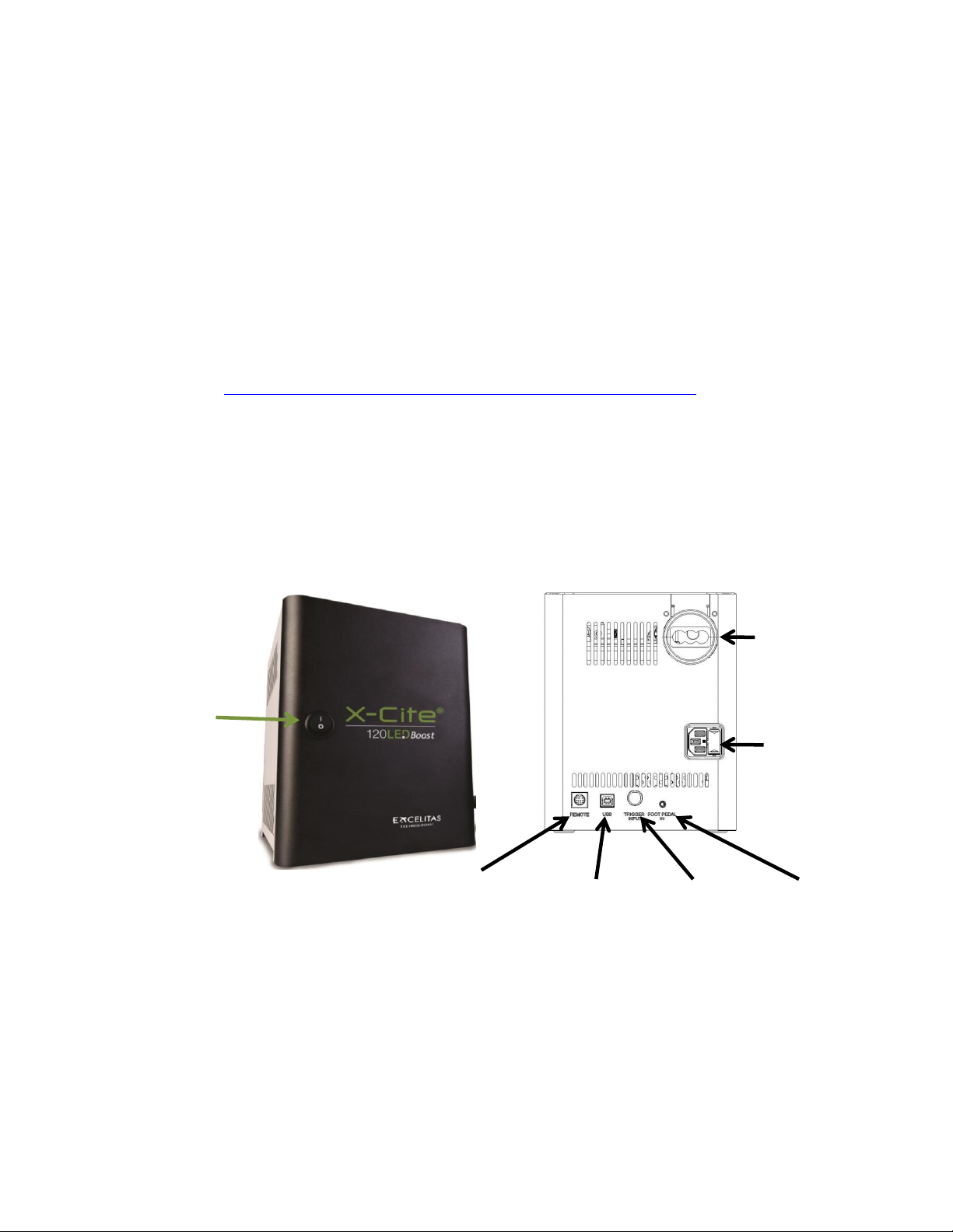
Main Power
ON/OFF
Connection to
LED Head
TTL IN
speedDIAL
IN/OUT
AC in /
Fuse Tray
USB IN/OUT
Foot Pedal IN
3.1 System Components
The X-Cite® 120LEDBoost system contains the following components:
1. LED Head and powerCUBE (connected via 1.5m cable)
2. SpeedDIAL Manual Controller
3. Microscope Flange
4. Accessories Box, containing:
a. Quick Start Instruction Sheet (User Guide, Software and Driver downloads:
http://www.excelitas.com/Pages/Product/X-Cite-120LEDBoost.aspx)
b. Hex Tool, 3mm
c. USB Cable
d. Power Cord
e. Safety Precautions Booklet
If any components are missing or appear damaged, please contact Excelitas Technologies immediately.
Figure 1 PowerCUBE Front and Rear Panels
8
X-Cite® 120LEDBoost User Guide
035-00536R rev. 4

Protective Cover
Vents on Bottom
Rotating Dial
Display Screen (LCD)
Figure 2 LED Head
Figure 3 SpeedDIAL
3.2 Installation/Set-up
1. Unpack
X-Cite® 120LEDBoost User Guide
035-00536R rev. 4
a. Carefully unpack the unit and accessories from the shipping carton.
b. When removing the LED Head and powerCUBE from the carton, ensure that both
components are supported and there is always some slack in the cable. Excessive strain
on the cable may damage or weaken the connection.
c. Do not use the cable as a “handle”. PowerCUBE is packed with a cardboard insert with
handles to assist in removing it from the protective foam. Set aside the insert and
support powerCUBE from the bottom as soon as it is possible to do so. The insert will
not support the full weight of the unit for an extended period of time, and the handles
may tear.
9
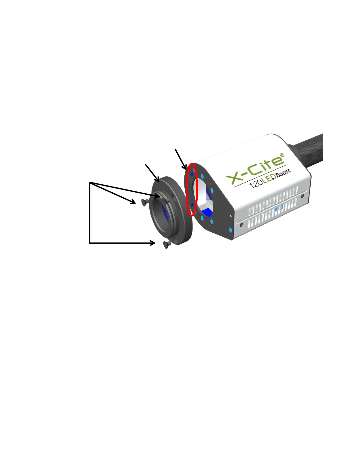
2. Install the Microscope Flange
Dowel Pins
Microscope Flange
Hex Fasteners (3)
a. Remove protective wrap from the Microscope Flange, being careful not to touch the
lens surfaces.
b. Remove protective cap from LED Head. Never power up the unit with this cap installed
– it can melt very quickly at high power settings and damage the unit.
c. Align the mounting holes on the Microscope Flange and the LED Head. Attach the
Microscope Flange using the Hex Tool and three (3) fasteners provided. The two (2)
dowel pins on the LED Head will allow you to install the Flange quickly and in the proper
position as required by your microscope.
Figure 4 Installing Microscope Flange on LED Head
3. Position the equipment
a. TIP: The cable connecting the LED Head and powerCUBE has limited flexibility, so take a
moment to position the equipment before connecting it.
b. PowerCUBE should be positioned to avoid sharp bends and strain on the cable,
preferably on the same level as the microscope or slightly above it on a low shelf.
c. The front panel of powerCUBE should be within reach to access the main power switch.
(During operation, all other functions are controlled via speedDIAL or USB interface.)
d. Air vents on both sides of powerCUBE should be clear of obstruction. Recommended
clearance is 20cm (8 inches) on all sides.
X-Cite® 120LEDBoost User Guide
035-00536R rev. 4
10

4. Connect LED Head to Microscope
Orientation Arrow
(“This Way Up”)
a. Insert Microscope Flange portion of the LED Head into the light port on the microscope,
and secure it using the hardware provided on the microscope. (Refer to relevant
microscope user manual for complete instructions on mounting a standard epifluorescence lamphouse.) General guidelines:
i. Carl Zeiss – Tighten the hex fastener on the side of the light port with the 3mm
Hex Tool.
ii. Leica - Tighten the hex fastener on the side of the light port with the 3mm Hex
Tool.
iii. Nikon – Line up the Microscope Flange “notch” with the pin on the microscope
fitting, hold the LED head firmly against the light port, and twist the collar to
lock the components together.
iv. Olympus - Tighten the hex fastener(s) with the 3mm Hex Tool. Depending on
the model, there may be one (1) fastener on the side, or two (2) fasteners
located at the 10:00 and 2:00 positions. Note for IX3-RFAL use: the epi-light
train aperture MUST be properly aligned before turning on X-Cite®
120LEDBoost, or heat damage may result - see procedure in Olympus manual
for assistance.
b. Verify that LED Head is oriented with air vents facing downwards and the arrow label is
pointing up (see Figure 5). Adjust position if necessary – operating X-Cite® 120LEDBoost
with the LED Head at an angle will affect performance and may cause damage long
term.
c. Verify that the LED Head is securely fastened by attempting to gently rock it from side to
side.
5. Connect speedDIAL to powerCUBE
X-Cite® 120LEDBoost User Guide
035-00536R rev. 4
Figure 5 LED Head and Arrow in Correct Position
a. Insert the mini DIN plug into the “Remote” port on the rear of the powerCUBE. Ensure
the arrow mark on the connector is on top and centered. Note: Never force the
11

connector – this can damage the pins. If connector does not insert smoothly, stop and
check for bent pins.
b. Place speedDIAL next to the microscope, or another easily accessible location.
6. Connect USB (if using)
a. Insert “B” (square) end into the “USB” port on rear of the powerCUBE.
b. Insert “A” (flat) end into an available port on the computer.
c. Note: For best performance, use the supplied USB cable or one of equivalent quality
and length. Using a longer USB cable than the one supplied may result in intermittent
communication errors.
7. Connect AC Power
a. Connect female end to AC port on rear of the powerCUBE.
b. Connect male end to a properly grounded electrical outlet.
c. For safe operation, use only the power cord supplied or one with an equivalent rating.
4 Operation – Manual Control
4.1 The Basics
1. Start the unit
a. Flip the rocker switch on the front of powerCUBE to turn X-Cite® 120LEDBoost on.
b. The system will have a brief initialization period (approximately 10 seconds). The
speedDIAL display will show “X-Cite” during this time.
c. When the display shows “x%”, it is ready to use.
d. Note: If speedDIAL will be used for manual control, it must be connected before turning
system on. SpeedDIAL can be damaged if it is plugged into, or unplugged from, the
system while it is powered on.
2. Illuminate a specimen
a. Click the dial (shutter button) on speedDIAL to turn on/off the excitation light.
3. Adjust intensity
a. Turn the dial to adjust intensity - clockwise to increase, counter-clockwise to decrease.
b. The dial is speed sensitive – turning slowly will allow adjustments in smaller increments,
turning quickly will increase the step sizes.
X-Cite® 120LEDBoost User Guide
035-00536R rev. 4
12

4.2 SpeedDIAL Home Screen
LED ON
TTL Mode
Enabled
speedDIAL Locked
(via Computer)
LED Power Level
Figure 6 SpeedDIAL Home Screen Icons
4.3 SpeedDIAL Menu and Settings
In addition to the intuitive intensity adjustment and illumination ON/OFF control, speedDIAL has several
advanced settings and control options.
To access the main menu, press and hold the dial for one (1) second.
To navigate the menus, turn the dial to scroll through the options. An arrowhead will indicate
the currently selected menu option; click the dial to make a selection.
To adjust settings, turn the dial. To exit the setting adjustment, click the dial.
To exit menu system at any time, press and hold the dial for one (1) second.
Note: Setting changes will take effect immediately after selection. However, for the first five (5)
minutes, the new settings are stored in a temporary memory location. If X-Cite® 120LEDBoost is
powered down during this time, settings will revert back to their previous values. To ensure that new
settings will be remembered, wait at least five (5) minutes before powering down the unit.
X-Cite® 120LEDBoost User Guide
035-00536R rev. 4
13

4.3.1 SpeedDIAL Menu Structure
LCD
Dim
Brig
Color
Exit
Favo
Int
Enbl
Spd
Exit
TTL
Enbl
Time
Exit
Hand
Srvc
Hour
SN
Tmp1
Tmp2
S/W1
S/W2
Exit
Exit
4.3.2 LCD – Display Screen Brightness and Color Settings
In the LCD sub menu, the backlight on the display screen can be turned on/off, set to a different
brightness level, or set to a different color.
a. Select the “LCD” option from main menu.
b. To adjust LCD display backlight time out:
i. Select “Dim” and scroll through the time out options, which are: Off and 1 thru
999 seconds in 1 second increments. “Off” will turn off the backlight timer (i.e.
backlight will always be on).
ii. Click dial to save selection and return to “LCD” menu.
c. To adjust LCD brightness:
i. Select “Brig” and scroll through % brightness settings until the desired level is
reached. To turn backlight off, set level to 0%.
ii. Click dial to save selection and return to “LCD” menu.
d. To change LCD color:
X-Cite® 120LEDBoost User Guide
035-00536R rev. 4
14

i. Select “Color” and scroll up /down through the options until desired color is on
LCD.
ii. Click dial to save selection and return to “LCD” menu.
e. Select “Exit” to go back to the main menu, or press and hold dial to return to the home
screen.
4.3.3 Favo – Favorite Intensity Setting
In the FAVO sub menu, a favorite, commonly used intensity setting can be saved. When this
mode is enabled, the intensity level will instantly jump to this setting with a double-click of the
dial. A second double-click will toggle back to the previous intensity level.
a. Select “Favo” option from main menu.
b. To set/change the favorite intensity:
i. Select “Int” and scroll through % intensity settings until the desired level is
reached.
ii. Click dial to save selection and return to “Favo” menu.
iii. TIP: Scrolling through % settings in this menu will not actually change the output
in real time, even if LED is on. The favorite intensity should be determined
before entering this menu.
c. To enable/disable favorite intensity mode:
i. Select “Enbl” and scroll up/down to the desired setting.
“On” will enable (i.e. double-click speedDIAL = Favorite setting)
“Off” will disable (i.e. double-click speedDIAL = do nothing)
ii. Click dial to save selection and return to “Favo” menu.
d. To adjust the delay between clicks in the “double-click”:
i. Select “Spd” and scroll up/down to the desired delay setting. “1” will provide
the shortest delay, “10” will be the longest.
ii. Click dial to save selection and return to “Favo” menu.
iii. TIP: If double-clicking results in the light being turned OFF instead of going to
favorite intensity, increase the delay setting.
iv. Note: Setting long delay times will result in a longer response time for regular
ON/OFF control with speedDIAL (the system must wait to see if the single-click
turns into a double-click). Response times for TTL, USB or foot pedal on/off
control will not be affected.
4.3.4 TTL –TTL Mode Control
In the TTL menu, TTL mode can be enabled for experiments that require rapid LED ON/OFF
control. For further information on TTL mode, refer to the External Control, TTL section 5.2.
NOTE: TTL mode MUST be enabled for the system to respond to a TTL signal.
a. Select “TTL” option from main menu.
b. To enable/disable TTL mode:
i. Select the “Enbl” menu item.
ii. Scroll to the desired setting, “On” to enable TTL or “Off” to disable TTL.
X-Cite® 120LEDBoost User Guide
035-00536R rev. 4
15

iii. Click dial to save selection and return to “TTL” menu.
c. To define the TTL timeout setting:
i. Select the “Time” menu item.
ii. Scroll through the time out options, which are: Never and 4 to 24 hours in half
hour increments. “Never” will turn off the timeout feature (i.e. the cooling
system and driver will always be active when TTL mode is enabled).
iii. Click dial to save selection and return to “TTL” menu.
4.3.5 Hand – Display Screen Orientation
In this menu, the LCD orientation can be rotated 180°. This allows operators to use speedDIAL
on the left or right side of the microscope without blocking the view of the display with their
hand.
a. Select “Hand” option from main menu.
b. Turn dial to toggle between “Right Hand” and “Left Hand” operation. Note that the
screen will flip while adjusting this setting.
c. Click dial to save selection and return to the main menu.
4.3.6 Srvc – Service Data
In the Service menu, information specific to each X-Cite® 120LEDBoost unit can be found. This
includes total hours accumulated on the LED, unit serial number, temperatures measured at
specific locations in the unit, and embedded software versions for powerCUBE and speedDIAL.
Excelitas Tech Support personnel may request some or all of this information during a support
call.
a. Select “Srvc” option from main menu.
b. To obtain the LED “in use” hours:
i. Select the “Hour” menu option.
ii. LED “hours of use” will be shown in one (1) hour increments from 0 to 999
hours. Due to space limitations on the LCD, when 1000 hours are logged, the
format will change to “1.0k hours”, and increments will increase to 100 hours
(e.g. 1142 hours will display as “1.1k hours”). The precise hour-by-hour data will
continue to be available via USB communication.
iii. Click dial to return to “Srvc” menu.
c. To obtain the unit serial number:
i. Select the “SN” menu option.
ii. Serial number of the unit will be shown.
iii. Click dial to return to “Srvc” menu.
d. To obtain current system temperatures:
i. Select “Tmp1” or “Tmp2” as required.
ii. Temperature will be shown in degrees Celsius.
iii. Click dial to return to “Srvc” menu.
e. To obtain the embedded software version numbers:
i. Select the “S/W1” or “S/W2” menu items.
X-Cite® 120LEDBoost User Guide
035-00536R rev. 4
16

ii. The software version numbers will be shown in the format X.X.X.
iii. Click dial to return to “Srvc” menu.
5 Operation - External Control
5.1 USB/RS-232
A virtual COM port driver must be installed to enable Windows communication via the USB port. For
computers running Windows which are connected to the internet, the driver will install automatically.
For manual installation, the driver is available as a software download from the Excelitas website. Note
that administrator privileges may be required to install drivers on your computer, in which case you may
need to contact your IT department for assistance.
5.1.1 Driver Installation (via internet)
For these instructions: internet is required, Windows 7 prompts are listed
a. Ensure X-Cite® 120LEDBoost is powered off.
b. Ensure X-Cite® 120LEDBoost is connected to the computer with the USB cable.
c. Ensure computer is connected to internet.
d. Power on X-Cite® 120LEDBoost.
e. Driver installation will begin automatically. A dialogue box will confirm installation has
started.
i. If the dialogue box reports that Driver installation was not successful, click on
Get Details.
ii. Click on option to Change Settings to Automatically search Windows for
drivers. Confirm Yes, do this automatically, and save changes.
f. A second dialogue box will confirm successful installation and provide a COM port
number. Note the COM port number for use in other software applications.
5.1.2 Driver Installation (via ZIP file)
For these instructions, download the driver ZIP file from the Excelitas website
(http://www.excelitas.com/Pages/Product/X-Cite-120LEDBoost.aspx).
a. Ensure X-Cite® 120LEDBoost is powered off.
b. Ensure X-Cite® 120LEDBoost is connected to the computer with the USB cable.
c. Prepare the driver files by extracting and saving the files into a folder on the desktop (or
another easily accessible location).
d. Power on X-Cite® 120LEDBoost.
e. The “new hardware found” wizard will appear. Select No to search Windows update for
the software. Click Next to continue.
f. Select Install from a list or specific location (Advanced) to locate the driver and click
Next. Select Include this location in the search: and browse to the location on your
hard drive where unzipped files were saved in step c. Click Next.
X-Cite® 120LEDBoost User Guide
035-00536R rev. 4
17
g. Wait for installation to complete. Click Finish.
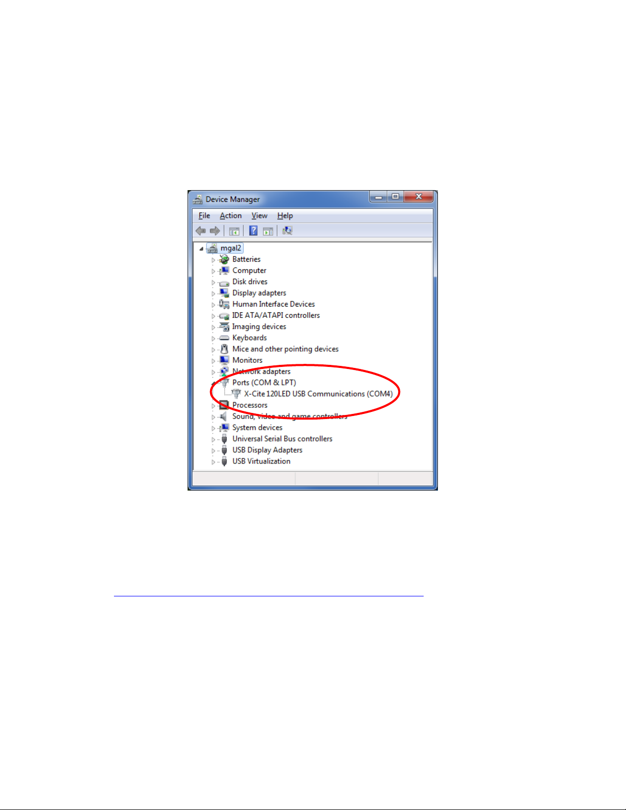
5.1.3 Verify Installation & Get COM Port Number
a. Open the “Device Manager” utility on the computer.
b. “X-Cite 120LED USB Communications” will be listed under “Ports (COM & LPT)”.
c. Note the COM port number for use in other software applications.
Figure 7 Device Manager, COM Port Listing
5.1.4 X-Cite® Control Panel / GUI installation
For these instructions, download the driver ZIP file from the Excelitas website
(http://www.excelitas.com/Pages/Product/X-Cite-120LEDBoost.aspx).
a. Uninstall any previous versions of X-Cite® Control Panel/GUI. (Previous versions
released under the EXFO name will not be automatically replaced by versions 1.1.0 or
later, and may cause confusion.)
b. Prepare the driver files (if not already done in previous section) by extracting and saving
the files into a folder on desktop (or another easily accessible location).
c. To begin installation, go to unzipped files from step b, double-click on setup.exe or
setup
d. Setup Wizard will open. Follow prompts and click Close when Wizard is finished.
X-Cite® 120LEDBoost User Guide
035-00536R rev. 4
18

e. To find GUI, go to: Start, All Programs, Lumen Dynamics, X-Cite Control Panel. Click to
ICON
NAME
DESCRIPTION
Alarm
Green = All OK
Red = Alarm on
Click will clear alarm, unless unsafe to ignore
Temperature
Indicates system temperature status
Yellow = warning, LED temp above normal
Red = LED off, temp is too high
Calibration
Not applicable for X-Cite® 120LEDBoost
LED Hours of Use
Power Level
Hide/Unhide Controls
Control Icons
start/open GUI, or click-and-drag to copy a shortcut to desktop or Quick Launch toolbar.
5.1.5 X-Cite® Control Panel – Tips for Use
a. X-Cite® Control Panel is available as a download from the Excelitas website. This tool
provides an interface for controlling the X-Cite® 120LEDBoost via PC and general testing
of the communication port.
b. Note that X-Cite® Control Panel is designed to function with multiple X-Cite® devices,
and not all icons and features can be used with all devices. See the icon table below to
determine which icons are relevant to control of X-Cite® 120LEDBoost.
c. Icon color code:
i. Green icons mean status is OK and/or the function is engaged
ii. Yellow icons mean a warning or “getting ready”
iii. Red icons mean there is an alarm condition
iv. Grey icons mean a feature is not engaged, and/or not available
v. If icons are ALL grey, X-Cite® 120LEDBoost is not connected and/or turned off
X-Cite® 120LEDBoost User Guide
035-00536R rev. 4
Figure 8 X-Cite® Control Panel
19

LED Hours
Indicates hours logged on LED
Green = <20K hours, yellow = >20K hours, red = >40K hours
Light Guide
Not applicable for X-Cite® 120LEDBoost
Shutter
Click to turn LED on/off
Intensity
Left mouse click = increase by 1% increment.
Right mouse click = decrease by 1% increment.
Left double click = opens dialog box type in value
Closed-Loop
Feedback
Not applicable for X-Cite® 120LEDBoost
Lock/unlock
Lock/unlock speedDIAL control
Green = speedDIAL is locked
Grey = speedDIAL is unlocked
Lamp
Not applicable for X-Cite® 120LEDBoost
5.1.6 Commercial Software Support
a. X-Cite® 120LEDBoost can be controlled through many commercially available packages.
Where X-Cite® 120LEDBoost specific control may not be available, basic functionality
can be achieved using X-Cite® 120PC or X-Cite® exacte hardware drivers. For an
updated list of software packages that support X-Cite® products, see
http://www.excelitas.com/Downloads/XCite-softwareSupport.pdf
b. For commercial software packages, if requested specify the serial port parameters as:
19,200 baud, no parity, 8 data bits and 1 stop bit.
c. When controlling X-Cite® 120LEDBoost, some commercial software packages may block
manual input from speedDIAL. The lock icon will appear on the speedDIAL display in
these cases.
5.1.7 Software Developer’s Kit (SDK)
The command list for X-Cite® 120LEDBoost is available by request. To obtain the latest update,
please contact Excelitas Technologies.
5.2 TTL
For high speed LED on/off control, TTL triggering can be used. The key thing to note about TTL control in
the X-Cite® 120LEDBoost is: TTL mode MUST be enabled for the system to respond to a TTL signal.
5.2.1 TTL Mode
TTL mode ensures that X-Cite® 120LEDBoost’s cooling system and LED driver are active between
exposures, ensuring the fastest possible response to a TTL signal.
X-Cite® 120LEDBoost User Guide
035-00536R rev. 4
20

Enabling/disabling TTL mode can be accomplished manually via speedDIAL (refer to
LED off
Timeout clock
LED on
(response at maximum)
Time
elapses
LED on
wake up)
@ time <4h,
TTL = high
@ 4hrs
TTL = high
TTL = low
TTL = low
TTL mode times out
(drivers/cooling turn off,
TTL mode remains)
section 4.3.4) or via computer commands (refer to SDK).
ON/OFF status of the system will be updated on speedDIAL when it is controlled via TTL.
5.2.2 TTL Mode Timeout
There is a potential disadvantage of TTL mode - in this “always active” state, the system
continues to consume energy and mechanical components accumulate wear. To help minimize
unnecessary consumption at the end of an imaging session (or if equipment is accidentally left
on), X-Cite® 120LEDBoost is equipped with a TTL timeout setting. The factory default for the TTL
timeout setting is “Never”, but defining a timeout is recommended for any imaging session that
will end without an operator present to shut down equipment (e.g. middle of the night).
Figure 9 Sequence of Events for TTL Mode Timeout (set to 4 hours)
resets, begins
countdown
(unit stays active)
(after drivers and cooling
X-Cite® 120LEDBoost User Guide
035-00536R rev. 4
21

5.2.3 TTL Timing Diagram
Interval
Description
Time (µs)
T1
Delay time, TTL trigger on to LED on
100 @ 100% power
T2
Delay time, TTL trigger off to LED off
30
TTL
LED Status
High
ON
Low
OFF
This plot shows typical TTL timing values. These values should be used as a guide only. Actual
values will be dependent on the specific configuration/control hardware being used.
5.2.4 TTL Signal and LED Status
5.2.5 TTL Input Specifications
a. Connector type: BNC (female port)
b. Maximum low level : +0.8V
c. Minimum high level : +2.2V
d. Maximum high level: + 5.5V
e. Typical input current: 800µA
5.3 Foot Pedal Control (Optional)
For hands-free operation, a foot pedal can be used to manually turn the LED on and off. The foot pedal
is an optional accessory and can be purchased separately from Excelitas Technologies.
1. Installing the foot pedal
a. Locate the “FOOT PEDAL IN” / “FP IN” input port on the rear panel of X-Cite®
120LEDBoost.
b. Insert foot pedal plug.
c. Place foot pedal on floor.
2. Operating the foot pedal
a. Press and release pedal with your foot to toggle LED on and off.
b. On/off status of LED will be shown on speedDIAL display.
X-Cite® 120LEDBoost User Guide
035-00536R rev. 4
22

c. If desired, the foot pedal can be used in combination with speedDIAL (e.g. turn on with
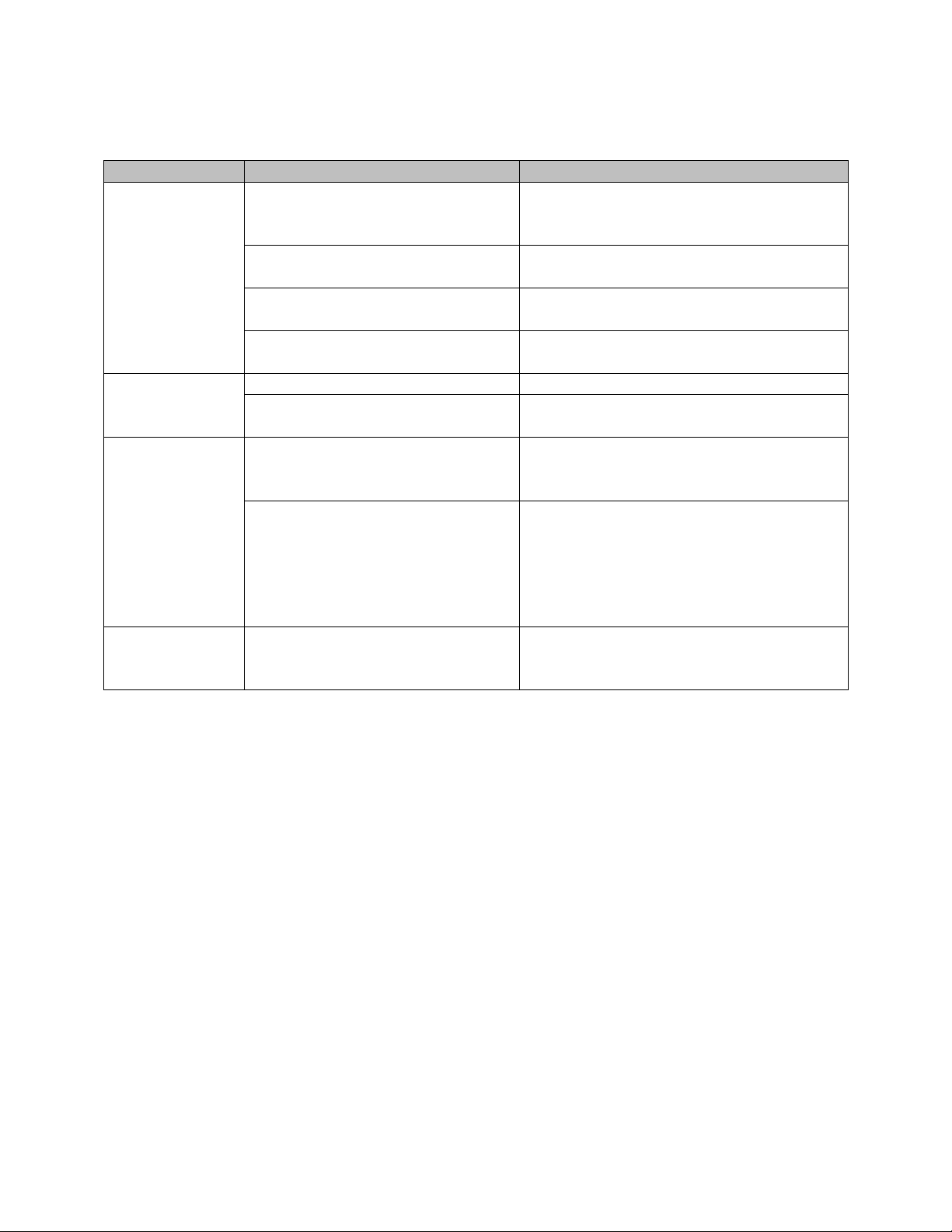
Error Code
Description
Action
1
LED has exceeded maximum
operating temperature
Turn off the system and wait for the LED to cool
down. Verify that the system has been installed with
adequate clearance for ventilation, especially around
vents on powerCUBE and LED Head. If fan is not
running or the problem persists contact technical
support for assistance.
3 or 5
Internal Error
Power cycle the X-Cite® 120LEDBoost unit. If the
error message reappears contact technical support
for assistance.
6
LED is below minimum
operating temperature
Ensure the room temperature is within the
recommended operating limits. If unit has been
stored / transported in a cold environment, allow it to
warm up to room temperature and restart. If the
problem persists contact technical support for
assistance.
speedDIAL, turn off with foot pedal.) The ON/OFF status of the system will be reflected
on speedDIAL’s home screen whether it is changed via the foot pedal or by any other
means.
6 Troubleshooting
Organized by symptom, this section provides basic troubleshooting information for installation and setup parameters. X-Cite® 120LEDBoost may be serviced by authorized technical personnel only.
6.1 Error Messages
If X-Cite® 120LEDBoost detects a problem, an error message with one of the following codes will appear
on the speedDIAL display.
6.2 Failure to Power Up
If X-Cite® 120LEDBoost fails to POWER up or function properly, use the following checklist to eliminate
the most common causes of problems. Check for the following:
1. Power Connection Check:
a. The power supply cord is securely connected to a grounded (earthed mains socket)
functional outlet.
b. The power supply cord is securely connected into the 3-pin outlet on the rear of the
controller unit.
c. The main AC power switch is in the ON position.
X-Cite® 120LEDBoost User Guide
035-00536R rev. 4
23

2. Fuse Check:
A B C
a. Check both main power fuses. First disconnect the power cord, then carefully remove
the fuse tray assembly next to the AC receptacle on the rear of the unit. Note:
depending on the orientation of the AC receptacle, the fuse tray may be below or beside
it. The red arrow in figure 10 (A) shows where a flat screwdriver can be inserted to
gently lever out the fuse tray.
Figure 10 Location and Removal of Fuse Tray in AC Receptacle
b. If either or both of the fuses are open, replace with the same type (4A, 250V).
c. Note: To determine if a fuse is intact (i.e. OK) or open (i.e. blown), remove the fuse
from the tray and check with a multi-meter set to resistance (Ω). An intact fuse will read
“0Ω” (or another very low value), an open fuse will have an extremely high Ω reading.
d. Note: Fuses that chronically need replacing are usually a signal that something is wrong
and Technical Support should be contacted.
3. SpeedDIAL Check:
a. Verify that the pins on speedDIAL connector are straight.
b. Verify that speedDIAL is plugged securely into powerCUBE.
6.3 Low Illumination Intensity
1. SpeedDIAL Setting Check:
a. Verify that the LED intensity is set to a sufficient level.
b. Verify that the LED Head is turning on.
2. Microscope Check:
a. Verify that the Microscope Flange is appropriate for the microscope configuration.
Note: Some flanges have the same mechanical fitting but different optics.
b. Verify that everything in the microscope beam path is properly aligned and open, e.g.
shutters, apertures, diaphragms, filters, filter cubes, etc.
c. Verify that microscope filter sets are for the appropriate wavelengths.
d. Verify that air objectives are clean / immersion objectives have enough of the
appropriate fluid.
24
X-Cite® 120LEDBoost User Guide
035-00536R rev. 4
6.4 Other Potential Symptoms & Questions
Category
Symptom
Action
speedDIAL
Favorite intensity setting: doubleclick turns off LED instead of going to
the stored setting
Increase delay in the speed (Spd) setting.
New settings are forgotten when
unit is shut down and powered up
After changing settings, wait at least five (5)
minutes before shutting unit down.
Turning dial does not scroll through
the menu options
Turn dial in the opposite direction.
“Lock” icon is on display, speedDIAL
not responding to manual control
Send “unlock” command via computer OR
power down unit and restart.
TTL Triggering
TTL signal does not trigger unit
Enable TTL mode.
TTL response time is longer than
usual
Verify that timeout settings are
appropriately set.
Audible Noise
PowerCUBE fan never turns off, even
when LED is not on
Fan continues to run for five (5) minutes
after LED is turned off. If it runs longer,
disable TTL mode (it is likely enabled).
Bubbling noise is coming from LED
Head.
Disconnect LED Head from microscope and
move to a position lower than powerCUBE.
Set LED to 1%, turn on, and run for several
minutes until noise stops. When
remounting LED Head to microscope, ensure
arrow label is pointing straight up.
Output Linearity
Plotting output power vs. intensity
setting is not a straight line
No action. “x%” shown on speedDIAL refers
to LED input current, which is not
necessarily linear with optical output.
7 Routine Care and Maintenance
7.1 General
X-Cite® 120LEDBoost is a very low maintenance system with no consumable components. By
maintaining the following conditions, performance will be maximized and risk of future problems will be
reduced.
1. Maintain a clean work area, keeping the X-Cite® 120LEDBoost air vents unobstructed.
2. Ensure that the cable connecting the powerCUBE and LED Head has some slack in it and is never
cut, stretched, kinked, or forced into a sharp bend.
3. If X-Cite® 120LEDBoost must be moved, ensure that both the powerCUBE and the LED Head are
supported. Never use the cable as a handle.
4. Never leave the internal optics of the LED Head exposed. When not connected to a microscope,
ensure the output port is always covered by a Microscope Flange or the supplied protective
plastic cover.
X-Cite® 120LEDBoost User Guide
035-00536R rev. 4
25

5. Never touch optical surfaces with fingers, tools or any other abrasive/sticky/sharp materials or
fluids.
6. If cleaning is required, follow the directions in the next section.
7.2 Cleaning - Exterior Surfaces
If necessary, exterior surfaces of X-Cite® 120LEDBoost’s LED Head, powerCUBE and speedDIAL can be
cleaned with a mild soap and water solution and lint-free cloth.
1. Turn unit off and disconnect AC power prior to cleaning.
2. Use a damp cloth only - do not allow cleaning solution to get into I/O ports, air vents or seams.
3. Avoid optical surfaces.
4. Allow the unit to dry before turning it on.
7.3 Cleaning - Optical Surfaces
Cleaning of optical surfaces is not generally required. However, if any visible contamination or
fingerprints appear on the lens surface, cleaning may be necessary.
1. Recommended Cleaning Materials
a. Rubber bulb dust blower
b. Lint-free lens tissue, lint-free cotton swabs
c. Powder-free gloves or finger cots
d. Lens cleaning solution, reagent-grade isopropyl alcohol, or another appropriate solvent
2. Cleaning Procedure
a. Use rubber dust blower to blow off any loose lint, dust or other contaminant.
b. If the contaminant is a fluid (e.g. water, immersion oil), first use a dry lens tissue (or
cotton swab) to wick away as much as possible – do not wipe.
c. Saturate a corner of the lens tissue (or the cotton swab) with cleaning solvent, and
gently wipe the optical surface in one pass. Note: Take care not to “flood” the area
with solvent, particularly near unsealed joints (e.g. lens-retaining ring interface).
d. Repeat the previous step with a fresh portion of lens tissue (or new cotton swab) – this
will help avoid recontamination of the optical surface and minimize the amount of
cleaning required.
e. Let solvent evaporate and verify that the optical surface is clean. Repeat cleaning steps
as necessary.
f. Before reinstalling and/or using the optics, allow them to dry completely.
CAUTION: Before using any solvent, consult the manufacturer’s Material Safety Data Sheet (MSDS)
and your internal Health and Safety Advisor for proper handling, storage, and disposal instructions.
X-Cite® 120LEDBoost User Guide
035-00536R rev. 4
26

7.4 Thermal Management System
powerCUBE
LED Head
speedDIAL
Height
213mm (8.4″)
116mm (4.6″)
59mm (2.3″)
Width
173mm (6.8″)
90mm (3.5″)
80mm (3.1″)
Depth
260mm (10.2″)a
166mm (6.5″)
a,b
112mm (4.4″)
Weight
3.9kg (8.6lbs)
0.9kg (2lbs)
0.3kg (0.7lbs)
Power Supply
Power Factor Corrected, Universal Input
Input Voltage
100-240VAC, 50/60Hz
Current
3.0A max /100V, 1.5A max/240V
Input Surge
With cold start 40A/115V, 80A/240V
Protection
Over load and over temperature
Fuse Rating
Dual fuse system: each fuse rated at F 4.0A 250V
5x20mm type located in AC receptacle
X-Cite® 120LEDBoost’s unique thermal management system incorporates both air and liquid cooling
technologies. If the general care and maintenance guidelines described above are followed, no further
maintenance is required to ensure continued superior performance.
This robust design is similar to those used in high-powered computers, and through normal use the
liquid will remain contained. If, through accident or negligence, the cable between powerCUBE and the
LED Head is punctured or otherwise damaged, some liquid may escape. Should this occur:
1. Don’t panic.
2. Power off and discontinue using the system.
3. Elevate the damaged portion of the cable.
4. Clean spill with absorbent material. The liquid is a non-toxic mix of propylene glycol and
distilled water. Refer to Material Safety Data Sheet (MSDS), located in the Appendix.
5. Contact Technical Support.
8 Technical Specifications
8.1 General
Notes:
a. Does not include clearance required for cable, minimum 200mm (8″).
b. Does not include microscope flange, varies by type, approximately 10-15mm (0.4-0.6″).
8.2 Electrical
X-Cite® 120LEDBoost User Guide
035-00536R rev. 4
27

8.3 Environmental – Operating Conditions
Ambient Temperature
10° to 35° C
Altitude
2000m max
Atmospheric Pressure
700 to 1060 hPa
Relative Humidity
15 to 90% RH (non-condensing)
Installation Category
II
Pollution Degree
2
Enclosure Rating
1
Temperature
-35° to 60° C
Relative Humidity
10 to 95% RH (non-condensing)
Atmospheric Pressure
500 to 1060 hPa
Connection
Connection Style
Purpose
speedDIAL - IN/OUT
Mini DIN plug, 9pos
Communication between speedDIAL and
powerCUBE to control LED and report
status (on/off, intensity adjustment,
system error, etc.)
USB - IN/OUT
B
Communication between computer and
powerCUBE to control LED and report
status.
TTL - IN
BNC
External trigger to turn LED on/off
Foot Pedal - IN
3mm stereo plug
External trigger to turn LED on/off
8.4 Environmental – Transport and Storage Conditions
8.5 Input/Output (I/O) Connections
8.6 Output Stability
For maximum output stability, X-Cite® 120LEDBoost should be set to a power level of 5% or greater. At
lower power levels (<3%), some intensity fluctuation may be observed.
If an application requires lower power levels, strategies to avoid fluctuations include:
Increase power level, and reduce exposure time to compensate for brighter signal.
Increase power level, and use a neutral density filter or iris in the microscope light train to
reduce intensity to an appropriate level for the specimen.
X-Cite® 120LEDBoost User Guide
035-00536R rev. 4
28

9 Regulatory
Council Directive 2014/35/EU
Low Voltage Directive
Council Directive 2014/30/EU
EMC Directive
Council Directive 2012/19/EU
WEEE Directive
Council Directive 2011/65/EU
RoHS
9.1 Product Safety and Electromagnetic Compatibility
The X-Cite 120LEDBoost has been tested and found to comply with product safety and electromagnetic
compatibility requirements. For a complete list of tests and for certification details, please contact your
X-Cite representative or visit http://www.excelitas.com/Pages/Product/X-Cite-120LEDBoost.aspx.
9.2 CE Marking
9.3 FCC
FCC Class A Digital Device or Peripheral - Information to User
NOTE
This equipment has been tested and found to comply with the limits for a Class A digital device,
pursuant to Part 15 of the FCC Rules. These limits are designed to provide reasonable protection against
harmful interference when the equipment is operated in a commercial environment. This equipment
generates, uses, and can radiate radio frequency energy and, if not installed and used in accordance
with the instruction manual, may cause harmful interference to radio communications. Operation of this
equipment in a residential area is likely to cause harmful interference in which case the user will be
required to correct the interference at his own expense.
WARNING
Changes or modifications not expressly approved by Excelitas Technologies could void the user’s
authority to operate the equipment.
9.4 WEEE Directive
The symbol above indicates that this product should not be disposed of along with municipal waste, that
the product should be collected separately, and that a separate collection system exists for all products
that contain this symbol within member states of the European Union.
The equipment that you bought has required the extraction and use of natural resources for its
production. It may contain hazardous substances that could impact health and the environment.
29
X-Cite® 120LEDBoost User Guide
035-00536R rev. 4

In order to avoid the dissemination of those substances in our environment and to diminish the
pressure on the natural resources, we encourage you to use the appropriate take-back systems.
Those systems will reuse or recycle most of the materials of your end life equipment in a sound
way.
The crossed-out wheeled bin symbol indicated above invites you to use those systems.
If you need more information on the collection, reuse and recycling systems, please contact
your local or regional waste administration.
9.5 China RoHS
The symbol above indicates that this product is in compliance with China RoHS requirements.
X-Cite® 120LEDBoost User Guide
035-00536R rev. 4
30

10 Warranty & Repairs
SYSTEM COMPONENT
WARRANTY
WARRANTY VOID IF…
X-Cite® 120LEDBoost
powerCUBE
X-Cite® 120LEDBoost Head
1 year
• Unit has been subjected to misuse or
mishandling.
• Unit has been opened or tampered with.
X-Cite® 120LEDBoost
speedDIAL
1 year
• Unit or cabling has been subjected to misuse
or mishandling.
• Unit has been opened or tampered with.
• LCD display damage (physical).
LED assembly
(in X-Cite® 120LEDBoost
Head)
• 25,000 hrs
• 3 years
whichever
Comes first
• Cable damage due to misuse or mishandling.
• LED Head has been opened or tampered with.
• For all other LED Head components, 1 year
warranty applies.
10.1 Warranty Terms
Excelitas Technologies warrants the original purchaser for a period of one (1) full year, calculated from
the date of purchase, that the equipment sold is free from defects in material and workmanship. All
repairs are warranted for 90 days. The LED assembly within the LED Head has a warranty period of
25,000 hours of use or 3 years, whichever comes first.
In the event of a claim under this guarantee, the equipment is to be sent postage and carriage paid,
including a description of the fault, to the Excelitas Technologies Service Center. Returned equipment
will not be received without a Return Material Authorization (RMA) Number, issued by the appropriate
Service Center.
In the case of damage caused by wear and tear, careless handling, neglect, by the use of force or in the
case of interventions and repairs not carried out by an Excelitas Technologies Service Center, the
guarantee ceases to be valid. This guarantee may not form the basis for any claims for damages, in
particular not for compensation of consequential damages.
The warranty is not transferable. No warranty is extended to perishable items, such as fuses and air
filters.
Any claims for units received with defects in material or workmanship must be reported to an
authorized Excelitas Technologies Service Center within 30 days from the original date of receipt.
10.2 Returning equipment to Excelitas Technologies
1. Please make a note of the problem encountered, the steps followed to isolate the problem and
the result of any troubleshooting steps taken.
X-Cite® 120LEDBoost User Guide
035-00536R rev. 4
31

2. Contact the nearest Excelitas Technologies Service Center to obtain a Return Material
Authorization (RMA) number. For your convenience, RMA numbers can also be requested online at: http://www.excelitas.com/Pages/Support/Service-Request-Form.aspx
3. Follow shipping instructions provided by the service technician. The unit should be returned in
its original packaging if possible.
11 Contact Information
11.1 General
Excelitas Canada Inc.
Tel: (905) 821-2600 1-800-668-8752 (USA and Canada)
Fax: (905) 821-2055
1-800-668-8752 (USA and Canada)
x-cite@excelitas.com
http://www.excelitas.com/Pages/Product/X-Cite.aspx
For a list of Authorized Service Centers, visit:
http://www.excelitas.com/Pages/Support/Service-Centers.aspx
11.2 Accessories and Replacement Parts
Replacement parts and accessories can be purchased directly from Excelitas Technologies. For ordering
and pricing information contact the inside sales department at:
(905) 821-2600
1-800-668-8752 (USA and Canada)
x-cite@excelitas.com
http://www.excelitas.com/Pages/Contact/Contact-Us.aspx
X-Cite® 120LEDBoost User Guide
035-00536R rev. 4
32

Appendix
X-Cite® 120LEDBoost User Guide
035-00536R rev. 4
33

MATERIAL SAFETY DATA SHEET
Prepared to U.S. OSHA, CMA, ANSI and Canadian WHMIS Standards
_____________________________________________________
PART I What is the material and what do I need to know in an emergency?
________________________________________________________________________________
1. PRODUCT IDENTIFICATION
TRADE NAME (AS LABELED)
CHEMICAL NAME/CLASS: Heat Transfer Fluids
SYNONYMS: Inhibited Propylene Glycol
DISTRIBUTOR'S NAME: Dynalene Heat Transfer Fluids
ADDRESS: 5250 West Coplay Road
Whitehall, PA 18052
EMERGENCY PHONE: 1 -800-424-9300 (CHEMTREC)
BUSINESS PHONE: 1-610-262-9686
DATE OF PREPARATION: August 29, 2004
DATE OF REVISION: March 9, 2011
________________________________________________________________________________
CHEMICAL NAME CAS # WT %
Propylene Glycol 57-55-6 >95 NE NE NE NE NE NE
Inhibitor Solution
2. COMPOSITION and INFORMATION ON INGREDIENTS
NE = Not Established C = Ceiling Level See Section 16 for Definitions of Terms Used.
NOTE: All WHMIS required information is included. It is located in appropriate sections based on the ANSI Z400.1-1993 format.
: DYNALENE PG™
EXPOSURE LIMITS IN AIR
ACGIH OSHA
TLV STEL PEL STEL IDLH OTHER
3
mg/m3 mg/m3 mg/m3 mg/m
mg/m
Balance
None of the ingredients in the Inhibitor Solution contribute any significant,
additional hazard to these products. All pertinent hazard information has
been provided in this Material Safety Data Sheet, per the requirements of
the Federal OSHA Hazard Communication Standard (29 CFR 1910.120 0)
and State equivalent standards.
DYNALENE PG™ MSDS
PAGE 1 OF 8
3
mg/m
3

________________________________________________________________________________
(
)
________________________________________________________________________________
3. HAZARD IDENTIFICATION
EMERGENCY OVERVIEW: This product is a clear, odorless, syrupy liquid. Vapors and mists from this product
may be irritating if inhaled. The solution can be irritating to contaminated skin or eyes. This product must be
substantially preheated before ignition can occur. If involved in a fire, this liquid will release toxic gases (i.e. carbon
monoxide and carbon dioxide). This product is not reactive. Emergency responders must wear proper personal
protective equipment and have adequate fire protection for the situation to which they are responding.
SYMPTOMS OF OVER-EXPOSURE BY ROUTE OF EXPOSURE:
The most significant routes of exposure to this product are by
inhalation of the vapors and contact with the skin and eyes.
INHALATION: Inhalation of the mists or vapors of this product may be
irritating to the nose, throat, mucous membranes, and other tissues of
the respiratory system. Propylene Glycol is the main component of
this product. Vapor concentrations of Propylene Glycol are normally
too low at room temperature (due to the low vapor pressure) to cause
significant toxic effects from vapor alone.
CONTACT WITH SKIN or EYES: This product may cause local
redness or irritation of the skin. Repeated or prolonged exposure may
lead to dermatitis. Contact with the eyes will cause redness, irritation,
tearing, and possibly burning.
SKIN ABSORPTION: Based on clinical tests, skin absorption is a
potential route of over-exposure for Propylene Glycol (the main
component of this product). Symptoms of such exposure can include
symptoms described for “Contact with Skin and Eyes”.
INGESTION: Ingestion of this product, while not likely to occur in an
industrial setting, may cause irritation of the mouth and throat, gastric
upset, nausea and vomiting.
INJECTION: Though not an expected route of occupational exposure
for this product, injection (via punctur es or lacerations in the skin) may
cause local reddening, tissue swelling and discomfort.
HEALTH EFFECTS OR RISKS FROM EXPOSURE: An Explanation in Lay Terms. Symptoms associated with overexposure to this product are as follows:
ACUTE: Inhalation of the mists or vapors of this product may be irritating to the nose, throat, mucous membranes, and
other tissues of the respiratory system. This product may also be irritating to contaminated skin or eyes.
CHRONIC: Prolonged or repeated skin exposures may cause irritation, which could lead to dermatitis (dry, chapped
skin).
TARGET ORGANS: Skin, eyes.
________________________________________________________________________________
HAZARDOUS MATERIAL INFORMATION
SYSTEM
HEALTH
FLAMMA BILITY
REACTIVITY
(BLUE)
yellow
RED
0
1
0
PROTECTIVE EQUIPMENT
EYES R ESPIRATORY
For routine industrial applications
HANDS
SEE SECTION 8
BODY
PART II What should I do if a hazardous situation occurs?
________________________________________________________________________________
4. FIRST-AID MEASURES
SKIN EXPOSURE: If this product contaminates the skin, immediately begin decontamination with running water. Remove
exposed or contaminated clothing, taking care not to contaminate eyes. The minimum
minutes. Contaminated individual must seek immediate medical attention, especially if irritation or redness develops.
recommended flushing time is 15
EYE EXPOSURE: If this product enters the eyes, open victim's eyes while under gentle running water. Use sufficient
force to open eyelids. Have victim "roll" eyes. Minimum
flushing is for 15 minutes. Contaminated individual must seek
immediate medical attention, especially if symptoms persist.
INHALATION
respiration to support vital functions. Remove or cover gross contamination to avoid exposure to rescuers.
: If vapors or mists of this product are inhaled, remove victim to fresh air. If necessary, use artificial
DYNALENE PG™ MSDS
PAGE 2 OF 8

INGESTION: Hazards from swallowing this product is not expected to be serious. If symptoms develop, seek medical
attention.
___________________________________________________________________________________________________________
________________________________________________________________________________
5. FIRE-FIGHTING MEASURES
NFPA RATING
The following information is available for Propylene Glycol, the main component of this
product.
FLASH POINT, °C (method): 99°C (210°F), Closed Cup
AUTOIGNITION TEMPERATURE, °C: 371°C (700°F)
FLAMMABLE LIMITS (in air by volume, %): Lower (LEL): 2.6%
Upper (UEL)
The following information is available for this product.
: 12.5%
FIRE EXTINGUISHING MATERIALS:
HEALTH
FLAMMABILITY
1
0
OTHER
0
REAC
Water Spray: YES (cooling only) Carbon Dioxide: YES Foam: YES
Dry Chemical: YES Other: Any "ABC"Class Halon: YES
UNUSUAL FIRE AND EXPLOSION HAZARDS: This product must be substantially
pre-heated before ignition can occur. When involved in a fire, this material may decompose and produce irritating vapors
and toxic gases (e.g., carbon oxides).
Explosion Sensitivity to Mechanical Impact: Not sensitive.
Explosion Sensitivity to Static Discharge: Not sensitive.
SPECIAL FIRE-FIGHTING PROCEDURES: Incipient fire responders should wear eye protection. Structural fire fighters
must wear Self-Contained Breathing Apparatus and full protective equipment. Move fire-exposed containers if it can be
done without risk to firefighters. If possible, prevent run-off water from entering storm drains, bodies of water, or other
environmentally areas. Decontaminate fire-response equipment with soap and water solution if necessary.
________________________________________________________________________________
6. ACCIDENTAL RELEASE MEASURES
SPILL AND LEAK RESPONSE: Uncontrolled releases should be responded to by trained personnel using pre-planned
procedures. Proper protective equipment should be used. In case of an uncontrolled release, clear the affected area,
protect people, and respond with trained personnel.
SMALL SPILL: Cover with absorbent material (floor absorbent, vermiculite, etc.) Soak up spill and place material into a
drum.
LARGE SPILL: Personnel involved with large releases should wear protective equipment. Stop spill at source, dike the
area surrounding the spill to prevent further exposure. Prevent material from entering sewer system. If pump is available,
pump spilled material into 55-gallon drums for proper disposal. If necessary, absorbents such as vermiculite, clay floor
absorbent may be used on spill and shoveled into drums.
Personal Protective Equipment should be Level D: chemical resistant gloves (rubber gloves and Nitrile gloves), and
coveralls, safety glasses, safety shield. If heated, this product may displace oxygen in an enclosed area.
Monitoring of oxygen level is recommended. Decontaminate the area thoroughly. If necessary, decontaminate spill
response equipment with soap and water solution. Dispose of in accordance with Federal, State and local hazardous
waste disposal regulations (see Section 13, Disposal Considerations).
___________________________________________________________
PART III How can I prevent hazardous situations from occurring?
_________________________________________________________________________________________________________________________________________________________________
7. HANDLING and STORAGE
WORK PRACTICES AND HYGIENE PRACTICES: As with all chemicals, avoid getting this product ON YOU or IN YOU.
Wash thoroughly after handling this product. Do not eat or drink while handling these materials. Use in a well-ventilated
location. Use ventilation and other engineering controls to minimize potential exposure to the aerosol, sprays and vapors
of this product. Remove contaminated clothing immediately.
DYNALENE PG™ MSDS
PAGE 3 OF 8

_____________________________________________________
_____________________________________________________
7. HANDLING and STORAGE
STORAGE AND HANDLING PRACTICES: All employees who handle this material should be trained to handle it safely.
Use in a well-ventilated location. Open drums and other containers of this product slowly, on a stable surface. Drums
and other containers of this product should be properly labeled. Empty drums and containers may contain residual
amounts of this product, therefore, empty containers should be handled with care. Move drums of this product carefully,
with the appropriate drum-handling equipment.
Store drums and other containers in a cool, dry location, away from direct sunlight, or sources of intense heat. Storage
areas should be made of fire-resistant materials. Keep containers away from incompatible chemicals (See Section 10,
Stability and Reactivity).
________________________________________________________________________________
8. EXPOSURE CONTROLS - PERSONAL PROTECTION
VENTILATION AND ENGINEERING CONTROLS: Use with adequate ventilation. General methods include mechanical
(local exhaust) ventilation, process or personnel enclosure and control of process conditions. Local exhaust ventilation
may be necessary when this material is heated or a mist created. Supply sufficient replacement air to make up for air
removed by exhaust system. Prudent practice is to ensure eyewash/safety shower stations are available near areas
where This product is used.
RESPIRATORY PROTECTION: None needed for normal circumstances of use. If respiratory protection is needed, use
only protection authorized in 29 CFR 1910.134, or applicable State regulations. Use supplied air respiration protection if
oxygen levels are below 19.5% or are unknown.
EYE PROTECTION: Splash goggles or safety glasses.
HAND PROTECTION: Wear butyl rubber, natural rubber, neoprene, Nitrile rubber, or other suitable gloves for routine
industrial use.
BODY PROTECTION: Use body protection appropriate for task.
PERSONAL PROTECTIVE EQUIPMENT LEVEL: D
________________________________________________________________________________
Unless otherwise specified, the following information is available for Propylene Glycol, the main component of this
product.
RELATIVE VAPOR DENSITY (air = 1): 2.62
FREEZING/MELTING POINT or RANGE: At 95% Concentration: -51°C (-60°F) (Product)
EVAPORATION RATE (n-BuAc=1): Not available.
SPECIFIC GRAVITY (water = 1): 1.038
SOLUBILITY IN WATER: Soluble.
VAPOR PRESSURE, mm Hg @ 20 °C: 0.07
ODOR THRESHOLD: Not applicable.
COEFFICIENT WATER/OIL DISTRIBUTION: Log P (oct) = -1.41, -0.30
BOILING POINT: 188°C (371°F)
pH: Approximately 8.9
APPEARANCE AND COLOR: This product is a colorless, odorless, syrupy liquid with a faint, chemical odor. Alternate
colors are available, pending customer preferences.
HOW TO DETECT THIS SUBSTANCE (warning properties): The appearance is a distinguishing characteristic of this
product.
9. PHYSICAL and CHEMICAL PROPERTIES
DYNALENE PG™ MSDS
PAGE 4 OF 8

_____________________________________________________
________________________________________________________________________________
STABILITY: Stable.
DECOMPOSITION PRODUCTS: Mainly carbon dioxide and carbon monoxide.
10. STABILITY and REACTIVITY
MATERIALS WITH WHICH SUBSTANCE IS INCOMPATIBLE: Strong oxidizers, strong acids, acid chlorides, acid
anhydrides, chloroformates, or strong reducing agents.
HAZARDOUS POLYMERIZATION: Will not occur.
CONDITIONS TO AVOID: Contact with incompatible chemicals.
________________________________________________
PART IV Is there any other useful information about this material?
_________________________________________________________________________________________________
TOXICITY DATA: Additional toxicology information for components greater listed in Section 2 (Composition and
Information on Ingredients) in concentration is provided below.
PROPYLENE GLYCOL:
Skin-Human: 500 mg/7 Days; Mild irritation effects
Skin-Human: 104 mg/3 days - Intermittent, Moderate irritation effects
Skin-Man 10%/2 days
Eye effects-Rabbit, adult : 100 mg, Mild irritation effects
Eye effects-Rabbit, adult: 500 mg/24 hours, Mild irritation effects
DNA Inhibition-Mouse-Subcutaneous: 8000 mg/kg
Cytogenetic Analysis-Mouse-Subcutaneous: 8000 mg/kg
Cytogenetic Analysis-Hamster: fibroblast: 32 g/L
Intraperitoneal-Mouse TDLo: 100 mg/kg (15 days preg): Teratogenic
effects
Intraperitoneal-Mouse TDLo: 100 mg/kg (11 days preg): Reproductive
effects
Oral-Child TDLo: 79 g/kg/56 weeks, Intermittent: Central nervous
system and brain effects
SUSPECTED CANCER AGENT: The ingredients of this product are not listed on the following lists: FEDERAL OSHA Z
LIST, NTP, IARC or CAL/OSHA, and therefore are not considered to be, nor suspected to be, cancer-causing agents by
these agencies.
IRRITANCY OF PRODUCT: This product may cause irritation to contaminated tissues.
SENSITIZATION TO THE PRODUCT: The components of this product are not known to cause sensitization after
prolonged or repeated exposures.
REPRODUCTIVE TOXICITY INFORMATION: Listed below is information concerning the effects of this product and their
components on the human reproductive system.
Mutagenicity: The components of this product are not reported to cause mutagenic effects in humans.
Embryotoxicity
: This product is not reported to produce embryotoxic effects in humans.
Teratogenicity: This product is not reported to cause teratogenic effects in humans.
Reproductive Toxicity
A mutagen is a chemical, which causes permanent changes to genetic material (DNA) such that the changes will
propagate through generational lines. An embryotoxin is a chemical, which causes damage to a developing embryo (i.e.
within the first eight weeks of pregnancy in humans), but the damage does not propagate across generational lines. A
teratogen
generational lines. A reproductive toxin
is a chemical, which causes damage to a developing fetus, but the damage does not propagate across
MEDICAL CONDITIONS AGGRAVATED BY EXPOSURE: It is anticipated that mainly skin and eye disorders may be
aggravated after over-exposure.
RECOMMENDATIONS TO PHYSICIANS: Treat symptoms and eliminate over-exposure.
11. TOXICOLOGICAL INFORMATION
PROPYLENE GLYCOL (Continued):
Parenteral-Infant TDLo: 10 g/kg/3 days - Continuous: systemic effects
Oral-Rat LD50: 20 g/kg
Intraperitoneal-Rat LD
Subcutaneous-Rat LD
Intravenous-Rat LD
Intramuscular-Rat LD
Oral-Mouse LD
Intraperitoneal-Mouse LD
Subcutaneous-Mouse LD
Intravenous-Mouse LD
50
: This product is not reported to cause reproductive effects in humans.
is any substance, which interferes in any way with the reproductive process.
: 6660 mg/kg
50
: 22,500 mg/kg
50
: 6423 mg/kg
50
: 14 g/kg
50
: 22 g/kg
: 6630 mg/kg
50
: 9718 mg/kg;
50
: 17,370 mg/kg;
50
DYNALENE PG™ MSDS
PAGE 5 OF 8

BIOLOGICAL EXPOSURE INDICES: Currently, there are no Biological Indices (BEIs) associated with the components of
this product.
________________________________________________________________________________
_____________________________________________________
12. ECOLOGICAL INFORMATION
ALL WORK PRACTICES MUST BE AIMED AT ELIMINATING ENVIRONMENTAL CONTAMINATION.
ENVIRONMENTAL STABILITY: The components of this product will be degraded over time into other inorganic and
organic compounds. The following information is available for the components of this product:
PROPYLENE GLYCOL: Soluble in water. Stable under ordinary conditions. Should be subject to biodegradation.
EFFECT OF MATERIAL ON PLANTS or ANIMALS: This product may be harmful to contaminated plant and animal life
especially if large quantities are released.
EFFECT OF CHEMICAL ON AQUATIC LIFE: This product may be harmful to aquatic life if large quantities are released
into bodies of water.
________________________________________________________________________________
PREPARING WASTES FOR DISPOSAL: Waste disposal must be in accordance with appropriate Federal, State, and
local regulations. This product, if unaltered by use, may be disposed of by treatment at a permitted facility or as advised
by your local hazardous waste regulatory authority.
EPA WASTE NUMBER: Not applicable to wastes consisting only to wastes of this product.
________________________________________________________________________________
THIS MATERIAL IS NOT HAZARDOUS AS DEFINED BY 49 CFR 172.101 BY THE U.S. DEPARTMENT OF
TRANSPORTATION.
PROPER SHIPPING NAME: Not applicable.
HAZARD CLASS NUMBER and DESCRIPTION: Not applicable.
UN IDENTIFICATION NUMBER: Not applicable.
PACKING GROUP: Not applicable.
DOT LABEL (S) REQUIRED: Not applicable.
NORTH AMERICAN EMERGENCY RESPONSE GUIDEBOOK NUMBER (1996): Not applicable.
MARINE POLLUTANT: No component of this product is classified as a Marine Pollutant, as per Appendix B to 49 CFR
172.101.
TRANSPORT CANADA TRANSPORTATION OF DANGEROUS GOODS REGULATIONS: THIS MATERIAL IS NOT
CONSIDERED AS DANGEROUS GOODS.
________________________________________________________________________________
SARA REPORTING REQUIREMENTS: The components of this product are subject to the reporting requirements of
Sections 302, 304 and 313 of Title III of the Superfund Amendments and Reauthorization Act, as follows.
13. DISPOSAL CONSIDERATIONS
14. TRANSPORTATION INFORMATION
15. REGULATORY INFORMATION
COMPOUND SECTION 302 SECTION 304 SECTION 313
Propylene Glycol NO NO NO
SARA THRESHOLD PLANNING QUANTITY
TSCA INVENTORY STATUS: The components of this product are listed on the TSCA Inventory.
CERCLA REPORTABLE QUANTITY (RQ): Not applicable.
: Not applicable.
OTHER FEDERAL REGULATIONS: Not applicable.
DYNALENE PG™ MSDS
PAGE 6 OF 8

_____________________________________________________
_____________________________________________________
15. REGULATORY INFORMATION (continued)
STATE REGULATORY INFORMATION: Components of this product are covered under specific State regulations, as
denoted below:
Alaska – Designated Toxic and Hazardous Michigan - Critical Materials Register: NO Pennsylvania – Hazardous Substance List
Substances: NO Minnesota – List of Hazardous Substances: NO Propylene Glycol
California – Permissible Exposure Limits for Missouri – Employer Information/ Toxic Rhode Island – Hazardous Substance List:
Chemical Contaminants: NO Substance List: NO Propylene Glycol
Florida – Substance List: NO New Jersey – Right to know Hazardous Texas – Hazardous Substance List: NO
Illinois – Toxic Substance List: NO Substance List: NO W. Virginia–Hazardous Substance List: NO
Kansas – Section 302/313 List: NO North Dakota – List of Hazardous Chemicals, Wisconsin – Toxic and Hazardous
Reportable Quantities: NO Substance: NO.
CALIFORNIA PROPOSITION 65: No component of this product is on the California Proposition 65 lists.
LABELING (Precautionary Statements): CAUTION! MAY CAUSE SKIN AND EYE IRRITATION. Avoid contact with eyes,
skin, and clothing. Wear appropriate eye and skin protection. Avoid breathing air or mist. Use or store with adeq uate
ventilation. Keep workplace airborne concentrations below legal and recommended limits. Circum stances could require
use of respiratory protection. Refer to applicable OSHA Regulations. Wash thoroughly after handling. Do not transfer to
unmarked container. Keep container closed when not in use. Open container slowly. Do not empty with pressure. Empty
containers may contain hazardous product residues. Do not use welding or cutting torch on or near this container, even
when empty. IN CASE OF SPILL: Absorb with inert material and place in suitable container. Flush area with soapy
water. Refer to MSDS for additional information.
WHMIS SYMBOLS: Not applicable.
________________________________________________________________________________
16. OTHER INFORMATION
PREPARED BY:
DYNALENE HEAT TRANSFER FLUIDS
5250 West Coplay Road
Whitehall, PA 18052
1-610-262-9686
Date of Printing: March 9, 2011.
_____________________________________________________
The information contained herein is based on data considered accurate. However, no warranty is expressed or implied regarding the accuracy of
these data or the results to be obtained from the use thereof. Dynalene Heat Transfer Fluids assumes no responsibility for injury to the vendee or
third persons proximately caused by the material if reasonable safety procedures are not adhered to as stipulated in the data sheet . Additionally,
Dynalene Heat Transfer Fluids assumes no responsibility for injury to vendee or third persons proximately caused by abnormal use of the material
even if reasonable safety procedures are followed. Furthermore, vendee assumes the risk in his use of the material.
_____________________________________________________
DYNALENE PG™ MSDS
PAGE 7 OF 8

_____________________________________________________
DEFINITIONS OF TERMS
A large number of abbreviations and acronyms appear on a MSDS.
Some of these that are commonly used include the following:
CAS #: This is the Chemical Abstract Service Number who uniquely
identifies each constituent. It is used for computer-related searching.
EXPOSURE LIMITS IN AIR
ACGIH - American Conference of Governmental Industrial Hygienists,
a professional association that establishes exposure limits.
TLV - Threshold Limit Value - an airborne concentration of a
substance, which represents conditions under which it is generally
believed that nearly all workers, may be repeatedly exposed without
adverse effect. The duration must be considered, including the 8-hour
Time Weighted Average (TWA), the 15-minute Short Term
Exposure Limit, and the instantaneous Ceiling Level. Skin
adsorption effects must also be considered.
OSHA - U.S. Occupational Safety and Health Administration.
PEL - Permissible Exposure Limit - this exposure value means
exactly the same as a TLV, except that it is enforceable by OSHA.
The OSHA Permissible Exposure Limits are based in the 1989 PELs
and the June, 1993 Air Contaminants Rule (Federal Register
35338-35351 and 58: 40191). Both the current PELs and the vacated
PELs are indicated. The phrase, “Vacated 1989 PEL”, is placed next
to the PEL which was vacated by Court Order.
IDLH - Immediately Dangerous to Life and Health - This level
represents a concentration from which one can escape within 30minutes without suffering escape-preventing or permanent injury. The
DFG - MAK is the Republic of Germany’s Maximum Exposure Level,
similar to the U.S. PEL. NIOSH is the National Institute of
Occupational Safety and Health, which is the research arm of the U.S.
Occupational Safety and Health Administration (OSHA). NIOSH issue
exposure guidelines called Recommended Exposure Levels (RELs).
When no exposure guidelines are established, an entry of NE is made
for reference.
FLAMMABILITY LIMITS IN AIR
Much of the information related to fire and explosion is derived from
the National Fire Protection Association (NFPA). LEL
percent of vapor in air, by volume, that will explode or ignite in the
presence of an ignition source. UEL
air, by volume, that will explode or ignite in the presence of an ignition
source.
-the highest percent of vapor in
: 58:
- the lowest
TOXICOLOGICAL INFORMATION
Possible health hazards as derived from human data, animal studies,
or from the results of studies with similar compounds is presented.
Definitions of some terms used in this section are: LD
(solids & liquids) which kills 50% of the exposed animals; LC
Concentration (gases) which kills 50% of the exposed animals; ppm
concentration expressed in parts of material per million parts of air or
water; mg/m
volume of air; mg/kg quantity of material, by weight, administered to a
test subject, based on their body weight in kg. Data from several
sources are used to evaluate the cancer-causing potential of the
material. The sources are: IARC - the I
esearch on Cancer; NTP - the National Toxicology Program, RTECS
R
- the R
CAL/OSHA. IARC and NTP rate chemicals on a scale of decreasing
potential to cause human cancer with rankings from 1 to 4.
Subrankings (2A, 2B, etc.) are also used. Other measures of toxicity
include TDLo, the lowest dose to cause a symptom and TCLo the
lowest concentration to cause a symptom; TDo, LCLO, and LDo, or
TC, TCo, LCLo, and LCo, the lowest dose (or concentration) to cause
death. BEI - Biological Exposure Indices, represent the levels of
determinants which are most likely to be observed in specimens
collected from a healthy worker who has been exposed to chemicals to
the same extent as a worker with inhalation exposure to the TLV.
REGULATORY INFORMATION
This section explains the impact of various laws and regulations on the
material. EPA is the U.S. Environmental Protection Agency. WHMIS
is the Canadian Workplace Hazardous Materials Information System.
DOT and TC are the U.S. Department of Transportation and Transport
Canada, respectively. The following laws are pertinent to the
information presented in the MSDS: S
eauthorization Act (SARA); the Toxic Substance Control Act
R
(TSCA); Marine Pollutant status according to the DOT; California's
Safe Drinking Water Act (Proposition 65); the C
nvironmental Response, Compensation, and Liability Act
E
(CERCLA or Superfund). This section also includes information on
the precautionary warnings, which appear, on the material's package
label.
3
concentration expressed in weight of substance per
nternational Agency for
egistry of Toxic Effects of Chemical Substances, OSHA and
uperfund Amendments and
- Lethal Dose
50
- Lethal
50
omprehensive
DYNALENE PG™ MSDS
PAGE 8 OF 8
 Loading...