

Excelics EFC060B Datasheet
Excelics
EFC060B
PRELIMINARY DATA SHEET
Low Distortion GaAs Power FET
+25.0dBm TYPICAL OUTPUT POWER
•
10.5dB TYPICAL POWER GAIN AT 12GHz
•
HIGH BVgd FOR 10V BIAS
•
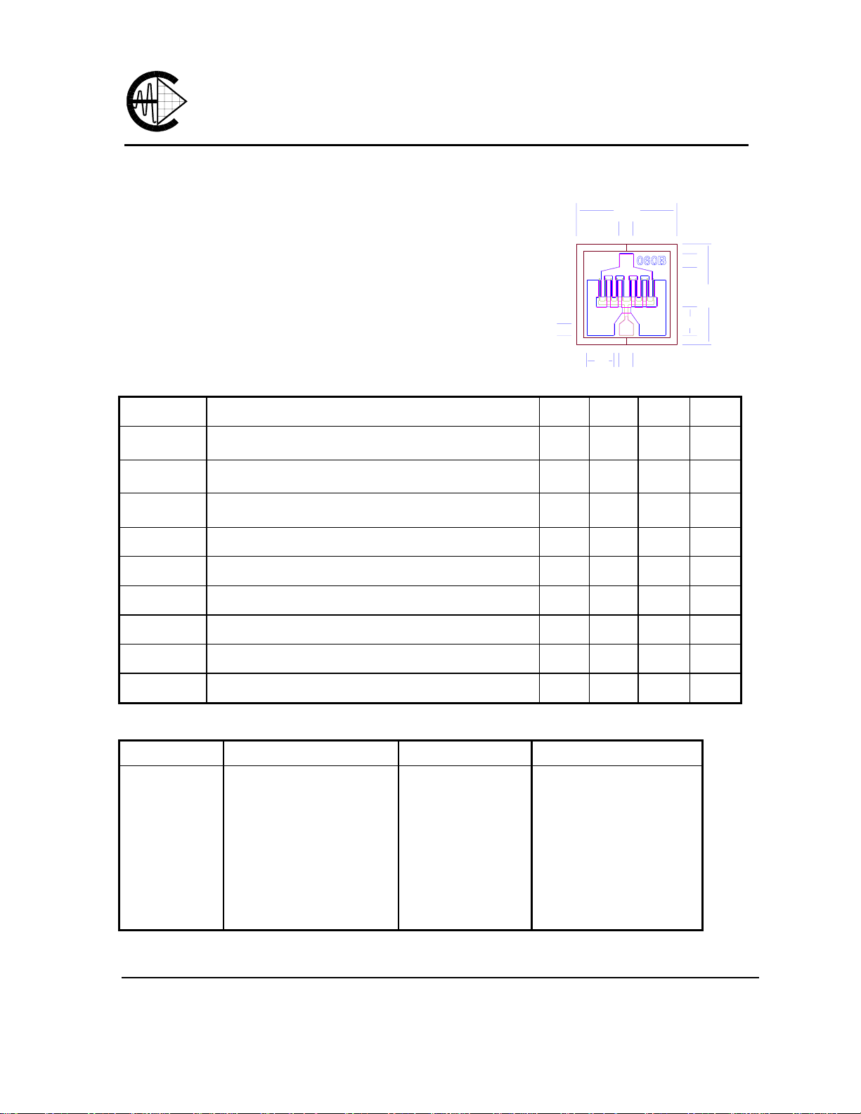
0.3 X 600 MICRON RECESSED “MUSHROOM” GATE
•
PASSIVATION
Si
•
3N4
ADVANCED EPITAXIAL DOPING PROFILE
•
PROVIDES HIGH POWER EFFICIENCY,
LINEARITY AND RELIABILITY
Idss SORTED IN 10mA PER BIN RANGE
•
ELECTRICAL CHARACTERISTICS (Ta = 25 OC)
SYMBOLS PARAMETERS/TEST CONDITIONS MIN TYP MAX UNIT
P
1dB
G
1dB
PAE
Idss
Output Power at 1dB Compression f=12GHz
Vds=10V, Ids=50% Idss f=18GHz
Gain at 1dB Compression f=12GHz
Vds=10V, Ids=50% Idss f=18GHz
Power Added Efficiency at 1dB Compression
Vds=10V, Idss=50% Idss f=12GHz
Saturated Drain Current Vds=3V, Vgs=0V 80 130 180 mA
350
50
D
S
40
Chip Thickness: 75 ± 13 microns
All Dimensions In Microns
23.0 25.0
25.0
9.0 10.5
8.0
35 %
S
G
5095
48
350
100
dBm
dB
Gm
Vp
BVgd
BVgs
Rth
Transconductance Vds=3V, Vgs=0V 50 70 mS
Pinch-off Voltage Vds=3V, Ids=1.5mA -2.5 -4.0 V
Drain Breakdown Voltage Igd=1.0mA -15 -20 V
Source Breakdown Voltage Igs=1.0mA -10 -17 V
Thermal Resistance (Au-Sn Eutectic Attach) 75
MAXIMUM RATINGS AT 25OC
SYMBOLS PARAMETERS ABSOLUTE1 CONTINUOUS2
Vds
Vgs
Ids
Igsf
Pin
Tch
Tstg
Pt
Note: 1. Exceeding any of the above ratings may result in permanent damage.
2. Exceeding any of the above ratings may reduce MTTF below design goals.
Drain-Source Vo ltage
Gate-Source Voltage
Drain Current
Forward Gate Current
Input Power
Channel Temperature
Storage Temperature
Total Power Dissipation
14V
-8V
Idss
15mA
23dBm
175oC
-65/175oC
1.8W
10V
-4.5V
150mA
2.5mA
@ 3dB Compression
150oC
-65/150oC
1.5W
Excelics Semiconductor, Inc., 2908 Scott Blvd., Santa Clara, CA 95054
Phone: (408) 970-8664 Fax: (408) 970-8998 Web Site: www.excelics.com
o
C/W

EFC060B
PRELIMINARY DATA SHEET
Low Distortion GaAs Power FET
S-PARAMETERS
10V, 1/2 Idss
Freq S11 S11 S21 S21 S12 S12 S22 S22
GHz Mag Ang Mag Ang Mag Ang Mag Ang
1.000 1.000 -22.2 4.497 162.6 0.022 75.2 0.568 -9.8
2.000 0.976 -43.5 4.274 147.4 0.042 65.1 0.553 -19.6
3.000 0.948 -64.1 3.993 132.7 0.059 53.7 0.524 -28.6
4.000 0.924 -82.9 3.676 119.0 0.072 43.1 0.492 -36.9
5.000 0.896 -100.8 3.334 105.8 0.080 34.2 0.446 -45.2
6.000 0.879 -115.2 3.005 94.5 0.086 26.7 0.418 -52.3
7.000 0.869 -127.1 2.720 84.8 0.089 20.4 0.398 -59.4
8.000 0.856 -136.5 2.487 75.7 0.091 15.0 0.380 -67.9
9.000 0.843 -145.4 2.291 67.0 0.092 9.0 0.374 -78.0
10.000 0.835 -154.1 2.119 58.4 0.092 4.2 0.384 -86.9
11.000 0.826 -162.9 1.955 50.4 0.092 0.3 0.395 -93.9
12.000 0.829 -170.1 1.826 42.7 0.091 -3.8 0.409 -100.1
13.000 0.825 -176.9 1.706 35.1 0.091 -7.5 0.415 -106.5
14.000 0.826 176.5 1.614 27.7 0.091 -10.6 0.426 -113.9
15.000 0.826 169.4 1.508 20.1 0.089 -15.0 0.435 -119.9
16.000 0.834 162.5 1.412 12.6 0.088 -17.6 0.439 -124.7
17.000 0.839 157.6 1.331 5.7 0.088 -20.3 0.432 -131.7
18.000 0.846 153.9 1.274 -1.0 0.089 -22.6 0.422 -141.5
19.000 0.844 150.1 1.218 -8.7 0.089 -25.8 0.422 -154.1
20.000 0.845 144.5 1.151 -16.6 0.089 -29.1 0.444 -166.5
21.000 0.851 134.1 1.055 -24.7 0.086 -31.9 0.476 -168.6
22.000 0.856 129.4 0.975 -31.0 0.084 -32.8 0.502 -177.0
23.000 0.866 126.8 0.907 -37.7 0.081 -34.5 0.543 175.0
24.000 0.869 124.1 0.841 -43.7 0.078 -34.4 0.574 168.2
25.000 0.874 121.9 0.775 -49.4 0.077 -34.9 0.618 162.2
26.000 0.876 118.6 0.711 -55.1 0.074 -32.9 0.660 158.1
Note: The data included 0.7 mils diameter Au bonding wires:
1 gate wires, 15 mils each; 1 drain wires, 20 mils each; 4 source wires, 7 mils each.
 Loading...