

Excelics EFA240D Datasheet
Excelics
EFA240D
DATA SHEET
Low Distortion GaAs Power FET
+31.0dBm TYPICAL OUTPUT POWER
•
18.5dB TYPICAL POWER GAIN AT 2GHz
•
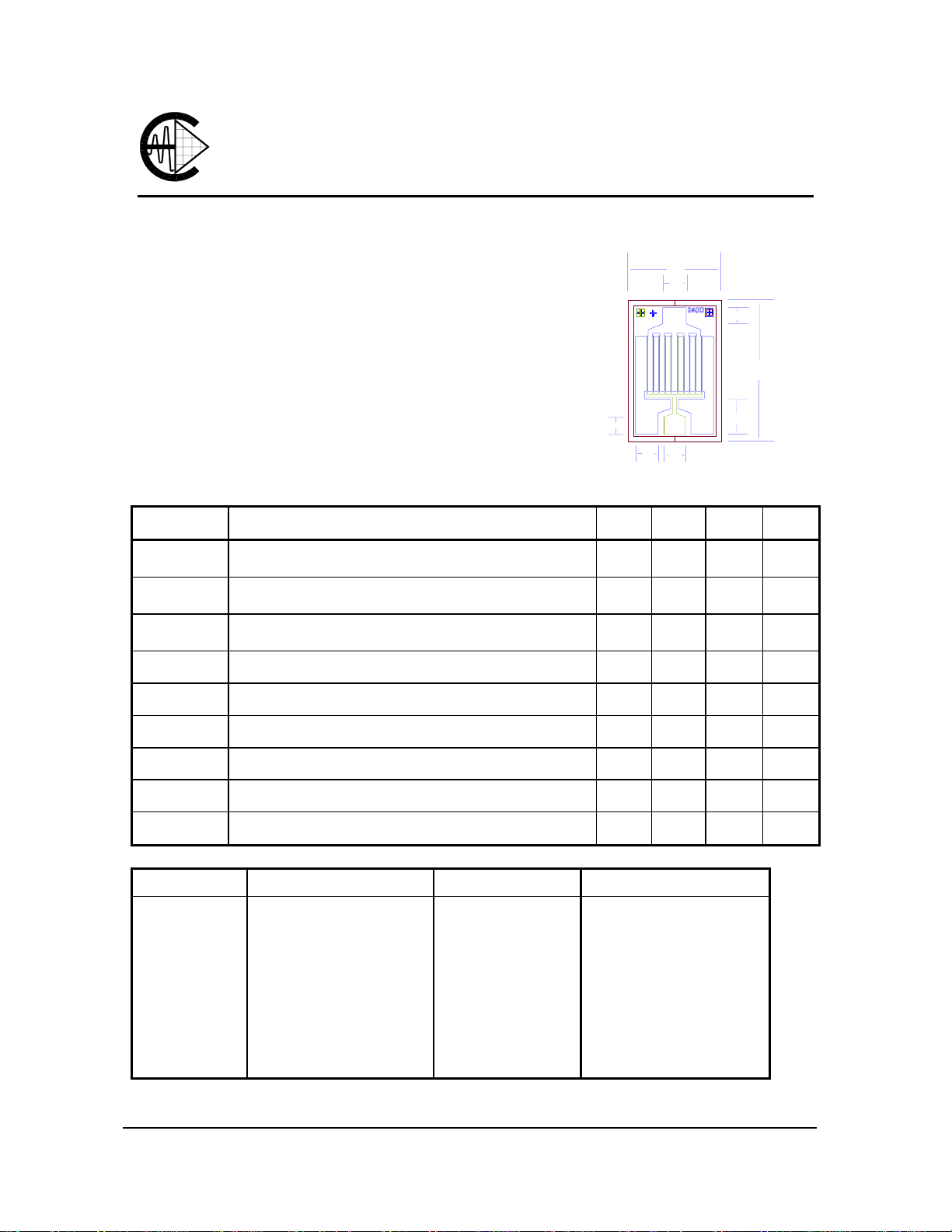
0.5 X 2400 MICRON RECESSED “MUSHROOM” GATE
•
PASSIVATION AND PLATED HEAT SINK
Si
•
3N4
ADVANCED EPITAXIAL DOPING PROFILE
•
PROVIDES HIGH POWER EFFICIENCY,
LINEARITY AND RELIABILITY
Idss SORTED IN 40mA PER BIN RANGE
•
75
ELECTRICAL CHARACTERISTICS (Ta = 25 OC)
SYMBOLS PARAMETERS/TEST CONDITIONS MIN TYP MAX UNIT
P
1dB
G
1dB
PAE
Output Power at 1dB Compression f= 2GHz
Vds=8V, Ids=50% Idss f= 4GHz
Gain at 1dB Compression f= 2GHz
Vds=8V, Ids=50% Idss f= 4GHz
Power Added Efficiency at 1dB Compression
Vds=8V, Ids=50% Idss f=2GHz
Chip Thickness: 75 ± 13 microns
All Dimensions In Microns
29.0 31.0
16.0 18.5
410
104
D
G
SS
100
94
31.0
13.5
45
Rev.1
72
620
155
dBm
dB
%
Idss
Gm
Vp
BVgd
BVgs
Rth
Saturated Drain Current Vds=3V, Vgs=0V 400 680 880 mA
Transconductance Vds=3V, Vgs=0V 280 360 mS
Pinch-off Voltage Vds=3V, Ids=6mA -2.0 -3.5 V
Drain Breakdown Voltage Igd=2.4mA -12 -15 V
Source Breakdown Voltage Igs=2.4mA -7 -14 V
Thermal Resistance (Au-Sn Eutectic Attach) 23
MAXIMUM RATINGS AT 25OC
SYMBOLS PARAMETERS ABSOLUTE1 CONTINUOUS2
Vds
Vgs
Ids
Igsf
Pin
Tch
Tstg
Pt
Note: 1. Exceeding any of the above ratings may result in permanent damage.
2. Exceeding any of the above ratings may reduce MTTF below design goals.
Drain-Source Vo ltage
Gate-Source Voltage
Drain Current
Forward Gate Current
Input Power
Channel Temperature
Storage Temperature
Total Power Dissipation
12V
-8V
Idss
60mA
29dBm
175oC
-65/175oC
6.0 W
8V
-4V
620mA
10mA
@ 3dB Compression
150oC
-65/150oC
5.0 W
Excelics Semiconductor, Inc., 2908 Scott Blvd., Santa Clara, CA 95054
Phone: (408) 970-8664 Fax: (408) 970-8998 Web Site: www.excelics.com
o
C/W

EFA240D
DATA SHEET
Low Distortion GaAs Power FET
S-PARAMETERS
8V, 1/2 Idss
FREQ --- S11 --- --- S21 --- --- S12 --- --- S22 --(GHz) MAG ANG MAG ANG MAG ANG MAG ANG
0.500 0.950 -75.6 11.303 136.8 0.027 53.1 0.195 -119.8
1.000 0.906 -116.5 7.670 113.0 0.036 35.5 0.264 -142.3
1.500 0.888 -138.2 5.566 99.1 0.040 27.9 0.290 -152.3
2.000 0.880 -151.5 4.317 89.4 0.041 24.4 0.303 -157.5
2.500 0.877 -160.7 3.510 81.6 0.042 22.9 0.312 -160.6
3.000 0.875 -167.7 2.952 74.9 0.043 22.5 0.321 -162.6
3.500 0.875 -173.3 2.544 68.8 0.043 22.6 0.329 -164.0
4.000 0.876 -178.1 2.233 63.2 0.044 23.2 0.338 -165.0
4.500 0.877 177.7 1.989 57.8 0.045 24.1 0.347 -165.9
5.000 0.879 173.9 1.792 52.7 0.046 25.1 0.356 -166.7
5.500 0.881 170.4 1.630 47.8 0.046 26.3 0.366 -167.5
6.000 0.883 167.1 1.493 43.0 0.047 27.5 0.377 -168.3
6.500 0.885 164.1 1.377 38.3 0.048 28.7 0.389 -169.1
7.000 0.887 161.1 1.276 33.7 0.050 30.0 0.400 -169.9
7.500 0.890 158.4 1.188 29.2 0.051 31.2 0.413 -170.8
8.000 0.893 155.7 1.109 24.8 0.052 32.3 0.426 -171.8
8.500 0.896 153.1 1.040 20.5 0.054 33.4 0.439 -172.9
9.000 0.899 150.6 0.977 16.2 0.056 34.4 0.453 -174.0
9.500 0.902 148.1 0.920 12.1 0.058 35.3 0.467 -175.2
10.000 0.905 145.7 0.867 8.0 0.060 36.0 0.481 -176.5
Note: The data included 0.7 mils diameter Au bonding wires:
1 gate wires, 20 mils each; 1 drain wires, 12 mils each; 4 source wires, 7 mils each.
Rev.1
 Loading...