

Page 1

Page 2

Page 3

Table of Contents
General Information . . . . . . . . . . . . . . . . . . . . . . . . . . . . . . . . . . . . . 1-1
To the New Owner . . . . . . . . . . . . . . . . . . . . . . . . . . . . . . . . . . . 1-1
Using This Manual . . . . . . . . . . . . . . . . . . . . . . . . . . . . . . . . . . . 1-1
Warranty Registration. . . . . . . . . . . . . . . . . . . . . . . . . . . . . . . . . 1-1
Parts and Service . . . . . . . . . . . . . . . . . . . . . . . . . . . . . . . . . . . . 1-1
Safety Precautions. . . . . . . . . . . . . . . . . . . . . . . . . . . . . . . . . . . . . . 2-1
Safe Operation and Service Precautions . . . . . . . . . . . . . . . . . . 2-1
Safety and Instruction Decals. . . . . . . . . . . . . . . . . . . . . . . . . . . 2-1
Assembly Instruction . . . . . . . . . . . . . . . . . . . . . . . . . . . . . . . . . . . . 3-1
Required Tools . . . . . . . . . . . . . . . . . . . . . . . . . . . . . . . . . . . . . . 3-1
Parts List . . . . . . . . . . . . . . . . . . . . . . . . . . . . . . . . . . . . . . . . . . 3-1
Assembly . . . . . . . . . . . . . . . . . . . . . . . . . . . . . . . . . . . . . . . . . . 3-1
Operation . . . . . . . . . . . . . . . . . . . . . . . . . . . . . . . . . . . . . . . . . . . . . 4-1
Vacuum Pickup and Collection. . . . . . . . . . . . . . . . . . . . . . . . . . 4-1
Unloading the Catcher Bags . . . . . . . . . . . . . . . . . . . . . . . . . . . 4-2
Transporting Mower With Catcher . . . . . . . . . . . . . . . . . . . . . . . 4-2
Converting To Side Discharge Mode . . . . . . . . . . . . . . . . . . . . . 4-2
Maintenance & Storage . . . . . . . . . . . . . . . . . . . . . . . . . . . . . . . . . . 5-1
Maintenance . . . . . . . . . . . . . . . . . . . . . . . . . . . . . . . . . . . . . . . 5-1
Storage. . . . . . . . . . . . . . . . . . . . . . . . . . . . . . . . . . . . . . . . . . . . 5-1
Two Bag Catcher Warranty Policy. . . . . . . . . . . . . . . . . . . . . . . . . . 6-1
Parts Manual . . . . . . . . . . . . . . . . . . . . . . . . . . . . . . . . . . . . . . . . . . 7-1
119649 toc-1 REV A
Page 4

REV A toc-2 119649
Page 5

GENERAL INFORMATION
To the New Owner
The purpose of this manual is to assist owners and operators
in maintaining and operating the Excel Two Bag Catcher. Please
read it carefully; information and instructions furnished can help
you achieve years of dependable performance.
Using This Manual
General operation, adjustment and maintenance guidance is
outlined for both the experienced and novice Excel user.
Operating conditions vary considerably and cannot all be
addressed individually. Through experience, however, operators
should find no difficulty in developing good operating skills
suitable to most conditions.
Directions used in this manual, for example RIGHT or LEFT,
refer to directions when in operator position and facing forward,
unless otherwise stated.
Photographs and illustrations used were current at the time of
printing, but subsequent production changes may cause your
machine to vary slightly in detail. Excel reserves the right to
redesign and change the machine as deemed necessary, without
notification. If a change has been made to your machine which
is not reflected in this operator’s manual, or the parts manual,
see your Excel Dealer for current information and parts.
Warranty Registration
Your Excel Dealer must register the unit on-line within ten
(10) days following date of purchase to validate your warranty
protection. As the new equipment owner, you should confirm
that your Excel Dealer has registered your catcher with Excel
Industries, Inc.
IMPORTANT: Any unauthorized modification, alteration,
or use of non-approved attachments voids the warranty and
releases Excel Industries, Inc. from any liability arising from
subsequent use of this equipment. Do not use or operate any
attachment not approved by Excel Industries, Inc.
Parts and Service
Use original Excel replacement parts only. These parts are
available through your local Excel Dealer. To obtain prompt,
efficient service, always provide the following information
when ordering parts:
1. Correct part description.
2. Correct part number.
3. Correct model number.
4. Correct serial number.
All warranty repair and service must be handled through an
authorized Excel Dealer. Arrangements should be made through
your local service center.
119649 1-1 REV A
Page 6

REV A 1-2 119649
Page 7

SAFETY PRECAUTIONS
This safety alert symbol is used to call attention to a message
intended to provide a reasonable degree of PERSONAL
SAFETY for operators and other persons during the normal
operation and servicing of this equipment.
DANGER
– denotes immediate hazards which WILL result in
severe personal injury or death.
WARNING
– denotes a hazard or unsafe practice which COULD
result in severe personal injury or death.
This manual uses two other words to highlight information.
IMPORTANT calls attention to special mechanical information
and NOTE emphasizes general information worthy of special
attention.
All operators and mechanics should read this manual, and be
instructed about safe operating and maintenance procedures.
Improper use or maintenance by the operator or owner can
result in injury. To reduce the potential for injury, comply with
these safety instructions and always pay attention to the safety
alert symbol “”, which means DANGER or WARNING “personal safety instructions.” Failure to comply with the
instructions may result in personal injury or death.
Incorrect usage of this attachment may result in severe
injury. Personnel operating and maintaining it should be
trained in the proper use and should read the manuals
completely and thoroughly before attempting to set-up,
operate, adjust, or service this mower.
Safe Operation and Service Precautions
All operator’s should be familiar with the mower’s opera-
tor’s manual, particularly the operational and safety
instructions contained in this manual.
Evaluate the terrain to determine what accessories and
attachments are needed to properly and safely perform
the job. Only use accessories and attachments approved
by the manufacturer.
Always stop on level ground, disengage deck clutch,
place steering control lever in the park brake position,
stop engine and remove ignition key before leaving operator’s seat for any reason including emptying the catcher
bags or unclogging the chute.
Always be aware of any obstructions, especially small
children, when backing or unloading the bags.
Always keep safety shields and covers in place, except
for servicing.
Never work on mower deck when the engine is running.
Never operate machine with the catcher lid in the raised
position except for unloading.
Never attempt high speed maneuvering in crowded or
congested areas.
Only use the weights, furnished with the catcher, when
using the catcher on this mower. Never operate the
mower with the catcher mounted and the weights not
installed. Make sure the weights are properly installed
and secured.
Always be aware that the catcher hangs off the rear of the
mower, thereby increasing the length of the mower. Use
caution when backing up or turning when the catcher is
mounted to the mower.
When the catcher is used, any rapid movement of the
control levers in either direction could result in a reaction
of the mower that can cause serious injury.
Always operate with complete catcher system, mulching
system or side discharge chute in place and in the lowest
position.
Never operate the mower with the catcher system
installed without the bags being properly installed and
the catcher lid in the lowered position.
Always keep clear of the mower blades and attachments
during their operation.
Turn off blades when not mowing.
Stop the engine before removing the grass catcher or
unclogging the discharge chute. Never clear the discharge
chute with the engine running. Turn off the engine and be
sure the blades have stopped before cleaning. Use a stick
to clear a plugged discharge area. Never use your hand!
Clean flammable material from machine. Prevent
fires by keeping engine compartment, exhaust area,
battery, fuel line, fuel tank and operator’s station
clean of accumulated trash, grass clippings, and other
debris. Always clean up spilled fuel and oil.
Grass collection system components are subject to wear,
damage and deterioration, which could expose moving
parts or allow objects to be thrown. Frequently check
components and replace with manufacturer’s recommended parts when necessary.
Never direct discharged material toward anyone. Avoid
discharging material against a wall or obstruction. Material may ricochet back towards the operator. Always disengage the blades and wait for them to stop before
crossing gravel drives, walks or roads.
Safety and Instruction Decals
The decals are designed to give the operator brief information
needed in the daily operation and service of the mower. These
decals are not intended to be used in place of this manual but
instead are to be used as an extension of this manual. These
119649 2-1 REV A
Page 8
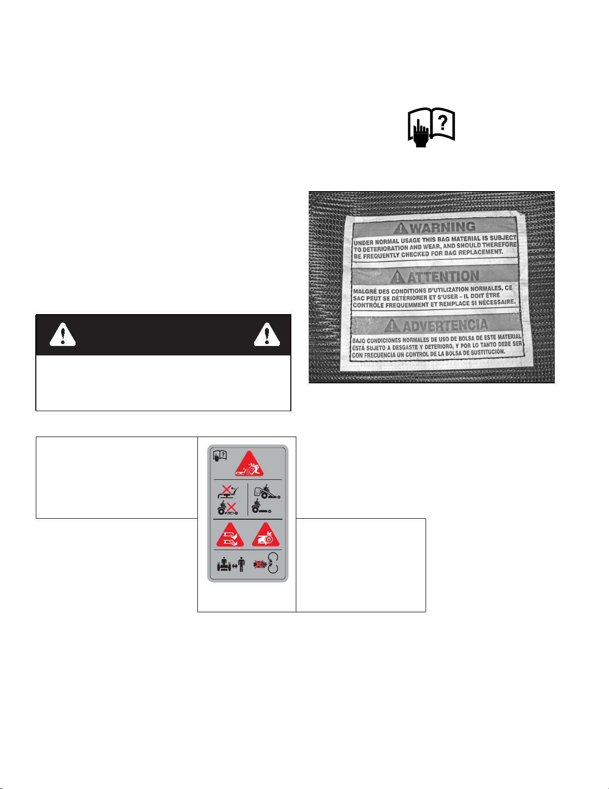
decals should not be removed or obliterated. Replace these
decals if they become unreadable.
• It is the owner’s responsibility to make certain that the
operators and mechanics read and understand this manual
and all decals before operating this mower.
• It is also the owner’s responsibility to make certain that
the operators and mechanics are qualified and physically
able individuals, properly trained in the operation of this
equipment.
• All operators and mechanics must become familiar with
the safe operation of the equipment, operator controls
and decals.
• Never let children or untrained people operate or service
the equipment. Local regulations may restrict the age of
the operator.
• The owner/user can prevent and is responsible for accidents or injuries occurring to themselves, other people or
property.
• The owner should also ensure that the operators/mechanics know that they are responsible for their own safety as
well as the safety of other persons within the vicinity.
Remember, the operator is responsible for accidents or
hazards occurring to other people or their property.
Refer to the mower’s operator’s manual for illustrations
showing the various safety decals that are located on the mower.
A brief explanation, for those requiring one, is shown to help the
operator understand the meanings of these decals.
• Read Operator’s Manual and Safety Warning Decals before
attempting to operate this machine.
WARNING
Specific safety warning decals are located on the equipment near the immediate areas of potential hazards. These
decals should not be removed or obliterated. Replace
them if they become non-readable.
WARNING:Thrown objects!
• Never operate the mower deck with side
deflector damaged, altered, removed or
in raised position, except when the
entire grass catcher attachment or
mulching system is being used.
Part Number 604221
• Under normal usage this bag material is subject to deteriora-
tion and wear, and should therefore be frequently checked for
bag replacement.
DANGER:
Rotating blades, pulleys & belts
• Keep shields and covers in
place while machine is in oper-
604221
ation
• Keep hands, feet and clothing
away from rotating pulleys and
belts.
REV A 2-2 119649
Page 9

ASSEMBLY INSTRUCTION
These instructions apply to the assembly of the Excel Two
Bag Catcher to an Excel 42” or 52" mower.
It is intended that these units be installed by trained Excel
service personnel. If additional assistance is required, contact
the Excel Customer Service Department.
Directions given in these instructions, for example left and
right, refer to direction while seated on the mower.
Before proceeding, read thru the following instructions to
familiarize yourself, while at the same time identify and
inventory kit parts supplied.
Unpack and inspect all parts. Notify carrier of any shipping
damages immediately.
Required Tools
The following is a list of the tools required to assemble the
catcher to the mower.
• Tape measure
• One 3/8” combination wrench or socket
• One 1/2” combination wrench or socket
• Two 9/16” combination wrench or socket
• Torque wrench (with 48 ft.-lb. range) with a 5/8” hex
socket
Parts List
PART NO. DESCRIPTION QTY.
N/A 2 BAG LID 1
N/A CATCHER CHUTE 1
N/A 1.6 BUSHEL BAG 2
603848 BLADE, 17.86"-CAT-F-CW (52” DECK) 1
793935 BLADE, 20.50"-CAT-F-CW (42” DECK) 1
117394 CATCHER FRAME 1
604387 UPPER CHUTE 1
604375 WEIGHT 2
604301 TIE ROD 2
117303 LS SUPPORT GUSSET 1
117304 RS SUPPORT GUSSET 1
117307 WEIGHT SUPPORT 1
117309 WEIGHT HOLD DOWN 1
117690 RS LEG MOUNT 1
117691 LS LEG MOUNT 1
792002 KNOB 5/16-18 X 3/4" 1
029629 CAP SCREW (CS) .375-16 X .75 HX FLK 8
016899 NUT .375-16 HX FLK ZNYC 8
086660 NUT .375-16 HX ZY NL 2
037887 CARRIAGE BOLT .312-18 X 1.00 2
768523 FLAT WASHER .343 X .687 X .051/.080H 2
058776 NUT .312-18 HX ZY NL 2
023036 HAIR PIN .148 X 2.69 ZN 2
604887 CE .375 x 3.00 WITH BALE 2
604806 PLASTIC CAP - TANK 1
000331 WIRE TIE 2
NOTE: Refer to the Parts Manual section (starting on page 7-
1) of this manual for more detailed parts information.
Assembly
NOTE: Refer to illustrated parts listings when assembling the
unit.
WARNING
Allow engine and muffler to cool before assembling the
catcher to the mower.
119649 3-1 REV A
Page 10

WARNING
WARNING
Never work under the machine or attachment unless it is
safely supported with jack stands. Make certain machine
is secure when it is raised and placed on the jack stands.
The jack stands should not allow the machine to move
when the engine is running and the drive wheels are rotating. Use only certified jack stands. Use only appropriate
jack stands, with a minimum weight rating of 2000
pounds to block the unit up. Use in pairs only. Follow the
instructions supplied with the vehicle stands.
1. Park the mower on a flat surface. Always place the deck
clutch switch in the disengaged position, place the
steering control levers in the park brake position, shut off
the ignition switch and remove the key from the switch.
Disconnect the negative battery cable.
2. Raise the front of the mower and deck up until the blades
can be accessed easily. Place the mower on jack stands
and do not allow the mower to move. Chock the rear
wheels.
WARNING
Mower blades are sharp and can cut. Wrap the blade(s) or
wear gloves and use extra caution when servicing them.
3. Remove the right side blade and replace it with the new
blade. The catcher is provided with one blade for a 42"
(two blade) mower and one blade for a 52" (three blade)
mower. Use the appropriate blade as indicated by the
label on the blade and discard the other blade. Figure 3-1
Torque blade bolt to 48 ft.-lbs. (65 N-m).
IMPORTANT: Only use a torque wrench when tightening and torquing the blade bolts.
NOTE: Retain the original blade as it will be re-used
when the mower is converted back to the side discharge
Failure to correctly torque the bolt may result in the loss
of the blade which can cause serious injury.
Blade
Existing
hardware
Torque to
48 ft.-lbs.
Figure 3-1
4. Remove the jack stands and lower the mower.
5. Attach the LS and RS leg mounts to the front of the
mower frame. Do not tighten the hardware at this time.
Figure 3-2
6. Attach the weight support to the LS and RS leg mounts.
Figure 3-2
7. Tighten the LS and RS leg mount hardware. Figure 3-2
8. Place the weights in the weight support and slide them
outward to allow the weight hold down to slide into place
between the two weights. Secure the weights in place
with the weight hold down using the hand knob to clamp
the weight hold down in place. Figure 3-2 & Figure 3-3
REV A 3-2 119649
Page 11

9.
Weight hold down
Weights
Nut .375-16 HXFLK
RH Leg mount
Weight hold down
Cap screw
.375-16 x .75
LH Leg mount
Flat washer .343”
Nut .312-18 NL
Weight support
Knob
Carriage bolt
.312-18 x 1.00
Figure 3-2
LH Leg mount
RH Leg mount
Figure 3-3
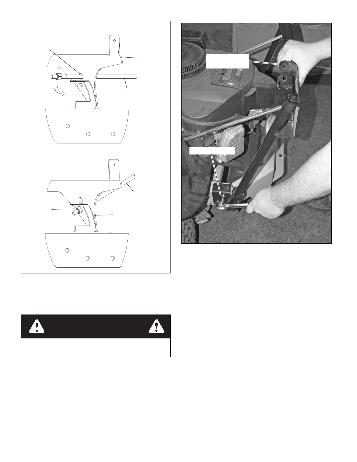
10. Remove the tie rods from the catcher frame. The tie rods
are embedded with the catcher frame for shipping
purposes only.
11. Attach the catcher frame to the rear of the mower. Do not
tighten the mounting bolts at this time. Figure 3-4
Weight
Knob
Weight support
NOTE: Some mower models have a taller rear engine
guard. If a catcher is being attached to one of these models, it will be necessary to remove the engine guard. Fig-
ure 3-5
119649 3-3 REV A
Page 12

Catcher frame
Cap Screw .375-16 x .75
Nut .375-16 HXFLK
Nut .375-16
HXFLK
Hair pin
Mower
frame
Tie rod
Nut .375-16 NYLK
View A
Keyhole
Fender
support
bracket
Support
gusset LH
Support
gusset LH
Refer to
View A
Support
gusset RH
Figure 3-4
Tall engine
guard
Figure 3-5
12. Raise the seat platform.
13. Unbolt the mower’s fenders from the mower frame.
There are four bolts per fender that will need to be
removed. Figure 3-6
This allows the fenders to be moved to provide access to
the mower frame. It is not necessary to remove the
fenders from the mower.
Cap Screw .375-16 x .75
NOTE: It will be necessary to unscrew the fuel cap from
the fuel tank fill neck and slide the plastic cap over the fill
neck opening. The plastic cap will slide over the fuel
cap’s tether line. This will allow the left fender to move
enough to allow access to the hole in the mower frame.
Figure 3-7
NOTE: It is not necessary to remove the control panel
from the right fender. There should be sufficient access to
the frame with the fender loose.
WARNING
When performing this step heed the warnings listed
below:
• Do not smoke while the fuel cap is not properly
secured to the fuel tank fill neck. Extinguish all cigarettes, cigars, pipes and other sources of ignition.
• Use extreme care when handling gasoline which is
extremely flammable and vapors are explosive. A
fire or explosion from fuel can burn you and others
and can damage property.
• Do not remove the fuel cap with engine running
or while engine is hot. Clean up any fuel spills.
• If fuel is spilled on clothing, change clothing immediately.
REV A 3-4 119649
Page 13

Fender
Remove these bolts
Fill neck
Remove
this bolt
Fender
Figure 3-6
14. Attach the support gussets to the mower frame. The slots
in the support gussets must align with the keyhole slots in
the fender support bracket. Assemble the hardware as
shown with the cap screw inserted from the bottom.
Figure 3-4 View A
IMPORTANT: Be sure not to cut or pinch the fuel line
when installing gussets.
15. Thread a .375-16 nylon locking nut onto each of the tie
rods to the dimension shown in Figure 3-4 & Figure 3-8
Tie rod
Nut .375-16 NYLK
Fuel cap
Fuel cap
Tether
Plastic cap
Tether
1” ± 1/16”
(19mm)
Figure 3-8
16. Insert one tie rod through the key hole slot in the fender
support bracket and into the slot in the support gusset.
Make sure the nut on the tie rod is inserted through the
slot in the support gusset. Figure 3-4 & Figure 3-9
The nut end of the tie rod can be easily inserted through
the upper end of the slot if positioned horizontally then
angled upwards after the nut clears the support gusset.
Figure 3-4 & Figure 3-9
IMPORTANT: Be certain that the nut does not catch or
pinch the vapor line.
Then, insert the tie rod through the proper hole in the
catcher frame and secure with a hair pin. Figure 3-4
Repeat for the other side.
17. Push down on the catcher frame and tighten the lower
frame bolts. Pushing down on the catcher frame while
tightening these bolts will provide the correct tension on
the tie rods. Figure 3-10
18. Secure the vapor lines using the zip ties as shown. You
must secure the vapor lines to prevent them from rubbing
Plastic cap
Fuel tank
Fender
Figure 3-7
on the tie rods. Remove the excess zip tie. Figure 3-11 &
Figure 3-12
IMPORTANT: Make sure the vapor line does not
become pinched and retains its original routing as it
comes out of the top of the fuel tank. Figure 3-13
119649 3-5 REV A
Page 14
Insert the tie rod through the keyhole as shown.
Keyhole
Then, angle the tie rod to secure the
nut against the support gussets.
Nut
Mower
frame
Tie rod
Tie rod
Support gusset
Push the catcher
frame down here
Tighten frame bolts
Figure 3-9
19. Re-attach the fenders to the mower frame. Do not
overtighten the mounting hardware. Figure 3-6
20. Remove the plastic cap from the fill neck opening and
screw the fuel cap onto the fill neck. Figure 3-7
WARNING
Never operate the mower without the fuel cap threaded
tightly onto the fill neck.
21. Use a hammer and screwdriver to bend the tabs on the
deck inward enough to allow the steel hooks of the elastic
latch on the outlet tube to be inserted into the slot. Figure
3-14, Figure 3-15 & Figure 3-16
42” deck – There are two tab locations.
52” deck – There is one tab located at the rear side of the
deck.
22. Raise the deck discharge chute to the full up position
(90o) and slide the outlet tube into position.
Figure 3-10
It will be necessary to force the discharge chute to the 90
position. The chute will contact the mower fender before
the 90o position is attained. Push on the discharge chute
until the chute is open enough to allow the tab of the
outlet tube to be inserted into the slot in the discharge
chute bracket of the deck. The downward spring force of
the discharge chute helps to secure the outlet tube to the
deck by locking the bump on the outlet tube with the
cams of the discharge chute. Figure 3-17 & Figure 3-18
Secure the outlet tube in place with the elastic latches.
Figure 3-14
23. Slide the end of the transfer tube into the opening in the
catcher lid. Figure 3-19
24. Attach the transfer tube to the outlet tube by aligning the
slot on the transfer tube with the knob on the outlet tube
and hooking the elastic latch through the loop of the
transfer tube. Figure 3-20 & Figure 3-21
25. Place the bags on the catcher frame by inserting the bag
frame hook into the catcher frame slot. Figure 3-22
26. Attach the catcher lid to the catcher frame using the CE
.375 x 3.00 with bale pins. Close the catcher lid. Figure 323
NOTE: It is easier for two people to attach the catcher
lid to the catcher frame than it is for one person.
o
REV A 3-6 119649
Page 15

Support
gusset
Vent line
Support
gusset
Tie rod & nut
Tie rod & nut
Vent line
Left side vent line - original routing
Left side vent line - new routing
Zip tie
Tie vapor line to bracket enough to pull
vapor line away from the tie rod threads.
Tie rod & nut
Vent line
Fuel line
Figure 3-11
27. Reconnect the negative battery cable.
WARNING
Bracket
Throttle
cable
Right side vent line - original routing
Zip tie
Vent line
Tie rod & nut
Right side vent line - new routing
Figure 3-12
Vent line
Do not operate deck without discharge chute or complete
catcher system in place.
Zip tie
Fuel line
Figure 3-13
119649 3-7 REV A
Page 16

Tab
Discharge chute
Discharge
chute
Outlet
tube
Elastic Latch
Figure 3-14
Tab 42”
only
52” deck only
Elastic
Latch
Discharge
chute
Front anti-scalp
wheel backet
Discharge chute
bracket slot
Outlet tube tab
Outlet tube tab not installed correctly
Figure 3-17
Outlet tube tab installed correctly
Discharge chute
Ridge on outlet tube
Outlet tube tab
Discharge chute
bracket slot
Cam of discharge chute
Hammer
Screwdriver
Tab
Figure 3-15
Figure 3-16
Tab
Figure 3-18
Catcher
lid
Transfer
tube
Elastic
Latch
Outlet
tube
Figure 3-19
REV A 3-8 119649
Page 17

Transfer
tube slot
Outlet tube knob
Elastic latch
Transfer
tube
Elastic
latch
Bag
Bag
frame
hook
Figure 3-20
Catcher
frame
Outlet
tube
Figure 3-22
Figure 3-21
119649 3-9 REV A
Page 18

Catcher lid
CE .375 x 3.00
with bale pin
CE .375 x 3.00
with bale pin
Figure 3-23
REV A 3-10 119649
Page 19

OPERATION
Vacuum Pickup and Collection
Follow normal mower start-up and operating procedures as
outlined in the mower operator’s manual. Whenever the deck
clutch switch is engaged there will be debris moving through the
catcher system.
The following list contains useful information when using the
catcher:
• When catching, use the left side of the mower for trimming to prevent damage to the discharge chute and outlet
tube.
• Catching with the cutting height set too low may prevent
adequate air movement under the deck. This will cause
clogging of the catching system.
• During peak growing times it may be necessary to cut the
grass more often. If the grass is too long it may need to be
cut twice. First, mow the grass with the cutting height set
at a high setting to cut off the upper parts of the grass.
Next, lower the cutting height to the preferred finished
cut height and mow the area again. This will help reduce
clogging.
• To help reduce clogging mow by slightly overlapping the
previously cut area.
• Proceed to mow in the normal manner with the engine
throttle set to the “FAST” position. Control the mower’s
ground speed by using the steering control levers. In tall
and/or wet grass the high engine speed and slower
ground speed will help prevent clogging.
• When catching on slopes mow going downhill when possible. It is necessary to reduce ground speed when operating on a slope.
• If debris begins to blow out in front of the outlet tube or a
trail of debris is visible along the right edge of the cutting
path, either the catcher is full or the outlet tube is
clogged.
• As you mow visually check how full the bags are, when
the right bag looks full move the deck clutch switch to
the disengaged position and drive the machine to the
unloading area.
• It is best that the bags be unloaded before the discharge
chute and tube areas become clogged. If clogging occurs,
it will be necessary to clean the discharge chute and tube
areas of all material before starting to mow again.
• When the grass is wet it may be necessary to mow it first
in the side discharge mode. Then, after the clippings have
dried, go back over the area with the catcher installed and
pickup the clippings.
• To minimize clogging, reduce your mowing speed as
necessary or wait until there is less moisture in the grass.
WARNING
Make certain the engine is turned off, the steering control
levers are in the park brake position and the ignition key
is removed from the ignition switch. Be sure blades have
stopped before cleaning the discharge chute and transfer
tube areas.
WARNING
WARNING
Remember, as the bags fill more weight is added to the
back of the mower. Any rapid movement of the control
levers in either direction could result in a reaction of the
mower that can cause serious injury.
• Do not stop or start suddenly when mowing on
slopes. Avoid uphill starts.
• Disengage the blades if you stop the mower when
going uphill and proceed to back off the slope
slowly.
• Maintain an even mowing speed when operating on
slopes.
• Do not stop on a slope.
• Never operate the mower with the catcher attached
on a slope without the front weights installed and
securely fastened.
Never place hands or feet into the discharge area. The
mower blade is relatively close to the housing and will
cause severe injury. Use a probe to clean debris from the
catcher outlet tube.
WARNING
Never engage the mower deck unless the catcher transfer
tube is secured in place, with the elastic strap, on the outlet tube and is inserted into the catcher lid. Figure 4-1
119649 4-1 REV A
Page 20

Catcher
Outlet
tube
Catcher lid
lid
Bag frame
handle
Transfer
tube
Figure 4-1
Unloading the Catcher Bags
WARNING
Park the unit on a level surface, disengage the deck clutch
switch, place the steering control levers in the park brake
position and shut the engine off. Make certain the deck
clutch switch is in the disengaged position before unloading.
Get off the mower. Raise the catcher lid and remove the bag
by lifting the bag frame at the rear of the bag and the bag frame
handle. Proceed to dump the bag. Figure 4-2
Return the bags to the catcher frame and close the catcher lid.
Figure 4-2
Transporting Mower With Catcher
When transporting the mower, with the catcher attached, to
another location on an open trailer or vehicle, the catcher lid,
bags, and tubes must be removed and secured in the transporting
vehicle to prevent them from being blown off.
Bag frame
Bag
Catcher bags
Figure 4-2
Catcher
frame
Figure 4-3
Converting To Side Discharge Mode
Convert the mower back to the side discharge mode when
catching is not desired.
When converting to side discharge mode it will be necessary
to remove the bags, tubes, catcher lid, and weights from the
mower. The weight mount and catcher frame can remain in
place on the mower.
When operating in side discharge mode, failure to remove
the front weights can make the mower unstable, in some
conditions, which could lead to loss of control.
When converting to the side discharge mode it is necessary to
remove the right hand (catching) blade from the mower. Replace
WARNING
it with the proper side discharge blade. Torque blade bolt to 48
ft.-lbs. (65 N-m).
REV A 4-2 119649
Page 21

IMPORTANT: Only use a torque wrench when tightening
and torquing the blade bolts.
IMPORTANT: Make certain the discharge chute is lowered
to the mowing position before mowing.
WARNING
Failure to correctly torque the bolt may result in the loss
of the blade which can cause serious injury.
WARNING
Always operate with complete catcher system, mulching
system or side discharge chute in place and in the lowest
position.
119649 4-3 REV A
Page 22

REV A 4-4 119649
Page 23

MAINTENANCE & STORAGE
Maintenance
WARNING
Never work on the mower deck when the engine is running.
WARNING
Clean flammable material from machine. Prevent
fires by keeping the engine compartment, top of deck,
exhaust area, battery, fuel line, fuel tank and operator’s station clean of accumulated trash, grass clippings, and other debris. Always clean up spilled fuel
and oil.
Inspect the catcher after the initial use of the unit and every
month thereafter.
• Check for damaged or worn parts. Replace or repair all
damaged parts before operating with the catcher again.
• Check for loose hardware. Tighten any hardware that is
loose.
• Inspect the tie straps and replace any that are missing,
damaged or beginning to show signs of wear.
• Inspect and replace the bags if any deterioration has
occurred.
WARNING
Prevent objects being thrown and the accumulation of
grass clippings and other debris in engine compartment by NEVER operating the mower deck unless:
• Both bags are installed.
• Catcher lid is lowered.
• Outlet tube is in place and secured on the discharge chute outlet and deck. Figure 5-1
• Transfer tube is secured in place, with the elastic
strap, on the outlet tube and is inserted into the
catcher lid. Figure 5-1
To service the outlet tube and transfer tube, remove the tubes
from the unit. The tubes can be cleaned by using soapy water
and washing the inside of the tubes with a pressure washer.
Rinse with water.
To clean the bags, hand wash with soap and water; rinse with
clean water.
Catcher
lid
WARNING
Severe injury can occur to the operator and/or bystanders
or property damage may occur as the result of flying
debris or thrown objects due to damaged bags.
• Check bags for any signs of damage such as tears,
holes, wear or any deterioration.
• If a bag is found to be defective in any way, replace
it with a new bag that is supplied by Excel Industries, Inc.
The outlet tube and transfer tube should be kept clean and free
of any accumulation of matted clippings or other obstructions.
Transfer
tube
Outlet
tube
Figure 5-1
Storage
When your mower is to set idle for a period of time, scrape
and remove the matted grass material from inside the hood and
clean the bags.
Check for loose or missing hardware, tighten or replace. Also
check for badly worn or damaged parts, consider replacing them
at this time. Touch up chipped paint areas, your dealer has
aerosol spray paint available.
119649 5-1 REV A
Page 24

REV A 5-2 119649
Page 25

Two Bag Catcher Warranty Policy
Excel Industries, Inc. makes the following warranty to the
original purchaser only:
a. Excel Industries, Inc. Attachments and Accessories
are warranted for one (1) year (parts and labor)
from date of delivery on all materials and
workmanship.
If the Purchaser discovers within this warranty period
a defect in materials or workmanship:
He must promptly notify an authorized Excel
Industries, Inc. dealer of the defect. In no event
General Information
Who Must Perform The Warranty Service
All warranty service will be performed by dealers
authorized by Excel Industries, Inc.. Service calls and/or
transportation expense of the product to and from the
authorized dealer, for warranty work, will be paid by the
owner of the product. For warranty service contact an
authorized dealer.
What Is Not Covered By This Warranty
Excel Industries, Inc. does not warranty:
Repairs made by unauthorized persons.
Damage caused by use of the Excel Industries, Inc.
turf equipment for purposes other than those for
which it was designed.
Damages caused by disasters such as fire, flood,
wind, and lightning.
Damages caused by neglect, abuse, abnormal use,
improper or unreasonable use, accident, negligence
or misuse.
Repairs or replacement resulting from the use of
unauthorized parts, accessories or attachments.
Damage caused by foam filled or solid filled tires.
Repairs or replacement as the result of alterations
or modifications.
Excel Industries, Inc. turf equipment which has the
serial number removed or made illegible.
Depreciation or damage caused by normal wear,
lack of reasonable and proper maintenance, failure
to follow the product’s operator’s manual operating, maintenance and adjustment instructions or
other operational instructions provided by Excel
Industries, Inc.
Normal maintenance parts and service including,
but not limited to, lubricants, belts, blades, blade
sharpening, or bearings.
shall such notification be received by an authorized
Excel Industries, Inc. dealer later than thirteen
(13) months from date of delivery.
Within a reasonable time after such notification,
Excel Industries, Inc. will correct any defect in
material or workmanship on the Excel Industries,
Inc. turf equipment, by repairing or replacing
part(s) with either new or used replacement parts.
Such repair, including parts and labor shall be at
the expense of Excel Industries, Inc., and,
Disclaimer Of Warranty
The foregoing warranties are in lieu of all other warranties,
expressed or implied, including but not limited to the implied
warranties of merchantability and fitness for a particular
purpose. However, if the Excel Industries, Inc. turf equipment
is purchased as a consumer product, any implied warranty of
merchantability or fitness for a particular purpose is limited to
the duration of this limited warranty. Some states do not allow
limitations on how long an implied warranty lasts, so the
above limitation may not apply to you. This warranty gives
you specific legal rights, and you may also have other rights
which vary from state to state.
Limitations Of Warranties
In no case shall Excel Industries, Inc., be liable for any
special, incidental, or consequential damages based upon
breach of warranty, breach of contract, negligence, strict
liability in tort, or any other legal theory.
Such damages include, but are not limited to:
Loss of profits
Loss of savings or revenue
Loss of use of Excel Industries, Inc. turf equipment
or any associated equipment
Cost of capital
Cost of any substitute equipment, facilities, ser-
vices or downtime
The claims of third parties including customers,
and injury to property
Some states do not allow the exclusion or limitation of
incidental or consequential damages, so the above limitation or
exclusion may not apply to you.
No Other Warranties
Unless modified in writing, signed by both parties, and
approved by the President of Excel Industries, Inc., this
agreement is understood to be the complete and exclusive
agreement between the parties, superseding all prior
119649 6-1 REV A
Page 26

agreements, oral or written, and all other communications
between the parties relating to the subject matter of this
agreement. No employee of Excel Industries, Inc., or any other
party is authorized to make any warranty in addition to those
made in this agreement.
Allocation Of Risks
This agreement allocates the risks of product failure
between Excel Industries, Inc. and the purchaser. This
allocation is recognized by both parties and is reflected in the
price of the goods.
Owner’s Responsibility
You must maintain your Excel Industries, Inc. Product
following the maintenance procedures described in your
operator's manual. Such routine maintenance, whether
performed by a dealer or by you, is at your expense.
This machine like any other powered equipment is
potentially dangerous unless properly operated. Any
operator must be cautious and keep safety in mind at all times.
Any operator, prior to using the Excel Industries, Inc. turf
equipment, should thoroughly familiarize himself with the
operator's manual regarding operation and safety of the
machine, as well as all safety warnings on the machine itself.
Warranty Registration
Excel Industries, Inc. Dealers must register the
unit on-line at https://excel.warrantysmart.ari-
net.com within ten (10) days following date of
purchase.
REV A 6-2 119649
Page 27

Parts Manual
Catcher Frame. . . . . . . . . . . . . . . . . . . . . . . . . . . . . . . . . . . . . . . . . . 7-2
Catcher Lid—552396. . . . . . . . . . . . . . . . . . . . . . . . . . . . . . . . . . . . . 7-4
Catcher Chute & Blades . . . . . . . . . . . . . . . . . . . . . . . . . . . . . . . . . . 7-6
Catcher Bag Assembly—552460. . . . . . . . . . . . . . . . . . . . . . . . . . . . 7-8
119649 7-1 REV A
Page 28

Catcher Frame
CATCHER LID
1
2
1
4
2
3
5
4
6
6
5
7
6
8
9
5
10
11
11
12
6
5
REV A 7-2 119649
18
14
15
13
17
14
15
16
Page 29

Catcher Frame
INDEX NO. PART NO. QTY. DESCRIPTION
1 604887 2 CE .375 X 3.00 WITH BALE
2 023036 2 HP .148 X 2.69 ZN
3 117394 1 CATCHER FRAME
4 604301 2 TIE ROD
5 029629 8 CS .375-16 X .75 HX FLK
6 016899 8 NT .375-16 HX FLK ZNYC
7 117303 1 LS SUPPORT GUSSET
8 086660 2 NT .375-16 NL G5
9 117304 1 RS SUPPORT GUSSET
10 117309 1 WEIGHT HOLD DOWN
11 604375 2 WEIGHT
12 117691 1 LS LEG MOUNT
13 037887 2 CB .312-18 X 1.00 FULL ZN
14 768523 2 FW .343 X .687 X .051/.080H
15 058776 2 NT .312-18 HX NL G5
16 792002 1 KNOB 5/16-18 X 3/4"
17 117307 1 WEIGHT SUPPORT
18 117690 1 RS LEG MOUNT
NOTES:
119649 7-3 REV A
Page 30

Catcher Lid—552396
1
2
8
4
4
6
8
9
10
10
4
7
3
8
5
4
11
10
10
12
REV A 7-4 119649
Page 31

Catcher Lid—552396
INDEX NO. PART NO. QTY. DESCRIPTION
1 603398 6 RIVET
2 117501 1 CATCHER INLET
3 604394 1 INLET SEAL
4 603400 13 FW .188 X .50 X .060
5 552396 1 CATCHER LID (COMPLETE ASSEMBLY)
6 117678 1 VENT MOUNT BRACKET
7 117584 1 BAG DIVIDER
8 604805 7 BLIND RIVET
9 064329 3 CS .250-20 X .625 HX G5
10 768515 6 FW .281 X .625 X .051/.080 HD ZN/YL
11 118562 1 DEBRIS GUIDE
12 068551 3 NT .250-20 HX ZY NL
NOTES:
119649 7-5 REV A
Page 32

Catcher Chute & Blades
3
4
5
1
2
4
6
3
4
5
4
5
6
3
4
4
7
EXISTING
HARDARE
REV A 7-6 119649
1
Page 33

Catcher Chute & Blades
INDEX NO. PART NO. QTY. DESCRIPTION
1 604387 1 UPPER CHUTE
2 604371 1 OUTLET TUBE
3 068551 3 NT .250-20 HX ZY NL
4 768515 6 FW .281 X .625 X .051/.080H
5 604475 3 BUNGEE LATCH
6 704916 3 CS .250-20 X 1.25 HX G5
7 793935 1 BLADE, 20.50"-CAT-F-CW (42" DECK)
8 603848 1 BLADE, 17.86"-CAT-F-CW (52" DECK)
1. Torque to 48 ft-lbs.
NOTES:
119649 7-7 REV A
Page 34

Catcher Bag Assembly—552460
1
4
5
6
2
3
7
REV A 7-8 119649
Page 35

Catcher Bag Assembly—552460
INDEX NO. PART NO. QTY. DESCRIPTION
1 117393 1 BAG SUPPORT
2 117390 1 BAG CATCH
3 602827 1 CB .312-18 X 1.25 ZNYC
4 117401 1 CLAMP BRACKET
5 768523 1 FW .343 X .687 X .051/.080H
6 058776 1 NT .312-18 HX ZY NL
7 552460 1 CATCHER BAG ASSEMBLY (BAG INCL. ITEMS 1–6)
NOTES:
119649 7-9 REV A
Page 36

REV A 7-10 119649
Page 37

INDEX
PAGE PAGE
Assembly .................................................................3-1
Converting To Side Discharge Mode .....................4-2
Maintenance
Parts and Service
............................................................5-1
....................................................1-1
Parts List ..................................................................3-1
Required Tools
Safe Operation and Service Precautions
........................................................3-1
..............2-1
Safety and Instruction Decals ............................... 2-1
Storage .................................................................... 5-1
To the New Owner
Transporting Mower With Catcher Attached
................................................. 1-1
........ 4-2
Unloading the Catcher Bags ................................. 4-2
Vacuum Pickup and Collection
Warranty registration
............................................. 1-1
............................. 4-1
119649 i-1 REV A
Page 38

REV A i-2 119649
Page 39

Page 40

 Loading...