

Page 1
Enbeam Fibre Optic Splice Closure
208-504 Installation Manual
208-504 is a multifunctional bre splice equipment which is designed for bre connection, branching and
terminal connection. This FOSC has three single bre ports; one bre port for uncut cable usage, one testing port
(Φ6mm) and four pigtail outlets (Φ2.0mm). It is suitable for wall-mounting, aerial, pole-mounting, especially used
for FTTH bre distribution. We are always in pursue of doing research and developing the telecommunication
connection equipment. Our FOSC is your reliable choice to guarantee the quality of information transform.
1. Specication
Size H×W×D (mm) 300×220×100 Max capacity (single bre) 60
Weight (kg) 2.4~2.7 Airproof style Mechanical
Entrances 5
Suitable cable diameter Ф8~ф15
Number of trays 5
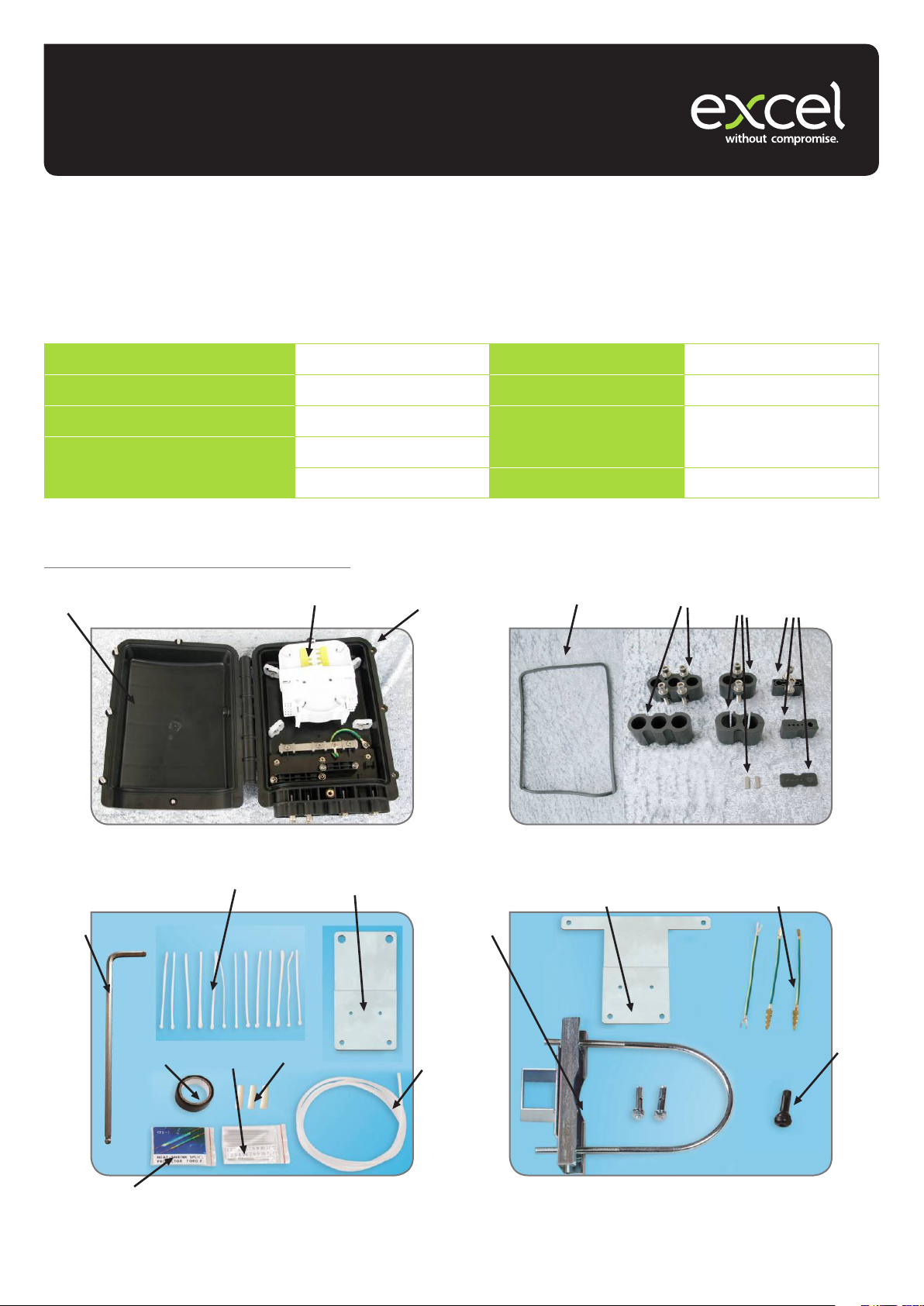
2. Internal Structure and Components
2.1 Pictures of bre closure and its components:
3
2
Capacity of tray 12
1
4
6
5
7
15
9
12
8
11
14
10
1718
19
16
13
Page 2

2.2 Accessories
2.2.1 Main components
Number Name Quantity Marks
1 Base 1 Fixing internal structure
2 Fibre splice tray 1 set Fibre splice and storage
3 Cover 1
4 Seal ring 1 Fixing cover and base
5 Two-hole sealing xtures 1 Using in the uncut bre sealing
6 Three-hole bre cable xtures 1 Fibre cable sealing
7 Sealed tray bracket 1 set Φ2.0pigtail, Φ6 testing pigtail sealed
2.2.2 Accessories
Number Name Quantity Application
8 Splice protective sleeve According to standard
tting
9 Nylon tie 16 pieces Fixing bres with Protective jacket
10 Wall-mounting installation
xtures
11 Data paper 1 piece Fibre labeling
12 Insulation tape 1 piece
13 Protective tube 1 piece Fibre protection
14 Plastic block 3 For ports when not used
15 Hexagonal spanner 1 Fixing the bolt
1 set Fixing FOSC
Fibre fusion and protection
2.2.3 Optional Accessories
Number Name Quantity Application
16 Valve 1 set Test pressure
17 Grounding xing set 1 set Ground-mounting
18 Aerial installation xtures 1 set For installation of the closure aerially
19 Pole installation xtures 1 set For mounting the closure on the pole
3. Installation Flow Chart
Open the closure
Splice bres
Determine the length of bre cable
to be xed and stripped inside
Put the sealing parts into the bottom of
Strip o protective coats
Close the cover, screw the bolt
the closure
tightly
Fix reinforced core and bre
Introduce the bre into the splice tray
Install the closure with loop
Page 3
4. Direction
4.1 Preparation
4.1.1 Please check the structure and type of the cable before installation. Dierent types of bre can’t be spliced together.
4.1.2 Ensure all seals are mounted correctly and take care not to over tighten.
4.1.3 Keep the working place free from moisture and dust. Don’t give any impact on the cables and don’t bent or entwine cables.
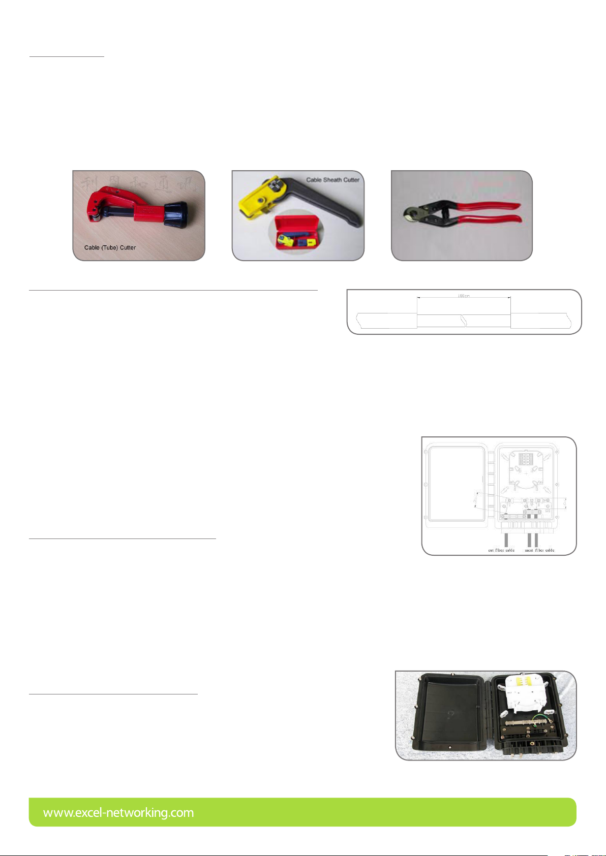
4.1.4 Use appropriate tools according to the approved standard of bre optic splicing in your region when remove the jacket of
cables and assemble the closure.
Tools as following:
4.2 Remove the jacket of cables for uncut bre installation
4.2.1 Mark the point on the cable, the length of stripping is about 180cm.
4.2.2 Remove the jacket from the marked point with a sheath stripper
NOTE: 1. Be sure not to damage bre
2. Do not use any damaged cable
3. While removing the cable sheath, please do not cut, twist or damage cable jacket. Reserve enough length to
ensure repair and maintenance in case of any accidents.
4.2.3 Cut o the extra reinforced core about 4cm from the removing point on the sheath.
4.3 Removal of the single cable jacket
4.3.1 Mark the point on the cable; the length of stripping is about 180cm from the end.
4.3.2 Remove the jacket
NOTE: 1. Be sure not to damage bre
2. Do not use any damaged cable
3. While removing the cable sheath, please do not cut, twist or damage cable jacket.
Reserve enough length to ensure repair and maintenance in case of any accidents.
4.3.3 Cut o the extra reinforced core about 5cm from the removing point on the sheath.
4.4 Installation of the bre closure
Page 4

4.4.1 Check the specied type and all accessories of the closure
4.4.2 Fix the closure to the xing bracket
4.4.3 Open the bre closure
Loosen the bolts and open the closure
Note. Please be careful when opening the enclosure so as not to damage the seal.
4.5 Installation of cable into the enclosure
Loosen all the hexangular bolts installed at the
bottom of the base.
Remove all screws from the required cable
clamps.
4.5 The inlet of uncut cables
4.5.1 Necessary components for removing jacket of cables with uncut bre
Number Name Quantity Material Application
1 Base 1 ABS+PC Fixing cable
2 Two-hole seal ring 1 Vulcanized rubber
For sealing uncut bre3 Two-hole pressed button gland 1 ABS+PC
4 M6×30 hexangular bolts 1 Stainless steel
Page 5

4.6.2 Cable installation
4.6.2.1 Thread the bre and thread it through the compression gland and two-port sealing ring.
4.6.2.2 Insert the cable clamp and secure.
4.6.2.3 Fix the strength member in position as shown below.
4.6.2.4 Store the spare cable in the closure
Be careful not to damage the bre
4.6.3 Cable sealing
Fasten the M6x30 bolts using the allen key provided.
Please fasten them carefully.
If the port is unused, please use the blanking plugs provided to seal the
unused ports.
4.7 For three hole Gland please follow the above instructions.
4.7.1 The components needed in the installation of cut cable
Number Name Quantity Material Application
1 Base 1 PP
2 Three-hole sealing ring 1 Rubber
4 M6×30 hexagonal bolt 4 Stainless steel
Fixing the internal and
external structure
For sealing the cut cable3 Three-hole compression glands 1 ABS+PC
Page 6

4.7.2 Cable installation
4.7.2.1 Insert the cable subsequently from three-hole compression gland
and three-hole sealing ring.
If there are less than 3 pieces of cable, you should seal the port by using
the plastic block.
4.7.2.2 Insert the cable through the three-hole cable port into the closure.
4.7.2.3 Fix the core into the xing pressed hole and fasten the bolts.
4.7.2.4 Put the cable on the cable xing frame and then fasten the pressed bolts to x the cable.
Be careful not to damage the bre.
4.7.2.5 The bre can be coiled alone and put aside.
4.7.3 Cable sealing
Insert the cable xtures through the relevant cable port and fasten the bolts by using the spanner.
4.8 Pigtail installation
4.8.1 All the components needed
Number Name Quantity Material Application
1 Base 1 PP
2 Three-hole sealing ring 1 Rubber
3 Three-hole compression gland 1 ABS+PC
4 M6×30 hexagonal bolt 4 Stainless steel
5 M6×30 hexagonal bolt 2 Stainless steel
4.8.2 All the components needed
Fixing the internal and
external structure
For sealing the pigtail and
bre(Φ6mm)
Φ2.0 one-end pigtail
This FOSC is suitable for the patch cord (Φ2)
Page 7

4.8.3 Installation of pigtails and test cable.
4.8.3.1 Insert the cable subsequently through the
compression gland, sealing block and rubber seal.
If the port is unused, please use the blanking plugs
provided.
4.8.3.2 Insert the cable(Φ2.0) together with the sealed
xtures through the button pigtail port in the en-clo
sure.
4.8.3.3 Remove the jacket of the pigtail (about 60cm)
4.9 Splice bres and store bre
4.9.1 Route the sub units tube to each splice tray (max capacity: 12cores/one tray)
4.9.2 Fix the above sub units to the entrance of the splice tray by using the nylon ties and
route bre to the splice area allowing extra length for reworking.
4.9.3 Repeat the same steps above.
4.9.4 Please embed the bre splice protective tube subsequently into the deck.
4.9.4.1 Fibre storing introduction
1. The bres should be coiled in the big circle and its length is about 330mm.
2. when the bres are coiled in the circle, with some length of bres remained,
implant the spliced bres with protective sleeves inside the bre holder. If the
remaining bre are not enough for a big circle, then coil the remaining bres round
the small circle. The length of the small circle is about 220mm.
Repeat the above steps until you meet your need of the cores. The max capacity of one tray is 12 cores (single bre).
Page 8

4.9.5 Install the tray after the splicing
4.9.6 Cable sealing
Insert the xtures to the relative cable port one after another and then fasten the bolts with a spanner.
4.10 Assemble the closure
5.10.1 After the installation of cables, secure the cover and then tighten the bolts by using the spanner properly (less than 50N).
5.10.2 Fibre test and sealing test
You can insert the air to test after the sealing of the closure and do the protection of cable. (Your choice to have a valve or no
valve)
4.11 Installation of FOSC
4.11.1 Wall - mo u nting
4.11.1.1 Fix the hoop on the closure with M6x12 hexagonal bolts and M4x15 bolts.
4.11.1.2 Choose the place to install and then install M10 bolts in 65mm.
4.11.1.3 Fix the closure on the wall
4.11.2 Aerial-mounting installation
4.11.2.1 Fix the hoop on the closure with M6×12 hexagonal bolts and M4×15 bolts.
4.11.2.2 Fix the aerial hook through the connecting bar
4.11.2.3 Fix the bar through the hook on the strand
Page 9

4.11.3 Pole-mounting installation
4.11.3.1 Fix the hoop on the concrete pole with the M6×12 screw, then tighten the nut.
4.11.3.2 Fix the closure and tighten the nut.
5. Main Technical Data
• Airproof performance: airing pressure inside box 100Kpa, pointer immovability after 24 hours or no air bell within 15min when
placed under normal temperature water.
• Re-encapsulation performance: no change in the index of air-proof performance after three times of repeat encapsulation.
• Insulation resistance: ≥2×10⁴MΩ
• Voltage-resistance strength: under the eect of 15KVDC/1min, non-puncture, no arc-over
6. Packing, Transportation and Storage
This equipment packaging is moisture-proof and earthquake-proof. The accessories are packed rst plastic bags, then into the
boxes with plastic bags for sealing. There are moisture-proof and earthquake direction signs outside the boxes.
It can’t be inverted in the transportation and be free from rolling when carrying. Please load carefully and prevent the collision.
You should prevent it from heavy rain before installation. The temperature in the transportation should be controlled between
-35 ºC to +55 ºC.
The excessive accumulation of goods should not be stored on the cartons. The Treasury should away from the erosion of corrosive
gas equipment and the temperature should be below 45 ºC and higher than -5 ºC, and relative temperature should not be high in
long-term (generally less than 75%)
MF1501/08/18
 Loading...