

Excalibur Water Systems 2.0” High Capacity Premium Flow Series, WS2H, WS3 Installation And Operation Manual
Page 1
EXCALIBUR WATER SYSTEMS
2.0” HIGH CAPACITY SUPER FLOW SERIES
DUPLEX WATER SOFTENER
Installation and Operations Manual
Units M-O, Barrie ON L4N 8W8
142 Commerce Park Drive,
www.excaliburwater.com
Page 2
2.0” High Capacity Premium Flow Series Water Softener:
Premium flow water softener AC adapter for European use.
1. Water softener 220 - 240 VAC 50Hz input 24.0 VAC 750 MA output.
2. Water softener cable should be one unshielded pair of 22 AWG, UV Resistant UL2464
compliant wire.
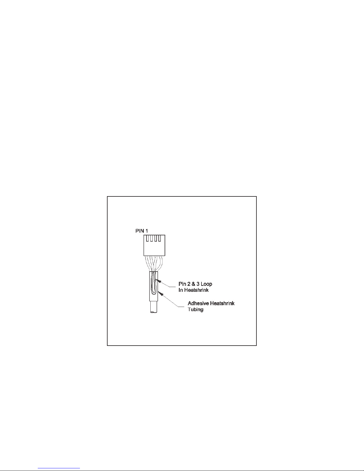
3. Water softener connector details:
A) Terminate end with one Molex white housing.
P/N CLN 09-50-8043 and four Molex pins.
P/N CLN 08-50-0108
B) Water softener Pin 1 = 24.0 VAC
Water softener Pin 2 = Jumper to Pin 3
Water softener Pin 3 = Jumper to Pin 2
Water softener Pin 4 = 24.0 VAC Black
11
Page 3
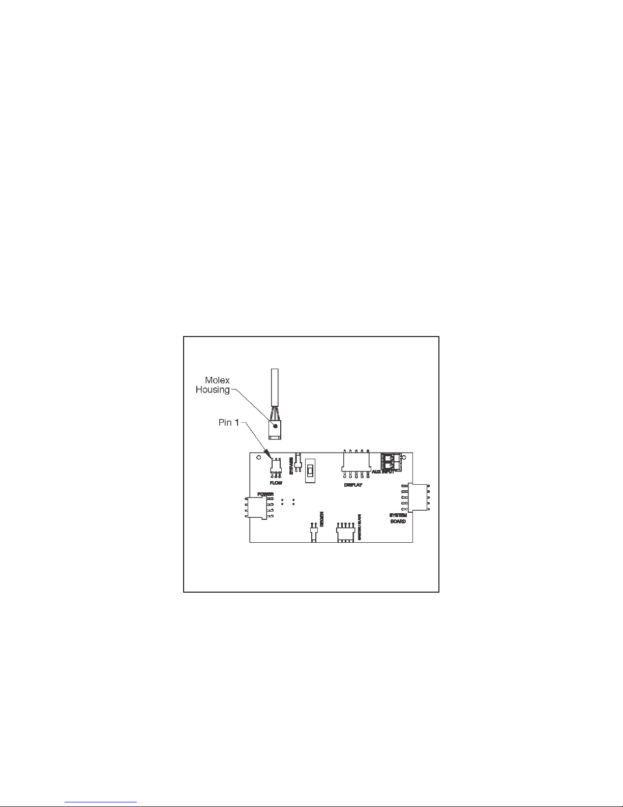
Water Softener Custom Meter Wiring:
1. Water softener terminate end with a Molex series 2695 housing, Pin 22-01-3037 and (3)
Molex series 41572 (or 40445) Pins, Pin 08-65-0805 (or 97-00-44).
2. Water auxiliary meter must be able to operate on 5VDC.
Water softener Pin 1 = + 5VDC
Water softener Pin 2 (centre) = SIGNAL
Water softener Pin 3 = GROUND
3) Water softener acceptable pulse input is .1 - 999 pulse/gallon, or .4 - 519 pulses/litre.
12
Page 4
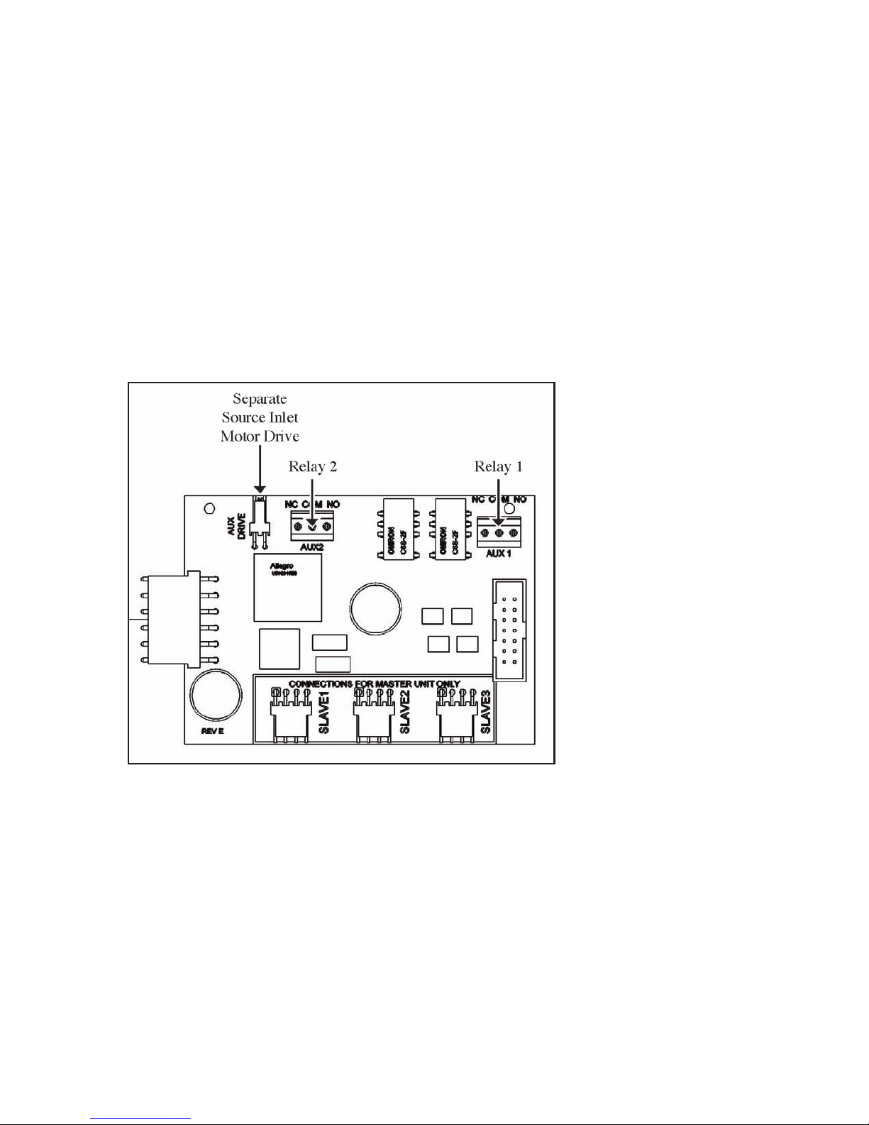
Water Softener Optional System Board:
Water softener system board required for relay output and separate source inlet.
1) Water softener relay outlets 1 and 2 are normally open SPST dry contacts.
2) Water softener maximum power through water softener relays to be
a) 1A, 30VDC
b) 1A, 30VAC
3) Water softener separate souce inlet dreives require connection to a P/N 3063 or P/N 3063
BSPT motorized alternating valve (MAV)
13
Page 5
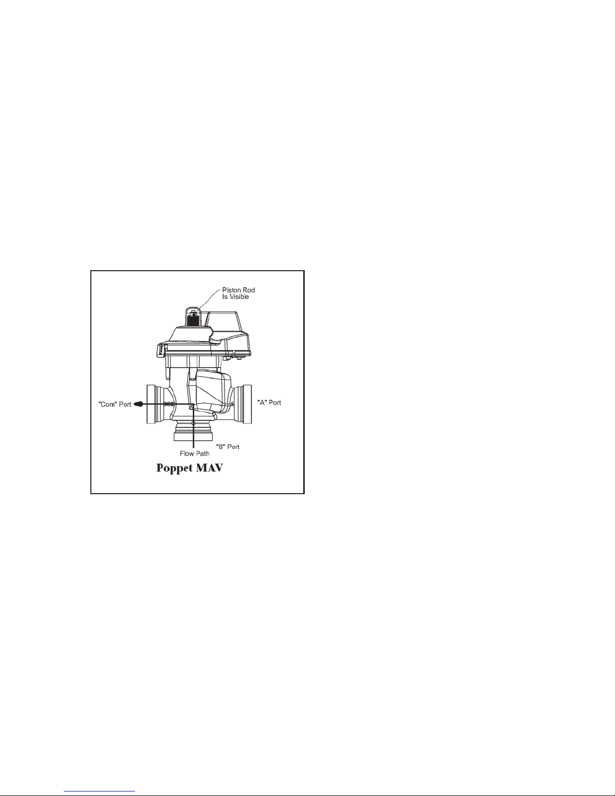
Water Softener Motorized Drive Operation:
Viewing the water softener piston rod through the clear water softener clear dome is
a visual indicator of the water softener drives current position. On the water softener
motorized bypass drive, viewing the rod indicates that the water softener is in service.
Viewing the water softener rod as shown on the water softener MAV indicates that the
water softener common port is currently connected to the water softener “B” port. If
the water softener rod is not visible the water softener is offline in the case of a bypass,
or connected to the water softener “A” port of a MAV. This water softener drive logic is
reversible to meet specific plumbing applications by reversing the polarity of the water
softener drive motor wiring harness as shown below.
14
Page 6
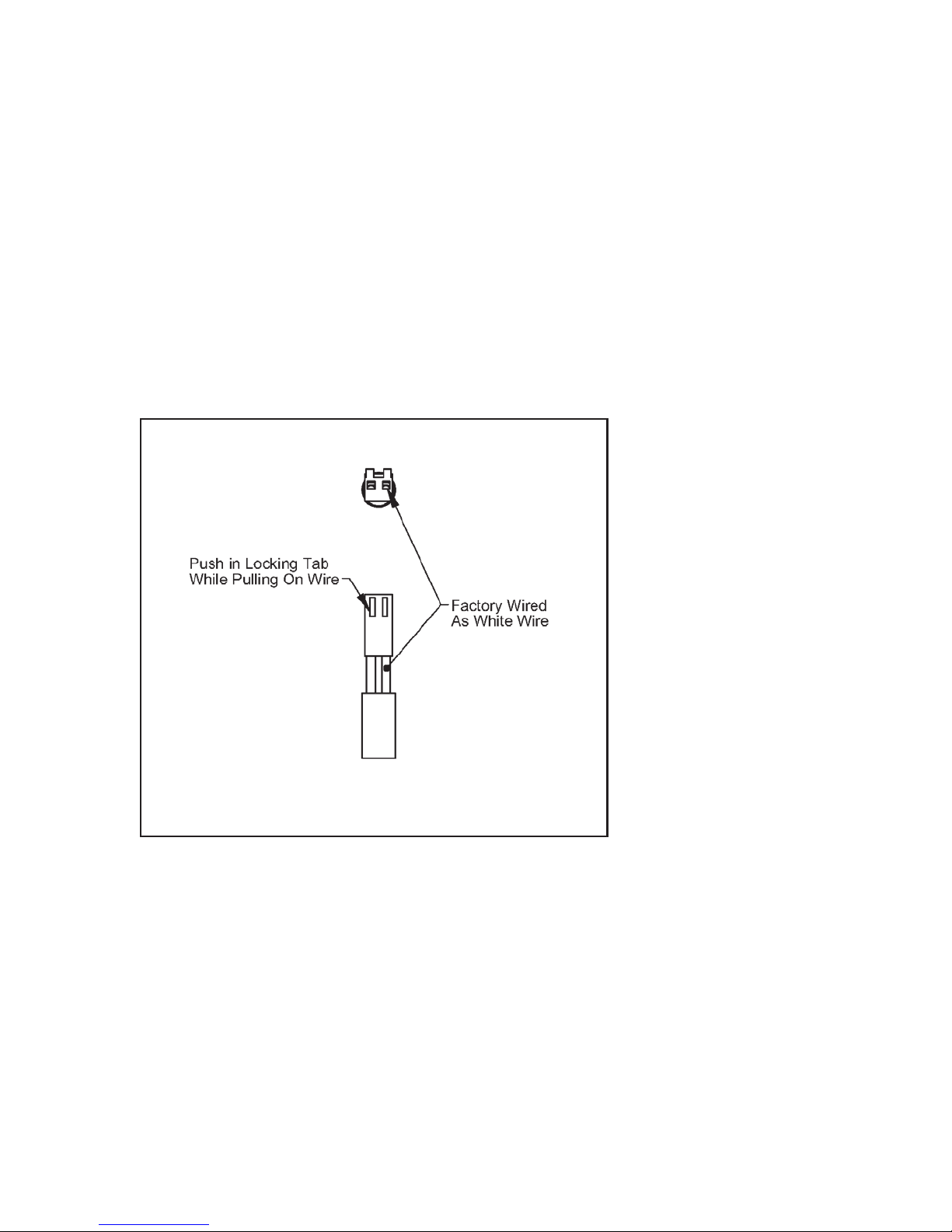
Water Softener Reversing Motorized Drive Direction:
Water softener motorized bypass and water softener MAV drives are factory wired with the
white wire on the right when viewing the water softener wiring harness as shown, reversing
the water softener wires reverses the logic of the drive. The water softener wires can be
removed from the housing by holding down the water softener locking tab in the small
window while applying light pressure to the wire, being careful not to disengage the wire
from its crimped on connector. The water softener wires can then be reinserted, being sure
the water softener locking tab re-engages in the window.
15
Page 7
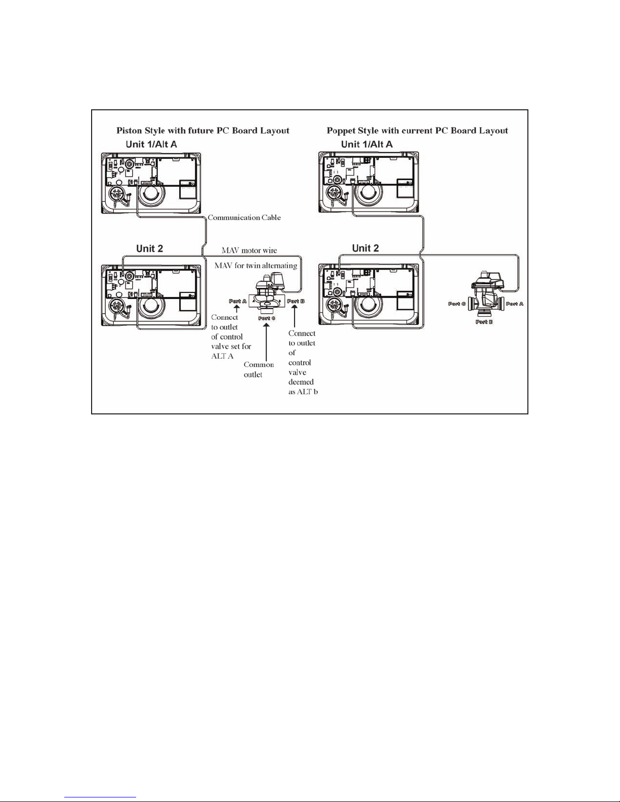
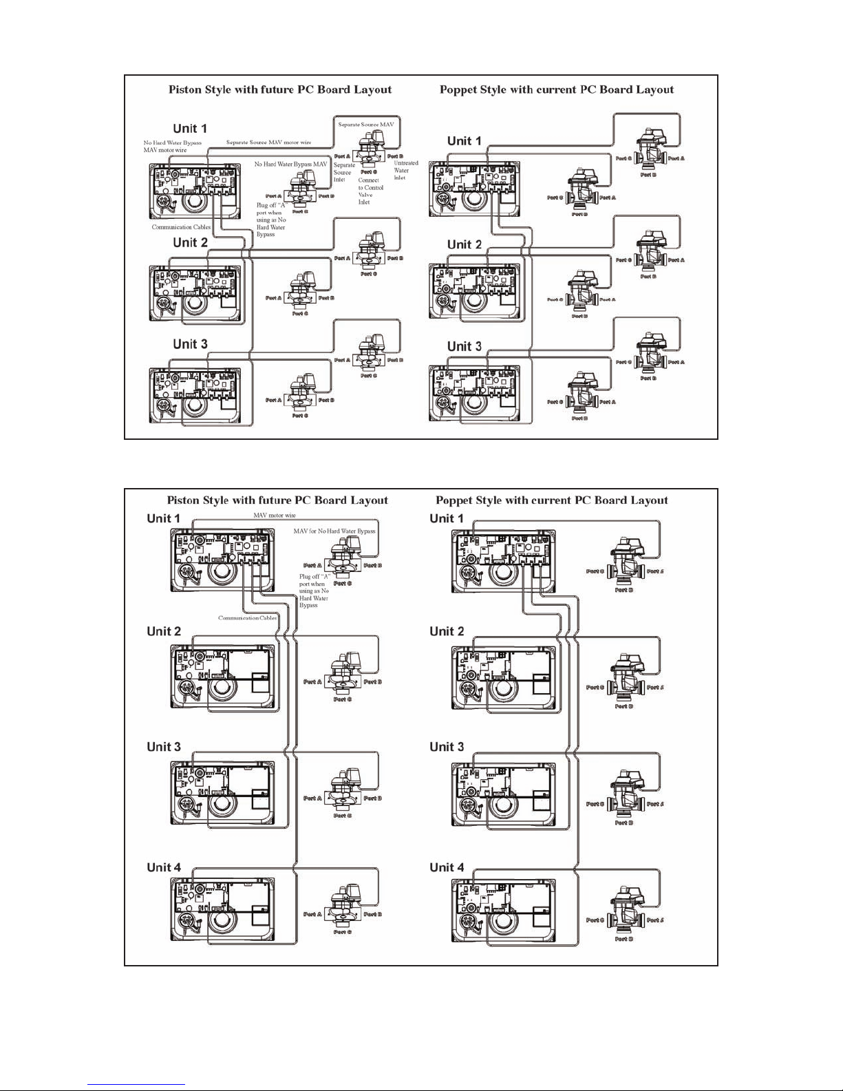
Water Softener Wiring Diagram Examples
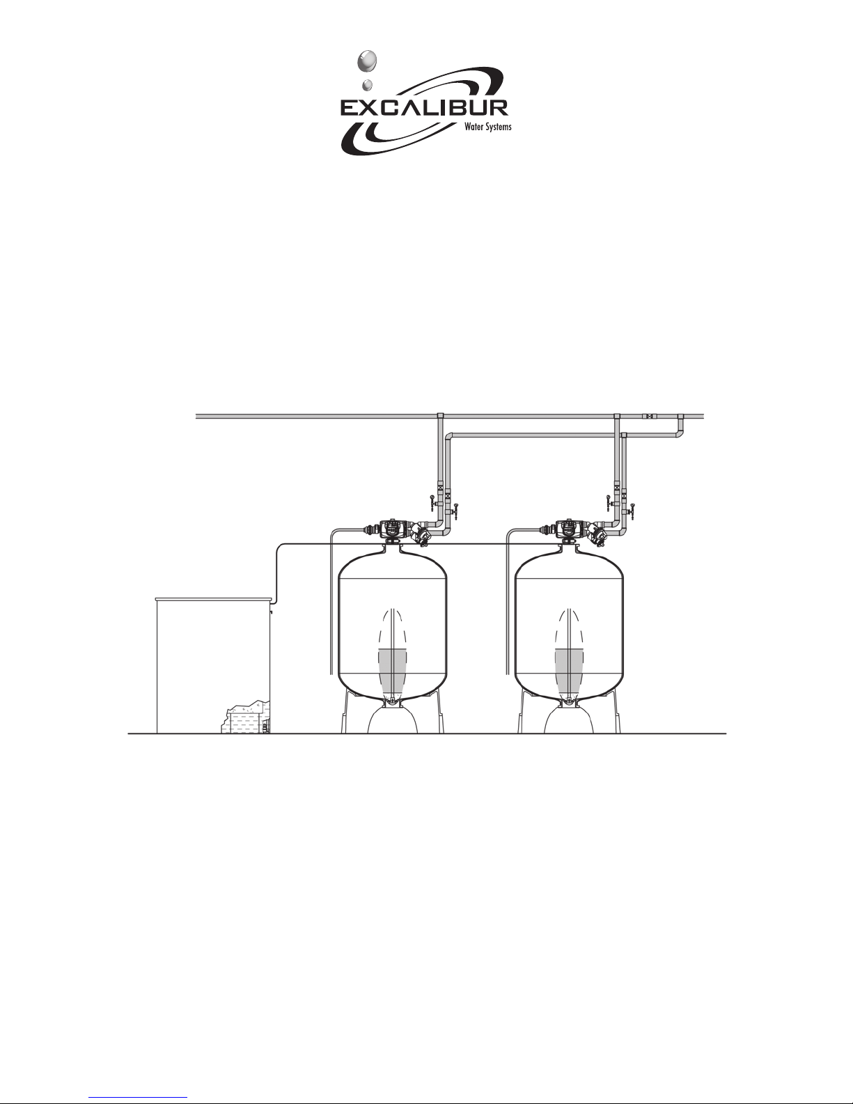
2 Water Softener System:
Water softener dual system with optional system optional system board for water softener
relays outputs and separate source inlet.
16
Page 8
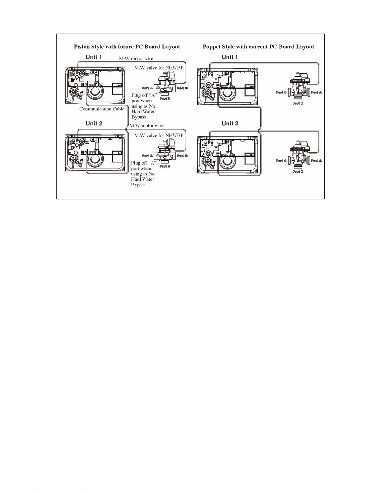
Water softener 3 and 4 unit systems with no optional system boards (4 water softener
shown)
17
Page 9
18
Page 10
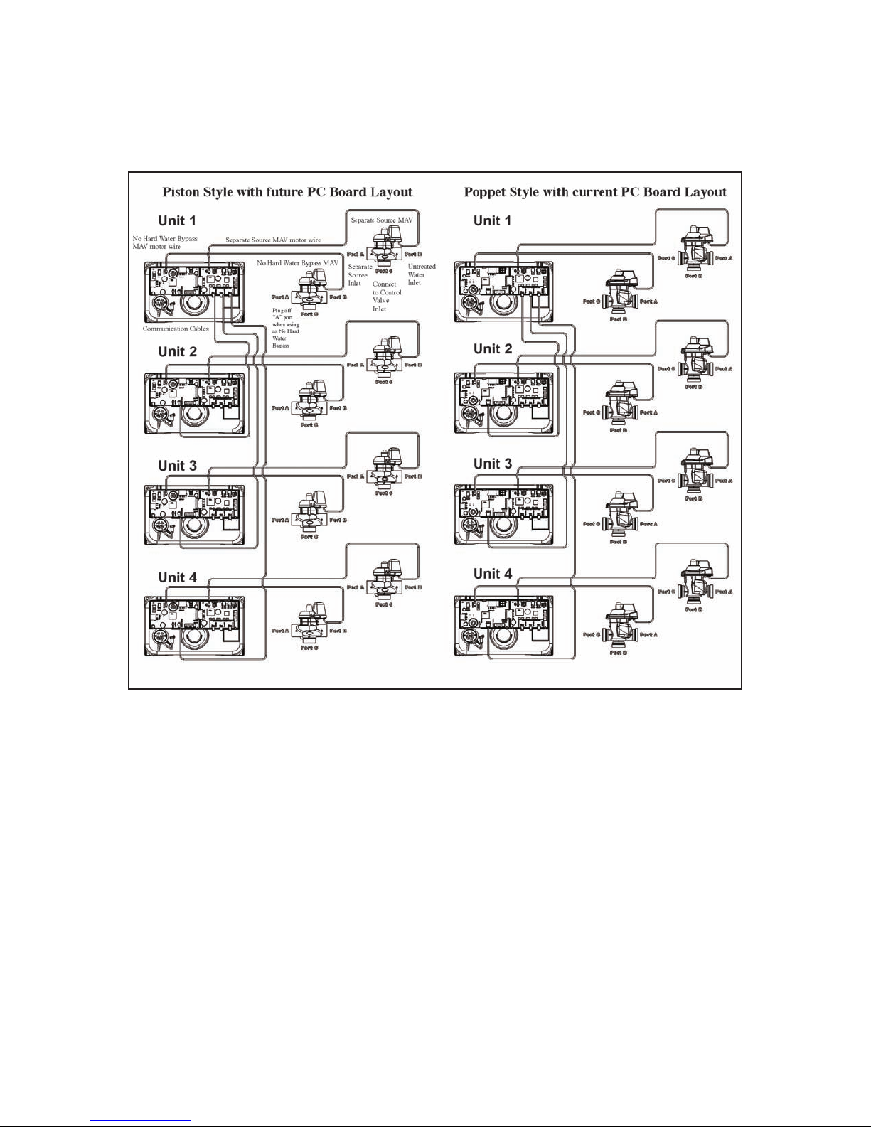
Water softener 3 and 4 unit systems with optional systems boards for water softener relay
outputs and separate inlet (4 water softeners shown)
19
Page 11

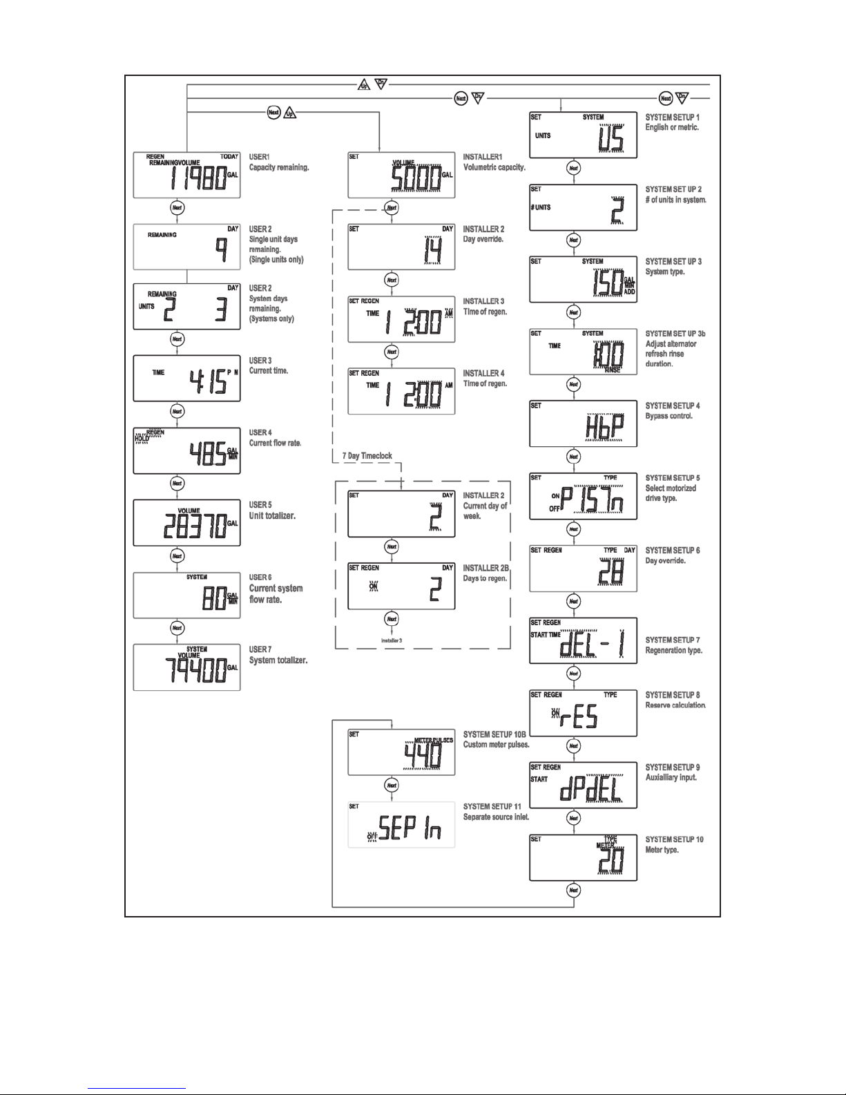
Water Softener Programming Screen Quick Reference:
1. Water softener individual screen descriptions are detailed on the following pages.
2. Some water softener screens have been omitted for clarity.
110
Page 12
111
Page 13

112
Page 14

Water Softener Setting Time of Day:
Water softener set time accessed by pressing
set lock while in the water softener user
screen. Use the up and down water softener
arrows to scroll hours. This water softener
AM/PM alternates at midnight.
Water softener count error and the water
softener number will flash when it is not
detected. Pressing any button will return the
user to the water softener set up screen to
correct the valve.
Water softener error screen:
Water softener error and the code alternate.
The water softener returns and flashes it’s 3
LED’s. The water softener continues to try and
function, but must be reset to correct the
water softener error screen.
113
Page 15

Water Softener Typical User Screens:
Water softener regen today wil display
when a regeneration is scheduled or
flash for a manually set regeneration.
Water softener capacity remaining can be adjusted in 10 gallon increments by holding the
water softener down arrow for > 3 seconds.
Water softener user 1 displays capacity
remaining. Does not display if volumetric
capacity is set to OFF.
Water softener displays days remaining does
not display if days override is set to OFF.
The water softener days remaining can be
decremented one day at a time by holding
the water softener down arrow > 3 seconds.
Water softener hold or start
regen will flash in all user
screens while the water
softener auxiliary input is
activated
Water softener displays time of day.
Water softener displays the
current flow rate.
114
Page 16

Water Softener Typical User Screens Continued:
Water softener displays total water softener
volume since install/reset individually
re-settable using history reset sequence.
Water softener displays the water softeners
current system flow rate. The water softener
does not display on single tank water
softeners.
Water softener total system volume since
install/reset individually re-settable using
history reset sequence. The water softener
does not display on single tank water
softener.
115
Page 17

Water Softener System Set Up Screens:
Water softener accessed by pressing next and down simultaneously for > 3 seconds.
Water softener select country US or SI. This
sets the water softener use of 12 or 24 hour
clock and the water softener display of
gallons or litres.
Select the water softener total number of
water softener tanks from 1 - 4, in a water
softener system. This water softener screen
will only allow 1 or 2 if a water softener
system board is not installed.
Select water softener flow rate and water
softener add point.
1. If water softener is set to “0”, all the
water softeners are online, unless one is
regenerating.
2. If the water softener is greater than 0, the
water softener acts as an alternator water
softener, keeping one water softener offline
at all times. The water softener screen will
not display if set to one water softener.
116
Page 18

Single water softeners have a selection of
hard water bypass, no hard water bypass
or water softener relay operation. When
the water softeners start to regenerate, the
water softener hard water bypass will allow
hard water bypass, no hard water bypass or
water softener relay and two water softeners
alternators have an additional selection of
ALT-A setting the water softener no hard
water bypass requires a motor driven water
softener bypass. The water softener ALT-A
requires a motor driven alternator valve on
the controlling water softener and relay relies
on external valving for no hard water bypass
control.
The water softener select day control type,
time clock 1-28 days, time clock 7 day, or OFF.
When the water softener volumetric capacity
is set, volume regeneration can be combined
with time clock control. OFF will not be an
option if volumetric capacity is off.
117
Page 19

Water Softener Installer Setup Service Returns to Normal Operation
After 5 Minutes:
The water softener is accessed by pressing the water softener next and down
simultaneously for > 3 seconds.
Installer 1:
Set water softener volumetric
capacity or OFF. OFF will not be
an option if the water softener
day control is set to OFF. x 1000
water softener illuminates at
10,000 gallons.
Set water softener current day
and regen days when the water
softener is set as a 7 day time
clock or hybrid in system setup 1.
Installer 2:
Set water softener day override 1-28 days
between regenerations, or if the water
softener is set to 7 day time clock, see 7 day
water setup below. OFF will display if selected
in water softener day control screen installer 3.
Select water softener time of regen. Use water
softener up and down arrows to scroll hours
AM/PM water softener alternates at midnight
“ONO” will be displayed on water softener
with no time dependent regen control.
118
Page 20

Installer 4:
Select water softener time of regen. Use
water softener up and down arrows to scroll
minutes.
Installer 5:
Select water softener time
of 2nd water softener regen
(if configured as a multiple
regenerating water softener).
Installer 2:
Water softener 7 day time clock option to set
water softener current day of the week.
1 - Sunday
2 - Monday
3 - Tuesday
4 - Wednesday
5 - Thursday
6 - Friday|
7 - Saturday
Installer 2B:
Water softener scroll through days 1 - 7 using
the water softener up and down arrows.
Pressing the water softener set clock will
toggle the water softener regen ON or OFF
for that day (ie; regen is on Monday)
Installer 2C:
(ie; no water softener regeneration on
Saturdays)
119
Page 21

Water Softener Setup Screens Continued:
System Setup 6:
Select water softener regeneration type
Water softener delayed (DEL-1)
Water softener delayed (DEL-2)
Water softener delayed (DEL-3)
Water softener delayed (DEL-4)
ONO
Water softener delayed with multiple
regenerations allowed per day would be used
either to reduce the water softener reverse
volume, or to accommodate a small water
softener system relative to the treatment
demand.
System Setup 7:
Select water softener reserve calculation ON
or OFF. OFF will schedule a regen when the
water softener volumetric capacity reaches 0.
This water softener screen will not display for
“ONO”
Water softener delayed with multiple
regenerations allowed per day would be used
either to reduce the water softener reverse
volume, or to accommodate a small water
softener system relative to the treatment
demand.
System Setup 8:
Set water softener auxiliary initiated regen.
Start water softener time regen. Regeneration
will start immediately after 2 cumulative
minutes of switch closure. Start water softener
regen: Regeneration will start immediately
upon switch closure. Start water softener
regen del: regeneration will start at the water
softener delayed time upon closure.
Hold water softener regen:
Regeneration will not be allowed as long as
there is switch closure.
120
Page 22

System Setup 9:
Select water softener meter type or pulses.
Water softener 2.0 meter (type)
Water softener 1.5 meter (type)
Water softener system pulses.
System Setup 9B:
Select water softener meter type pulses.
Water softener screen does not show if
pulses or water softener system pulses is
not selected in the previous water softener
screen.
System Setup 10:
Water softener separate source inlet. This
water softener screen will not display if a
water softener system board is not installed.
121
Page 23

Water Softener Time Screens Water Softener Returns to Normal
Operation After 5 Minutes:
Water softener is accessed by pressing the water softener next and down simultaneously for
> 3 seconds, then by pressing next and down simultaneously again for > 3 seconds.
Timer 1 - A:
Select water softener time of cycle 1.
The water softener press next and down reset
from this screen unlocks the setup screens.
Timer 1 - B:
Select water softener time of cycle 2. “1” is
displayed if the water softener is set for more
than one sequence.
The following water softener screens only
show if the water softener is programmed for
multiple water softener regenerations in the
cycle setup 2 screen.
Timer 1 - A2
Water softener select time of alternate regen
cycle 1
122
Page 24

Timer 1 - B2
Select water softener timer of alternate regen
cycle 2.
123
Page 25

Water Softener Timer Screens Continued:
Timer 2:
Set water softener output 1, these water softener
settings will only be allowed with water softener
system board installed.
Time: Water softener relay is turned on after the water
softener specified time from the start of the water
softener regeneration and is left on for a specified
time.
Cycle: Water softener relay is turned on after the water
softener starts on a specified cycle and is left on for a
specified time.
Volume: The water softener relay is turned on, during
the water softener service flow only. Every specified
number of water softener volume units and is left on
for a specified time.
Volume and Regeneration: The water softener relay is
turned on every specified number of water softener
units and is left on for a specified time.
STBY: The water softener relay would be used to
control external valving, closing for water softener
regeneration, and is left on for a specified time.
REGEN: The water softener relay closes when the water
softener is in regeneration.
ERR: The water softener relay closes when the water
softner is in any error mode.
124
Page 26

Water Softener Timer Screens Continued:
Timer 3:
Set water softener output 2, these water softener
settings will only be allowed with water softener
system board installed.
Time: The water softener relay is turned on after the
water softener starts on a specified time from the
start of water softener regeneration and is left on for a
specified time.
Cycle: The water softener relay is turned on after the
start of a specified water softener cycle and is left on
for a specified time.
Volume: The water softener relay is turned on, during
the water softener service flow only. Every specified
number of water softener volume units and is left on
for a specified time.
Volume and Regeneration: The water softener relay is
turned on every specified number of water softener
volume units and is left on for a specified time.
STBY: The water softener relay would be used to
control external valving, closing for water softener
regeneration or when the water softener would be
offline in systen operation.
REGEN: The water softener relay closes when the water
softener is in regeneration.
ERR: The water softener relay closes when the water
softner is in any error mode.
125
Page 27

Water Softener Timer Screens Continued:
Timer 4:
Select water softener output 1. On water softener
trigger set point per water softener previously selected.
This water softener screen will not display if the water
softener does not have a water softener system board,
or if the water softener STBY was selected as the
trigger.
Time: The water softener time after the start of water
softener regen before switch is closed.
Cycle: Select a water softener cycle which will close
water softener output 1.
Volume: The water softener volume of water interval
during service between water softener switch closures.
The water softener timer 4 and 6 screens will not
display if the water softener display if STBY, REGEN, or
ERR are selected in water softener timer 2 and 3.
Timer 5:
Select water softener output 1 on duration before
turning off. This water softener screen will not display
if the water softener does not have a water softener
system board.
126
Page 28

Water Softener Timer Screens Continued:
Timer 6:
Select water softener output 2, on water softener
trigger set point, per water softener previously
selected. This water softener screen will not display
if the water softener does not have a water softener
system board, or if STBY was selected as the water
softener trigger.
Time: The water softener time after the start of water
softener regen before the water softener switch is
closed.
Cycle: Select a water softener cycle which will close the
water softener output 2.
Volume: The water softener volume of water interval
during service between water softener switch closures.
127
Page 29

Water Softener Timer Screens Continued:
Timer 7:
Select water softener output 2 on duration before
turning off. This water softener screen will not display
if the water softener does not have a water softener
system board.
128
Page 30

Water Softener Cycle Setup Screens:
Water softener returns to normal operation after 5 minutes.
Water softener is accessed by pressing water softener next and down buttons
simultaneously for > 3 seconds, then by pressing water softener next and down buttons
simultaneously again for > 3 seconds, then by pressing water softener next and down
buttons simultaneously again for > 3 seconds a third time.
Water softener cycle setup 1 - A
Select water softener first cycle.
Water softener cycle
setup 1 - B
Select water softener
second cycle.
Water softener cycle setup 1 - C
After water softener cycles are configured, a water
softener end is added. Water softener (9 cycles
maximum)
129
Page 31

Water Softener Cycle Setup Screens Continued:
Water softener cycle setup 2.
Water softener select regeneration repeats, 1 - 10
or OFF. Water softener repeats regeneration cycle
sequence 1 as selected number of times before water
softener regenerates a single time with sequence 2.
The following watre softener screens only show if
the water softener is programmed for multiiple water
softener regenerations in the previous water softener
screens.
Water softener cycle setup 3 - A
Select water softener first cycle of “alternate” water
softener regeneration sequence.
Water softener cycle setup 3 - B
Select water softener second cycle of alternate water
softener regeneration sequence.
Water softener cycle setup 3 - C
After water softener cycles are configured, a water
softener end is added, water softener (9 cycles
maximum)
130
Page 32

Water Softener Diagnostic Screens:
Return water softener to normal operation after 5 minutes.
Water softener is accessed by pressing water softener next and down buttons
simultaneously for > 3 seconds.
All water softener diagnostic history screens are resettable with the water softener history
reset sequence while in the water softener diagnostics 1 screen. Holding the water softener
set clock and water softener regen buttons for > 3 seconds initiates a totalizer or history reset.
Water softener diagnostics 1
= days since the last water softener regeneration
Water softener reserve valve.
Water softener diagnostics 2
Water softener gallons or litres since the last water
softener regeneration
Water softener diagnostics 3
Water softener reserve history - this water softener
screen onlly appears if valve is set to calculate water
softener reserve in water softener setup 7. Use arrows
to select water softener A day. 0 = today, 1 = yesterday,
6 = 6 days ago (MAX)
Water softener automatically toggles
131
Page 33

Water Softener Diagnostic Screens Continued:
Water softener diagnostics 4
Water softener history of volume used
Use water softener arrows to select A day
0 = today
1 = yesterday
63 = 63 days ago (MAX)
Water softener regen will display if a water softener
regeneration occurs that day.
Water softener gallons used
Water softener automatically toggles
Simultaneously press water
softener up and down buttons
Water softener diagnostics 4 - B
The water softener hourly history
of water softener volume use.
Use the water softner up and
down buttons to select the water
softener hours of the day from
water softener screen 4.
Water softener volume used within the water softener selected hour.
Water softener automatically toggles
132
Page 34

Water Softener Diagnostic Screens Continued:
Water softener diagnostics 5
The water softener maximum flow rate for the last 28 days.
The water softener maximum flow rate of the day.
Water softener automatically toggles
Simultaneously press the water softener up and
down buttons.
Water softener diagnostic 5 - B
The water history of maximum flow rate. Use the water
softener up and down buttons to select the water
softener hours of the day from water softener screen 5.
The water softener maximum flow within the watch softener
selected hour.
Water softener automatically toggles
133
Page 35

Water Softener Diagnostic Screens Continued:
Water softener diagnostics 6
Water softener total volume through
the water softener.
Water softener diagnostics 7
Water softener system totalizer for the last 63 days.
Water softener only displays in a mater system.
Water softener use for that day
Water softener automatically toggles
Simultaneously press water softener up and down.
Water softener diagnostics 7 - B
The water softener hourly system totalizer. Use water
softener up and down buttons to select water softener
hour of day from water softener screen 7
134
Page 36

Water Softener Diagnostic Screens Continued:
Water softener total system flow for the selected hour
Water softener automatically toggles
135
Page 37

Water Softener Valve History:
Water softener returns to normal operation after 5 minutes non resettable
Water softener accessed by pressing water softener up and down buttons simultaneously
for > 3 seconds, then by pressing water softener up and down buttons simultaneously
again for > 3 seconds.
Water softener history 1
Water softener total days since startup. Water softener
time only accumulates while the water softener is
plugged in.
Water softener history 2
Water softener total regenerations since startup.
Water softener history 3
Water softener total volume since startup.
136
Page 38

Water Softener Error Codes:
137
 Loading...