

Excalibur Water Systems S50BF, S40BF, SB27BF, SB64BF, SB34BF Installation And User Manual
...
SIMPLEX VALUE WATER SOFTENER
INSTALLATION AND USER GUIDE

1
SOFTENER INSTALLATION AND USER GUIDE
TABLE OF CONTENTS
1) Installation ............................................................................................................................................ 2
1.1) Pre-installation instructions .......................................................................................................... 2
1.2) General Installation and Service Warnings ................................................................................... 2
1.3) Site Requirements ......................................................................................................................... 2
1.4) Installation Drawing ...................................................................................................................... 3
1.5) System Drawing ............................................................................................................................ 4
1.6) Plumbing Instructions ................................................................................................................... 4
1.7) Brine Line Connection ................................................................................................................... 5
1.8) Overflow Line Connection ............................................................................................................. 5
1.9) Drain Line ...................................................................................................................................... 5
1.10) Bypass Valve .............................................................................................................................. 6
1.11) Start Up Instructions ................................................................................................................. 7
2) Control Valve Programming .................................................................................................................. 8
2.1) Regeneration Screens ................................................................................................................... 8
2.2) Button Operation .......................................................................................................................... 8
2.3) Setting Time of Day ....................................................................................................................... 9
2.4) User Displays ................................................................................................................................. 9
2.5) Installer Display Settings ............................................................................................................. 10
2.6) Softener System Setup ................................................................................................................ 11
3) Model Variable Components and Specifications ................................................................................ 12
3.1) Flow Controls and Injectors ........................................................................................................ 12
3.2) Specifications .............................................................................................................................. 12
4) Control Valve Cycles ............................................................................................................................ 13
5) Components of Control Valve ............................................................................................................. 15
5.1) Front Cover and PC Board ........................................................................................................... 15
5.2) Drive assembly, Piston and Spacer stack .................................................................................... 16
5.3) Injector Assembly ........................................................................................................................ 17
5.4) Brine Tank Line Flow Control ...................................................................................................... 18
5.5) Drain Line Flow Control Assembly .............................................................................................. 19
5.6) Outlet Meter Assembly ............................................................................................................... 20
5.7) Bypass Valve Components .......................................................................................................... 21
5.8) Installation Fitting Assemblies .................................................................................................... 22
6) Brine Tank Assembly ........................................................................................................................... 24
7) Troubleshooting .................................................................................................................................. 25
7.1) Possible Error Codes ................................................................................................................... 25
7.2) Troubleshooting Procedures ....................................................................................................... 26
8) Quick Reference Guide ....................................................................................................................... 29
9) Warranty ............................................................................................................................................. 31
BARRIE ● ONTARIO ● CANADA 705.733.8900 WWW.EXCALIBURWATER.COM

SOFTENER INSTALLATION AND USER GUIDE
1) INSTALLATION
1.1) Pre-installation instructions
The cycle times, sequence of cycles, salt dose refill time and exchange capacity are preset to by
Excalibur. The dealer must guide the installer to change the values according to the hardness, day
override and time of regeneration.
WATER TEST
Hardness gpg
Iron ppm
pH number
Nitrates ppm
Manganese ppm
Sulphur yes/no
Total Dissolved Solids
2
1.2) General Installation and Service Warnings
• The softener is designed so that it can be installed easily with minor plumbing changes on
previous plumbing.
• The piping must be clamped properly and the weight of the plumbing must not be on the
softener.
• Do not use any kind of lubricant including silicone. A silicone based lubricant can be only used on
black O-Rings but not necessary.
• Do not use pipe dope or other sealant on plastic nuts and caps. Teflon tape must be used only on
NPT threads.
• The nuts and caps can be fastened and unfastened by hand or the plastic service wrench. Do not
use pipe wrench to tighten the caps and nuts.
1.3) Site Requirements
• Water Pressure: - 40-110 psi
• Water Temperature: - 40-110°F (4.4-43°C)
• Electrical- 115/120 V, 60Hz Uninterrupted Outlet
• Current required is 0.5 Amperes with plug-in transformer (dry locations only).
• The tank should be on a firm level surface
BARRIE ● ONTARIO ● CANADA 705.733.8900 WWW.EXCALIBURWATER.COM
SOFTENER INSTALLATION AND USER GUIDE
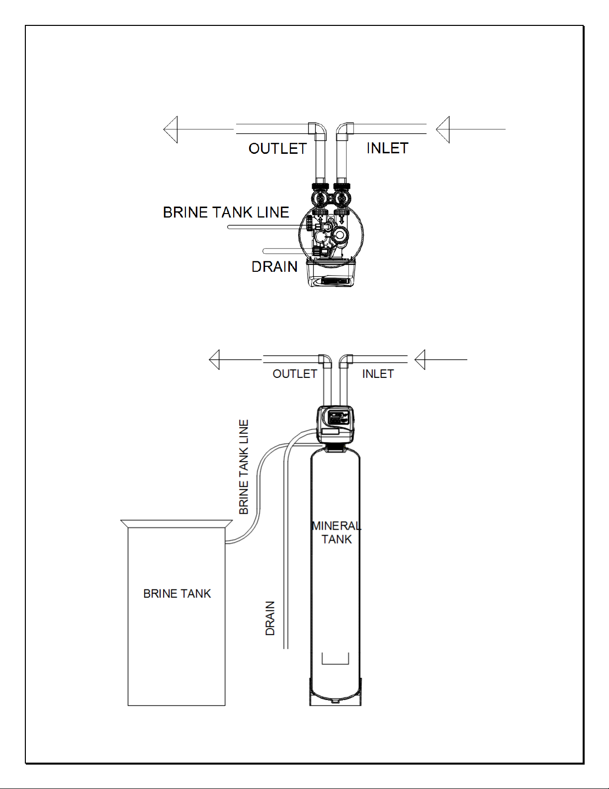
1.4) Installation Drawing
3
BARRIE ● ONTARIO ● CANADA 705.733.8900 WWW.EXCALIBURWATER.COM
SOFTENER INSTALLATION AND USER GUIDE
Water
Pressure
Minimum 10ft
Water
Minimum 10ft
Brine
Brine
Outside
Tap
Outside
Tap
Water
Cold
Cold
Hot
Hot
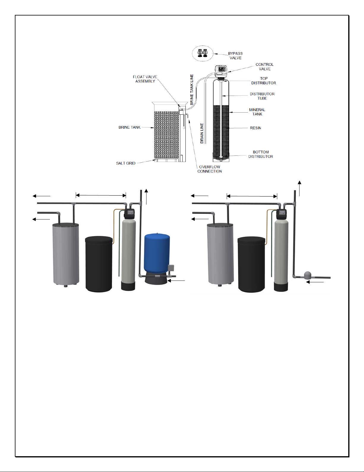
1.5) System Drawing
1.6) Plumbing Instructions
4
heater
Tank
Tank
heater
Tank
Meter
Well Water Installation Municipal Installation
1) The softener must be located at the closest possible location to drain.
2) The water heater’s inlet must be at least 10ft away from softener.
3) The unit including the drain must be located in a room temperature above 33° F.
4) If vacuum occurrence is expected then the vacuum breaker must be installed at the inlet of the
softener.
5) The bypass valve must be installed on the control valve.
6) The outside tap water if possible may be bypassed from the softener.
7) The primer, solder or solder flux must not get on the O-rings while installation.
8) After soldering the lines must be cooled before installing the O-Rings, nuts and caps.
9) If the electrical system is grounded to the plumbing, then a copper strap must be connected
between inlet and outlet as shown in figure above.
10) The plumbing must be done by following the local plumbing codes.
BARRIE ● ONTARIO ● CANADA 705.733.8900 WWW.EXCALIBURWATER.COM

SOFTENER INSTALLATION AND USER GUIDE
Tank Brine Line
Brine Line
Drain Line
1.7) Brine Line Connection
Install 3/8” O.D. Polyethylene tube according to specification sheet from the brine tank to the control
valve.
5
Connection
1.8) Overflow Line Connection
• Only used where brine tank overflow water spillage can damage flooring or structure.
• Brine tank is equipped with safety float valve which prevents the overflow in case if control
valve fails to control the refill cycle.
• In case if safety float also fails to stop refill then only the water will come through overflow line
connection.
1.9) Drain Line
• The ½” tubing must be used for drain line.
• Leave minimum of 6” gap between flow control fitting and solder joints. The gap less than this
can damage the flow control.
• If the drain line is elevated and then emptied into the drain below the level the of control valve
then 7” loop should make at the end of drain line.
• The air gap between the drain and the end of the drain line must be twice the diameter of the
tube.
• The drain line must be clamped or strap tied at the end to secure in position.
BARRIE ● ONTARIO ● CANADA 705.733.8900 WWW.EXCALIBURWATER.COM
SOFTENER INSTALLATION AND USER GUIDE
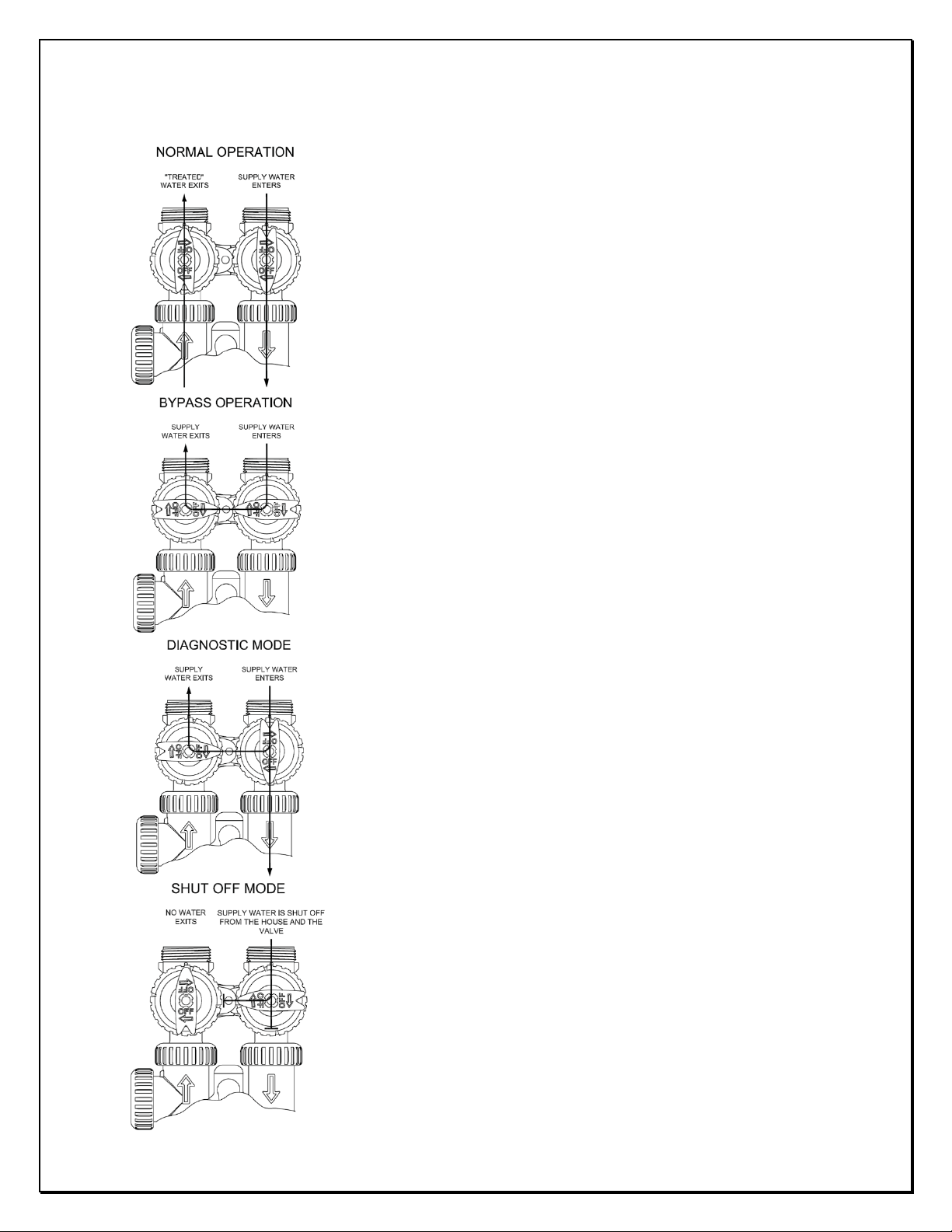
NORMAL OPERATION
BYPASS OPERATION
DIAGNOSTIC MODE
SHUT OFF MODE
1.10) Bypass Valve
6
The inlet and outlet handles of bypass valve should be pointing the
direction of flow indicated by the engraved arrows on the control valve.
Water flows through the control valve in normal operation as a water
softener.
The inlet and outlet handles point to the center of the bypass valve.
The system is isolated from the water pressure in the plumbing
system. Untreated water is supplied to the house in this position.
The inlet handle points in the direction of flow and the outlet
handle points to the center of bypass valve, system water pressure
is allowed to the control valve and the plumbing system while not
allowing water to exit from the control valve to the plumbing.
Untreated water is supplied to the house in this position.
The inlet handle points to the center of the bypass valve and the
outlet handle points in the direction of flow, the water is shut off
to the plumbing system. If water is available on the outlet side of
the Softener, it is an indication of water bypass around the
system.
BARRIE ● ONTARIO ● CANADA 705.733.8900 WWW.EXCALIBURWATER.COM

SOFTENER INSTALLATION AND USER GUIDE
1.11) Start Up Instructions
• Keep the bypass valve in bypass operation by moving both handles pointing towards the center
of bypass valve. Now the untreated water is being supplied to house. Open the faucet
downstream of the softener until water comes clear out of it. The initial water can be dirty
because of installation debris. Now inspect the leaks in plumbing.
• Manually add approximate 6 inches of water to brine tank so that level reaches air check valve.
• Press and hold the “REGEN” button down for 5 seconds to start manual regeneration. The drive
motor will start to reach backwash cycle and countdown time begins. Turn the inlet bypass valve
handle halfway into the direction of diagnose operation. Once the steady water flows out of
drain then fully turn both handles of bypass valve into the direction of service operation.
7
Caution: - If water flow is too rapidly, there will be a loss of resin to drain.
• When the water become clear in drain line then press the regen button to advance the
regeneration to brine cycle. Lift off the brine tank lid to check if water is being drawn from brine
tank and shut off the faucet after confirming the brine draw flow.
• Press REGEN button to advance the regeneration to 2
nd
backwash cycle. Wait until the
countdown time starts.
• Press REGEN button again to advance the regeneration to rinse cycle with water coming through
the drain. Allow this process for the full amount of time during this cycle.
• The control valve will automatically advance the regeneration to the fill cycle. Allow to fill for the
full amount of time in this cycle. Once finished the control valve will automatically come to the
service position with the time of day being displayed.
• Add the salt to Brine Tank.
BARRIE ● ONTARIO ● CANADA 705.733.8900 WWW.EXCALIBURWATER.COM
SOFTENER INSTALLATION AND USER GUIDE
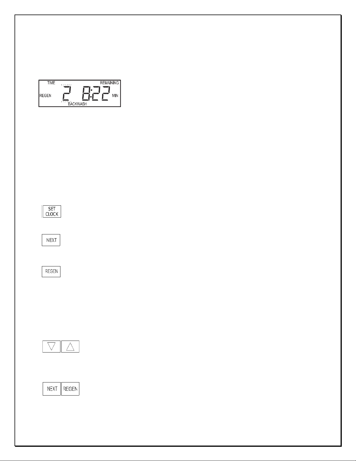
Regen Screen
Scrolls to the next display.
• Pressing once and releasing will schedule a regeneration at the preset delayed regeneration time.
Change Variable being displayed.
Holding for 3 seconds initiates a control reset. The software version is displayed and the
piston returns to the home/service position, resynchronizing the valve.
• Sets time of day
Regeneration occurs automatically if volume capacity drops below the reserve capacity
last regeneration.
2) CONTROL VALVE PROGRAMMING
2.1) Regeneration Screens
automatically predicted by Control Valve or the has control valve reached 14 number of days since
2.2) Button Operation
• Displays the time remaining in the current cycle.
• Displays the cycle name and sequence number.
• Pressing REGEN advances to the next cycle.
8
• Save changes and Exit to user display from any programming screen
• Pressing again and releasing will cancel the delayed regeneration.
• Pressing and holding for 3 seconds will initiate an immediate regeneration
• Pressing while in regeneration will advance to the next cycle.
• Pressing in the program levels will go backwards to the previous screen
BARRIE ● ONTARIO ● CANADA 705.733.8900 WWW.EXCALIBURWATER.COM
SOFTENER INSTALLATION AND USER GUIDE
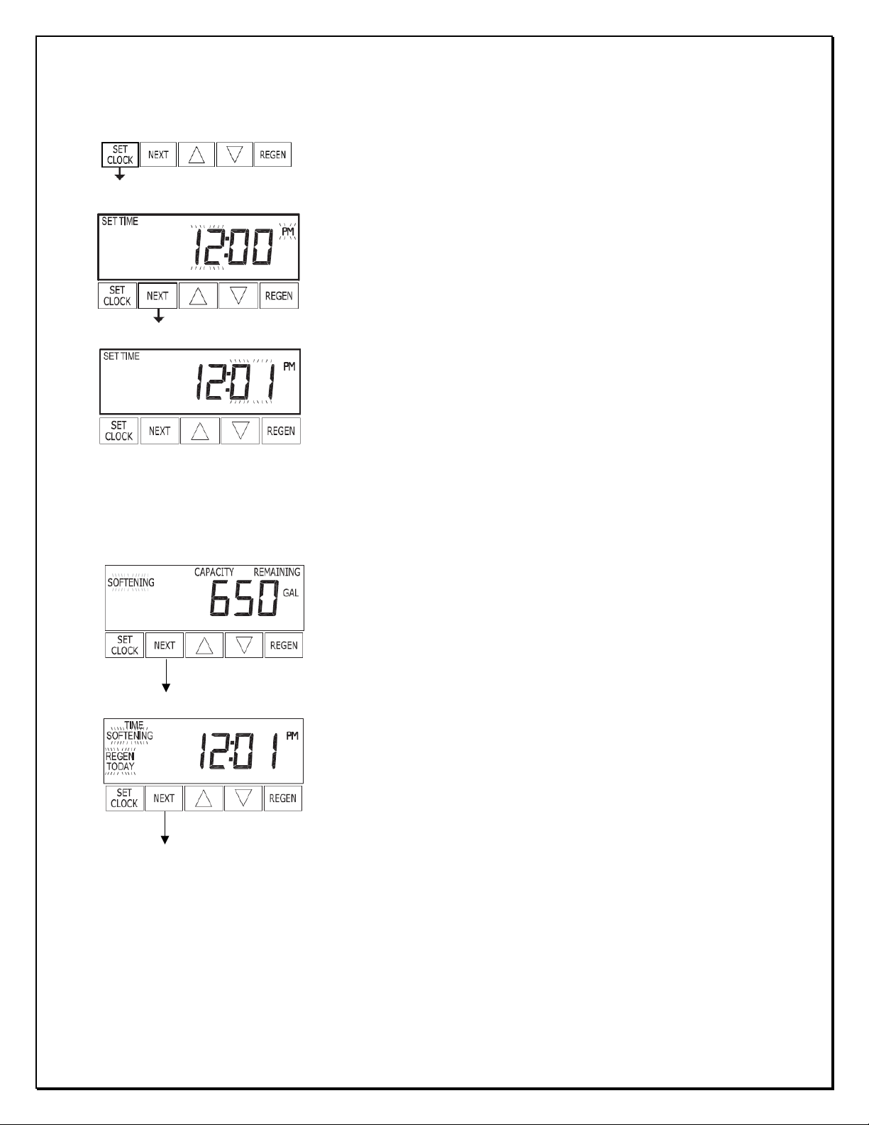
When the system is operating, one of displays given below may be
Push SET CLOCK button.
Return to User Display 1
2.3) Setting Time of Day
When hour flashes press ▲ or ▼ until the correct hour is displayed.
Then press NEXT.
The minutes will flash. Press ▲ or ▼ until the correct minute is
displayed. Press NEXT to return to the User Displays.
Time of day should only need to be set after power outages lasting
more than 8 hours, if the battery has been depleted and a power
outage occurs, or when daylight saving time begins or ends.
9
2.4) User Displays
shown. Pressing NEXT will alternate between the displays shown below.
User 1
This user display shows the volume capacity remaining.
User 2
Displays current time of the day.
− “SOFTENING” displays when the meter is registering the water.
− “REGEN TODAY” displays when the scheduled regeneration is to
occur at a scheduled time of day.
BARRIE ● ONTARIO ● CANADA 705.733.8900 WWW.EXCALIBURWATER.COM

SOFTENER INSTALLATION AND USER GUIDE
Step 1I - To enter Installer Display press NEXT and ▲ simultaneously
EXIT INSTALLER DISPLAY SETTINGS
2.5) Installer Display Settings
10
for about 5 seconds and release.
Step 2I – Hardness: Set the amount (gpg) of hardness using ▲ or ▼.
Press NEXT to go to step 3I. Press REGEN to exit Installer Display
Settings.
Step 3I – Day Override: Set “14” the maximum number of days
between regenerations.
Press NEXT to go to step 4I. Press REGEN to return to previous step.
Step 4I – Next scheduled regeneration time (hour): Set the hour of
day for regeneration using ▲ or ▼. (Usually 2:00AM or when the
predictable flow is minimum)
Press NEXT to go to step 5I. Press REGEN to return to previous step.
Step 5I – Next scheduled regeneration time (minutes): Set the
minutes of day for regeneration using ▲ or ▼.
Press NEXT to exit Installer Display Settings. Press REGEN to return
to previous step.
BARRIE ● ONTARIO ● CANADA 705.733.8900 WWW.EXCALIBURWATER.COM

SOFTENER INSTALLATION AND USER GUIDE
Step 1S - Press NEXT and ▼ simultaneously for 5 seconds and
2.6) Softener System Setup
11
release.
Step 2S – Choose SOFTENING using ▲ or ▼. Press NEXT to go to
Step 3S. Press REGEN to exit OEM Softener System Setup.
Step 3S – Enter the softening grains capacity given in specification
sheet according to the salt usage.
Step 4S – Enter the pounds of salt usage per regeneration. Press
NEXT to proceed to Step 5S or Press REGEN to return to previous
step.
Step 5S – Select “NORMAL” backwash length. Press NEXT to proceed
to Step 6S.
Step 6S – Set “AUTO” for estimating reserve volume capacity and
total volume capacity automatically.
Step 7S – Set “PoST” Refill location using ▲ or ▼ to refill the brine
tank immediately after the final rinse.
Press NEXT to go to Step 8S. Press REGEN to return to previous step.
BARRIE ● ONTARIO ● CANADA 705.733.8900 WWW.EXCALIBURWATER.COM

SOFTENER INSTALLATION AND USER GUIDE
Model
Number
Mineral Tank
Brine Tank
Injector
Drain Flow Control
Dia X Height (Inch)
(Inch)
Color
Order #
Flow GPM
Order #
EWS S25BF
8x44
Violet
CLK V30101C
1.7
CLK V3162017
EWS S30BF
9x48
Red
CLK V30101D
2.2
CLK V3162022
EWS S40BF
10x54
White
CLK V30101E
2.7
CLK V3162027
EWS S50BF
10x54
White
CLK V30101E
2.7
CLK V3162027
EWS S60BF
12x52
18x33 (Dia x Height)
Blue
CLK V30101F
3.2
CLK V3162032
Dia X
Height
EWS S25BF
8X44
0.83
17,000
5
22,000
8.5
25,000
13
4.2
6.6
70
EWS S30BF
9X48
1.00
20,000
6
27,000
10
30,000
15
5.0
8.0
84
EWS S40BF
10X54
1.33
27,000
8
36,000
13
40,000
20
6.7
10.7
106
EWS S50BF
10X54
1.67
33,000
10
45,000
17
50,000
25
8.4
13.4
124
EWS S60BF
12X52
2.00
40,000
12
54,000
20
60,000
30
10.0
16.0
171
Step 8S – Select “dn” for downflow brine cycle using ▲ or ▼. Press
EXIT SOFTENER SYSTEM SETUP
12
NEXT to go to Step 9S. Press REGEN to return to previous step.
Step 9S – Set “NORMAL” for the regeneration time. Press NEXT to
exit Softener System Setup or Press REGEN to return to previous
step.
3) MODEL VARIABLE COMPONENTS AND SPECIFICATIONS
3.1) Flow Controls and Injectors
14x14x34 (Length x
Width x Height)
3.2) Specifications
Mineral
Model
Number
* Excalibur Softeners are factory programmed to 10lbs/ft
Tank
Resin
Quantity
ft3 6 lbs Salt/ft3 10 lbs Salt/ft3 15 lbs Salt/ft3 Continuous Peak LBS
Grains Capacity
Lbs Salt Setting Flow (GPM)
3
default settings
Shipping
Weight
BARRIE ● ONTARIO ● CANADA 705.733.8900 WWW.EXCALIBURWATER.COM

SOFTENER INSTALLATION AND USER GUIDE
In Service Cycle water flows through the upper basket
In Backwash Cycle water flows in upflow direction, the
Note: - Backwash, Brine and Rinse cycles bypass the
4) CONTROL VALVE CYCLES
13
and flows down to the bottom distributor. In this
operation hardness of water is removed by resin.
water enters the tank from bottom distributor and
collected by upper basket. This operation lifts the bed
and wash the resin. The water goes out through the
drain line.
supply water to the demand.
BARRIE ● ONTARIO ● CANADA 705.733.8900 WWW.EXCALIBURWATER.COM

SOFTENER INSTALLATION AND USER GUIDE
In Brine Cycle water flows in downflow direction
In Rinse Cycle water flows rapidly in downflow
Fill Cycle (Not Shown): - The water flow same as
14
which siphon the brine solution from brine tank and
slow rinse water goes to the drain.
direction through the resin to the drain. This cycle
washes the excess sodium from the resin particles.
Service operation but water also flows to the brine
tank for refilling.
BARRIE ● ONTARIO ● CANADA 705.733.8900 WWW.EXCALIBURWATER.COM

SOFTENER INSTALLATION AND USER GUIDE
Drawing No.
Order No.
Description
Quantity
1
CLK V317501
WS1 Front Cover ASY
1
2
CLK V310701
WS1 Motor
1 3 CLK V310601
WS1 Drive Bracket & Spring Clip
1
4
CLK V310810BOARD
WS1 PCB XMEGA REPL
1
5
CLK V3110
WS1 Drive Reducing Gear 12x36
3
6
CLK V3109
WS1 Drive Gear Cover
1
CLK V3186
WS1 AC ADAPTER 120V-12V
CLK V3186EU
WS1 AC ADAPTER 220-240V-12V
CLK V3186UK
WS1 AC ADAPTER 220-240V-12V
CLK V318601
WS1 AC ADAPTER CORD ONLY
AC Adapter
U.S.
Supply Voltage
120 V AC
Supply
60 Hz
Output Voltage
12 V AC
Output Current
500 mA
Battery
Battery Fully
Replacement
5) COMPONENTS OF CONTROL VALVE
5.1) Front Cover and PC Board
15
Not Shown
Seated
Orientation
1
battery type 2032
BARRIE ● ONTARIO ● CANADA 705.733.8900 WWW.EXCALIBURWATER.COM

SOFTENER INSTALLATION AND USER GUIDE
Drawing No.
Order No.
Description
Quantity
1
CLK V3005
WS1 Spacer Stack Assembly
1
2
CLK V3004
Drive Cap ASY
1 3 CLK V3178
WS1 Drive Back Plate
1 4 CLK V3011
WS1 Piston Downflow ASY
1
5
CLK V3174
WS1 Regenerant Piston
1
6
CLK V3135
O-ring 228
1
7
CLK V3180
O-ring 337
1
8
CLK V3105
O-ring 215 (Distributor Tube)
1
Not Shown
CLK V3001
WS1 Body ASY Downflow
1
5.2) Drive assembly, Piston and Spacer stack
16
BARRIE ● ONTARIO ● CANADA 705.733.8900 WWW.EXCALIBURWATER.COM

SOFTENER INSTALLATION AND USER GUIDE
Drawing No.
Order No.
Description
Quantity
1
CLK V3176
INJECTOR CAP
1
2
CLK V3152
O-RING 135
1
3
CLK V317701
INJECTOR SCREEN CAGE
1
4
CLK V30101Z
WS1 INJECTOR ASY Z PLUG
1
CLK V30101C
WS1 INJECTOR ASY C VIOLET
For 8” Tank
CLK V30101D
WS1 INJECTOR ASY D RED
For 9” Tank
CLK V30101E
WS1 INJECTOR ASY E WHITE
For 10” Tank
CLK V30101F
WS1 INJECTOR ASY F BLUE
For 12” Tank
Not Shown*
CLK V3170
O-RING 011
1
Not Shown*
CLK V3171
O-RING 013
1
5.3) Injector Assembly
17
5
* The injector plug and the injector each contain 011 (lower) and 013 (upper) O-ring.
1
BARRIE ● ONTARIO ● CANADA 705.733.8900 WWW.EXCALIBURWATER.COM

SOFTENER INSTALLATION AND USER GUIDE
Drawing No.
Order No. Description
Quantity 1
CLK V414401
Elbow 3/8 Liquifit Asy w/RFC
1
2
CLK H4615
Elbow Locking Clip
1
3
CLK H4628
Elbow 3/8” Liquifit
1 4 CLK V3163
0-ring 019
1
5
CLK V316501
WS1 RFC Retainer Asy (0.5 gpm)
1
6
CLK V3182
WS1 RFC
1
Not Shown
CLK V3552
WS1 Brine Elbow Asy w/RFC
Option
Not Shown
CLK H4650
Elbow ½” with nut and insert
Option
5.4) Brine Tank Line Flow Control
#5 - CLK V316501 Retainer Assembly includes #6 - CLK V3182 Refill flow control
18
BARRIE ● ONTARIO ● CANADA 705.733.8900 WWW.EXCALIBURWATER.COM

SOFTENER INSTALLATION AND USER GUIDE
Drain Line ¾”
Drawing No.
Order No.
Description
Quantity
1
CLK H4615
Elbow Locking Clip
1
2
CLK PKP10TS8BU
Polytube insert 5/8
Option
3
CLK V3192
WS1 Nut ¾ Drain Elbow
Option
CLK V315801
WS1 Drain Elbow ¾ Male
CLK V315802
WS1 Drain Elbow ¾ Male No
5
CLK V3163
O-ring 019
1
6
CLK V315901
WS1 DLFC Retainer ASY
1
CLK V3162017
WS1 DLFC 1.7 gpm
8” Tank
must
CLK V3162022
WS1 DLFC 2.2 gpm
9” Tank
CLK V3162027
WS1 DLFC 2.7 gpm
10” Tank
CLK V3162032
WS1 DLFC 3.2 gpm
12” Tank
5.5) Drain Line Flow Control Assembly
19
4
7
1
One DLFC
be used if ¾
fitting is used
BARRIE ● ONTARIO ● CANADA 705.733.8900 WWW.EXCALIBURWATER.COM

SOFTENER INSTALLATION AND USER GUIDE
Drawing No.
Order No.
Description
Quantity
1
CLK V3151
WS1 Nut 1” QC
1
2
CLK V3003*
WS1 Meter ASY
1
3
CLK V311801
WS1 Turbine ASY
1 4 CLK V3105
O-ring 215
1
5.6) Outlet Meter Assembly
* CLK V3003 includes CLK V311801 and CLK V3105
20
NOTE: - THIS WATER METER SHOULD NOT BE USED AS THE PRIMARY MONITORING DEVICE FOR
CRITICAL OR HEALTH EFFECT APPLICATIONS.
BARRIE ● ONTARIO ● CANADA 705.733.8900 WWW.EXCALIBURWATER.COM

SOFTENER INSTALLATION AND USER GUIDE
CLK V3006
WS1 Bypass Valve Assembly
Drawing No.
Order No.
Description
Quantity
1
CLK V3151
WS1 Nut 1” Quick Connect
2
2
CLK V3150
WS1 Split Ring
2
3
CLK V3105
O-Ring 215
2
4
CLK V3145
WS1 Bypass 1” Rotor
2
5
CLK V3146
WS1 Bypass Cap
2
6
CLK V3147
WS1 Bypass Handle
2
7
CLK V3148
WS1 Bypass Rotor Seal
2
8
CLK V3152
O-ring 135
2
9
CLK V3155
O-ring 112
2
10
CLK V3156
O-ring 214
2
CLK V319101
WS1 Bypass Vertical Asy Adapter
Order No.
Description
Qty
CLK V3151
WS1 Nut 1” Quick Connect
2
CLK V3150
WS1 Split Ring
2
CLK V3105
O-Ring 215
2
CLK V3191
WS1 Bypass Vertical
2
5.7) Bypass Valve Components
21
*Bypass Valve Vertical Adapter not shown in drawing
BARRIE ● ONTARIO ● CANADA 705.733.8900 WWW.EXCALIBURWATER.COM

SOFTENER INSTALLATION AND USER GUIDE
CLK V3007
Drawing No.
Order No.
Description
Quantity
1
CLK V3151
WS1 NUT 1” QUICK CONNECT
2
2
CLK V3150
WS1 SPLIT RING
2
3
CLK V3105
O-RING 215
2
4
CLK V3149
WS1 FITTING 1 PVC MALE NPT
2
CLK V300702LF
Drawing No.
Order No.
Description
Qty
1
CLK V3151
WS1 NUT 1” QUICK CONNECT
2 2 CLK V3150
WS1 SPLIT RING
2 3 CLK V3105
O-RING 215
2 4 CLK V3188LF
WS1 FITTING 1 BRASS SWEATASSEMBLY LF
2
Do not install in California.
CLK V300703LF
WS1 Fitting ¾” Brass Sweat Assembly LF
Drawing No.
Order No.
Description
Quantity
1
CLK V3151
WS1 NUT 1” QUICK CONNECT
2 2 CLK V3150
WS1 SPLIT RING
2 3 CLK V3105
O-RING 215
2 4 CLK V318801LF
WS1 FITTING ¾ BRASS SWEAT LF
2
Do not install in California.
CLK V300704
Drawing No.
Order No.
Description
Quantity
1
CLK V3151
WS1 NUT 1” QUICK CONNECT
2
2
CLK V3150
WS1 SPLIT RING
2 3 CLK V3105
O-RING 215
2 4 CLK V3164
WS1 FITTING 1" PLASTIC MALE NPT
2
CLK V300701
WS1 Fitting ¾” & 1” PVC Solvent 90o Assembly
Drawing No.
Order No.
Description
Quantity
1
CLK V3151
WS1 NUT 1” QUICK CONNECT
2
2
CLK V3150
WS1 SPLIT RING
2
3
CLK V3105
O-RING 215
2
4
CLK V3189
WS1 FITTING ¾ & 1 PVC SOLVENT 90
2
5.8) Installation Fitting Assemblies
WS1 Fitting 1” PVC Male NPT Elbow Assembly
22
WS1 Fitting 1” Brass Sweat Assembly LF
WS1 Fitting 1” Plastic Male NPT Assembly
BARRIE ● ONTARIO ● CANADA 705.733.8900 WWW.EXCALIBURWATER.COM

SOFTENER INSTALLATION AND USER GUIDE
CLK V300705
WS1 Fitting 1-1/4” Plastic Male NPT Assembly
Drawing No.
Order No.
Description
Quantity
1
CLK V3151
WS1 NUT 1” QUICK CONNECT
2 2 CLK V3150
WS1 SPLIT RING
2
3
CLK V3105
O-RING 215
2
4
CLK V3317
WS1 FITTING 1-¼" PLASTIC MALE NPT
2
CLK V300709LF
Drawing No.
Order No.
Description
Quantity
1
CLK V3151
WS1 NUT 1” QUICK CONNECT
2 2 CLK V3150
WS1 SPLIT RING
2 3 CLK V3105
O-RING 215
2
4
CLK V3375LF
WS1 FITTING 1-1/4" & 1-1/2" BRASS
2
CLK V300712LF
Drawing No.
Order No.
Description
Quantity
1
CLK V3151
WS1 NUT 1” QUICK CONNECT
2 2 CLK V3150
WS1 SPLIT RING
2
3
CLK V3105
O-RING 215
2
4
CLK V3628LF
WS1 FTG 3/4 BRASS SHARKBITE LF
2
CLK V300713LF
Drawing No.
Order No.
Description
Quantity
1
CLK V3151
WS1 NUT 1” QUICK CONNECT
2
2
CLK V3150
WS1 SPLIT RING
2 3 CLK V3105
O-RING 215
2
4
CLK V3629LF
WS1 FTG 1” BRASS SHARKBITE LF
2
CLK V300715
WS1 FTG ¾ JG QC 90 Assembly
Drawing No.
Order No.
Description
Quantity
1
CLK V3151
WS1 NUT 1 QC
2
2
CLK V3150
WS1 SPLIT RING
2 3 CLK V3105
O-RING 215
2
4
CLK V3790
WS1 ELBOW 3/4 QC W/STEM
2
CLK V300717
Drawing No.
Order No.
Description
Quantity
1
CLK V3105
O-RING 215
2
2
CLK V3150
WS1 SPLIT RING
2
3
CLK V3151
WS1 NUT 1 QC
2
4
CLK V4045
WS1 FTG 1 INCH QC
2
WS1 Fitting 1-1/4” & 1-1/2” Brass Sweat Assembly LF
WS1 Fitting 3/4” Brass SharkBite Assembly LF
23
WS1 Fitting 1” Brass SharkBite Assembly LF
WS1 FTG 1” JG QC Assembly
BARRIE ● ONTARIO ● CANADA 705.733.8900 WWW.EXCALIBURWATER.COM

SOFTENER INSTALLATION AND USER GUIDE
SAFETY FLOAT BRINE ELBOW
Item No.
Part No.
Description
Qty. 1 CLK H4628
Quick Connect Elbow
1 2 CLK CV3163
O-Ring 019
1 3 CLK CH4615
Elbow locking clip
1
BRINE TANK ASSEMBLY
Item No.
Part No.
Description
Size
Qty.
CLK BT1833C
Black 18”X33” Brine Tank Assembly
Ø18”x33”
CLK BT1434AC
Almond 14”X14”X34” Brine Tank Assembly
14”x14”x34”
CLK BT1434BC
Black 14”X14”X34” Brine Tank Assembly
14”x14”x34”
CLK BT1833
Brine Tank Empty with Cover
Ø18”x33”
CLK BT1434AS
Brine Tank Almond Empty with Cover
CLK BT1434BS
Brine Tank Black Empty with Cover
CLK H107202
Ø18”x33”
CLK H106902
14”X14”
4
CLK H470028
Float Brine Valve Assembly
(Ø18”x33”) & (14”x14”x34”)
1 5 CLK H1018
2 Piece Overflow Set
(Ø18”x33”) & (14”x14”x34”)
1
1
2
3
6) BRINE TANK ASSEMBLY
24
1*
2
3
Salt Grid Platform with legs
*Item#1 is a full assembly, contains Item#2,3,4 & 5
14”x14”X34”
1
1
1
BARRIE ● ONTARIO ● CANADA 705.733.8900 WWW.EXCALIBURWATER.COM

SOFTENER INSTALLATION AND USER GUIDE
Possible Errors
Code
Description
E1
Err-1001
Err-101
E2
Err-1002
Err-102
E3
Err-1003
Err-103
Err-1004
Err-104
Err-1006
Err-106
Err-1007
Err-107
If the word “Error” and number flashes alternatively. Refer
7) TROUBLESHOOTING
7.1) Possible Error Codes
Control unable to sense motor movement
Control Valve motor ran too short
Control Valve motor ran too long and unable to find next cycle
25
Control Valve ran too long and timed out
MAV/NHWB motor ran too short and stalled
MAV/NHWB motor ran too long
to the table given above and
BARRIE ● ONTARIO ● CANADA 705.733.8900 WWW.EXCALIBURWATER.COM

SOFTENER INSTALLATION AND USER GUIDE
a. No power at electric outlet
a. Repair outlet or use working outlet
b. Control valve Power Adapter
b. Plug Power Adapter into outlet or connect power cord end to
c. Improper power supply
c. Verify proper voltage is being delivered to PC Board
d. Defective Power Adapter
d. Replace Power Adapter
e. Defective PC Board
e. Replace PC Board
a. Power Adapter plugged into
a. Use uninterrupted outlet
b. Tripped breaker switch and/or
b. Reset breaker switch and/ or GFI switch
c. Power outage
c. Reset time of day. If PC Board has battery back up present the
d. Defective PC Board
d. Replace PC Board
a. Bypass valve in bypass position
a. Turn bypass handles to place bypass in service position
b. Meter is not connected to
b. Connect meter to three pin connection labeled METER on PC
c. Restricted/ stalled meter
turbine
c. Remove meter and check for rotation or foreign material
d. Meter wire not installed
d. Verify meter cable wires are installed securely into three pin
e. Defective meter
e. Replace meter
f. Defective PC Board
f. Replace PC Board
a. Power outage
a. Reset time of day. If PC Board has battery back up present the
5. Control valve does not
a. Broken drive gear or drive cap
a. Replace drive gear or drive cap assembly
b. Broken Piston Rod
b. Replace piston rod
c. Defective PC Board
c. Defective PC Board
a. Bypass valve in bypass position
a. Turn bypass handles to place bypass in service position
b. Meter is not connected to
b. Connect meter to three pin connection labeled METER on PC
c. Restricted / stalled meter
c. Remove meter and check for rotation or foreign material
d. Incorrect programming
d. Check for programming error
e. Meter wire not installed
e. Verify meter cable wires are installed securely into three pin
f. Defective meter
f. Replace meter
g. Defective PC Board
g. Replace PC Board
7.2) Troubleshooting Procedures
26
Problem
1. No Display on PC Board
2. PC Board does not display
correct time of day
3. Display does not indicate
that water is flowing.
Refer to user instructions
for how the display
indicates water is flowing
Possible Cause
not plugged into outlet or power
cord end not connected to PC
board connection
electric outlet controlled by light
switch
meter connection on PC Board
securely into three pin
connector
Solution
PC Board connection
battery may be depleted. See Front Cover and Drive Assembly
drawing for instructions.
Board
connector labeled METER
4. Time of day flashes on
and off
regenerate when the
REGEN button is
depressed and held.
6. Control valve does not
regenerate automatically
but does when the REGEN
button is depressed and
held.
assembly
meter connection on PC Board
turbine
securely into three pin
connector
BARRIE ● ONTARIO ● CANADA 705.733.8900 WWW.EXCALIBURWATER.COM
battery may be depleted. See Front Cover and Drive Assembly
drawing for instructions.
Board
connector labeled METER

SOFTENER INSTALLATION AND USER GUIDE
Problem
Possible Cause
Solution
a. Bypass valve is open or faulty
a. Fully close bypass valve or replace
b. Media is exhausted due to high
b. Check program settings or diagnostics for abnormal water
c. Meter not registering
c. Remove meter and check for rotation or foreign material
d. Water quality fluctuation
d. Test water and adjust program values accordingly
e. No regenerant or low level of
e. Add proper regenerant to tank
f. Control fails to draw in
f. Refer to Trouble Shooting Guide number 12
g. Insufficient regenerant level in
g. Check refill setting in programming. Check refill flow control for
h. Damaged seal/stack assembly
h. Replace seal/stack assembly
i. Control valve body type and
i. Verify proper control valve body type and piston type match
j. Fouled media bed
j. Replace media bed
a. Improper refill setting
a. Check refill setting
b. Improper program settings
b. Check program setting to make sure they are specific to the
c. Control valve regenerates
c. Check for leaking fixtures that may be exhausting capacity or
a. Low water pressure
a. Check incoming water pressure – water pressure must remain
b. Incorrect injector size
b. Replace injector with correct size for the application
c. Restricted drain line
c. Check drain line for restrictions or debris and clean
a. Improper program settings
a. Check refill setting
b. Plugged injector
b. Remove injector and clean or replace
c. Drive cap assembly not
c. Re-tighten the drive cap assembly
d. Damaged seal/ stack assembly
d. Replace seal/ stack
e. Restricted or kinked drain line
e. Check drain line for restrictions or debris and or un-kink drain
f. Plugged backwash flow
f. Remove backwash flow controller and clean or replace
g. Missing refill flow controller
g. Replace refill flow controller
a. Injector is plugged
a. Remove injector and clean or replace
b. Faulty regenerant piston
b. Replace regenerant piston
c. Regenerant line connection leak
c. Inspect regenerant line for air leak
d. Drain line restriction or debris
d. Inspect drain line and clean to correct restriction
e. Drain line too long or too high
e. Shorten length and or height
f. Low water pressure
f. Check incoming water pressure – water pressure must remain
a. Power outage during
a. Upon power being restored control will finish the remaining
b. Damaged seal/ stack assembly
b. Replace seal/ stack assembly
c. Piston assembly failure
c. Replace piston assembly
d. Drive cap assembly not
d. Re-tighten the drive cap assembly
27
7. Hard water is being
delivered
8. Control valve uses too
much regenerant
9. Residual regenerant being
delivered to service
water usage
regenerant in regenerant tank
regenerant tank
piston type mix matched
frequently
usage
restrictions or debris and clean or replace
water quality and application needs
system is undersized
at minimum of 25 psi
10. Excessive water in
regenerant tank
controller
11. Control valve fails to
draw in regenerant
12. Water running to drain
cause excess back pressure
regeneration
tightened in properly
line
at minimum of 25 psi
regeneration time. Reset time of day.
BARRIE ● ONTARIO ● CANADA 705.733.8900 WWW.EXCALIBURWATER.COM

SOFTENER INSTALLATION AND USER GUIDE
Problem
Possible Cause
Solution
c. Missing reduction gears
c. Replace missing gears
b. Check piston and seal/ stack assembly, check reduction
and then reconnect.
c. Loosen main drive gear. Press NEXT and REGEN buttons
seconds and then reconnect.
a. Motor not inserted full to
engage pinion, motor wires
broken or disconnected
13. E1, Err – 1001, Err – 101 =
Control unable to sense motor
movement
b. PC Board not properly snapped
into drive bracket
a. Foreign material is lodged in
control valve
14. E2, Err – 1002, Err – 102 =
Control valve motor ran too
short and was unable to find
the next cycle position and
stalled
b. Mechanical binding
c. Main drive gear too tight
28
a. Disconnect power, make sure motor is fully engaged,
check for broken wires, make sure two pin connector on
motor is connected to the two pin connection on the PC
Board labeled MOTOR. Press NEXT and REGEN buttons
for 3 seconds to resynchronize software with piston
position or disconnect power supply from PC Board for 5
seconds and then reconnect.
b. Properly snap PC Board into drive bracket and then
Press NEXT and REGEN buttons for 3 seconds to
resynchronize software with piston position or
disconnect power supply from PC Board for 5 seconds
and then reconnect.
a. Open up control valve and pull out piston assembly and
seal/ stack assembly for inspection. Press NEXT and
REGEN buttons for 3 seconds to resynchronize software
with piston position or disconnect power supply from PC
Board for 5 seconds and then reconnect.
gears, check drive bracket and main drive gear interface.
Press NEXT and REGEN buttons for 3 seconds to
resynchronize software with piston position or
disconnect power supply from PC Board for 5 seconds
for 3 seconds to resynchronize software with piston
position or disconnect power supply from PC Board for 5
15. E3, Err – 1003, Err – 103 =
Control valve motor ran too
long and was unable to find the
next cycle position
16. Err – 1004, Err – 104 = Control
valve motor ran too long and
timed out trying to reach home
position
d. Improper voltage being
delivered to PC Board
a. Motor failure during a
regeneration
b. Foreign matter built up on
piston and stack assemblies
creating friction and drag
enough to time out motor
c. Drive bracket not snapped in
properly and out enough that
reduction gears and drive gear
do not interface
a. Drive bracket not snapped in
properly and out enough that
reduction gears and drive gear do
not interface
d. Verify that proper voltage is being supplied. Press NEXT
and REGEN buttons for 3 seconds to resynchronize
software with piston position or disconnect power
supply from PC Board for 5 seconds and then reconnect.
a. Check motor connections then Press NEXT and REGEN
buttons for 3 seconds to resynchronize software with
piston position or disconnect power supply from PC
Board for 5 seconds and then reconnect.
b. Replace piston and stack assemblies. Press NEXT and
REGEN buttons for 3 seconds to resynchronize software
with piston position or disconnect power supply from PC
Board for 5 seconds and then reconnect.
c. Snap drive bracket in properly then Press NEXT and
REGEN buttons for 3 seconds to resynchronize software
with piston position or disconnect power supply from PC
Board for 5 seconds and then reconnect.
a. Snap drive bracket in properly then Press NEXT and REGEN
buttons for 3 seconds to resynchronize software with piston
position or disconnect power supply from PC Board for 5
seconds and then reconnect.
BARRIE ● ONTARIO ● CANADA 705.733.8900 WWW.EXCALIBURWATER.COM

SOFTENER INSTALLATION AND USER GUIDE
Immediate Regeneration: - Press and hold “REGEN” button for more
This error screen and error number will toggle. Contact Service Technician
The bypass valve handles must be turned
The bypass valve handle must be in the
Set Time of Day
8) QUICK REFERENCE GUIDE
Manual Regeneration
29
than 3 seconds. Press “REGEN” button to advance the unit to next
cycle in regeneration.
Delayed Regeneration: - Press and release “REGEN” button once the
“REGEN TODAY” will be flashing on screen. Now the regeneration will
occur tonight at preset time. The delayed regeneration can be
cancelled by pressing “REGEN” button again.
or Excalibur to report the error code.
direction of flow and engraved arrows on
control valve.
• Press “SET CLOCK” button.
• Hours will flash press up and down buttons to adjust hours to
current hour of day. Then press “NEXT” button.
• By pressing up and down buttons adjust minutes. Then press
“NEXT” button.
• The time is set and the valve display will return to normal
display.
towards the center as shown above
BARRIE ● ONTARIO ● CANADA 705.733.8900 WWW.EXCALIBURWATER.COM

SOFTENER INSTALLATION AND USER GUIDE
• Press “NEXT” and “UP” arrow button simultaneously.
Installer Settings
30
• Adjust hardness in grains per gallon
• Adjust “14” days override the maximum number of days between
regenerations
• Adjust hour of the time of regeneration by using “UP” and “DOWN”
buttons
• Adjust minutes of time of regeneration
Softener System Setup
Step # Value Description
2S Softening Configured as softener
3S Grain Capacity Refer Page #13
4S Lbs of Salt Refer Page #13
5S Normal Backwash and Rinse cycle length
6S AUto Volume Capacity and Reserve Calculations Automatic
7S PoST Refill cycle starts immediately after Rinse cycle
8S dn Downflow brine cycle
Regeneration occurs at next scheduled regen time of day if: -
9S Normal
• Volume capacity falls below reserve capacity
• The maximum number of days between regenerations has
been reached
BARRIE ● ONTARIO ● CANADA 705.733.8900 WWW.EXCALIBURWATER.COM

31
SOFTENER INSTALLATION AND USER GUIDE
9) WARRANTY
7 Year Warranty
Lifetime Tank Warranty
Simplex Value Water Softener
Thank you for your purchase of our SIMPLEX VALUE WATER SOFTENER. For proof of purchase, please retain your Invoice/Sales
Order Copy.
Warranty ~ Offered
Excalibur Water Systems warranties its products to be free from defect in materials and workmanship to the original owner
from the date on the proof of purchase as described below.
Warranty ~ Working Procedures
If during the suitable warranty period, a part is defective, then Excalibur Water Systems will repair or replace that part at no
charge to the original owner, with the exception of charges for nominal shipping, service and/or installation.
Warranty ~ Coverage Outlined
Excalibur Water Systems guarantees, to the original owner, a period of 7 years, the CONTROL BODY to be free of defects in
materials and workmanship and to perform its proper functions. To the original owner, a period of 7 years, the ELECTRONIC
CONTROL VALVES as well as all parts to be free of defects in materials and workmanship and to perform their normal functions.
To the original owner, the SALT TANK and the MINERAL TANKS will not rust, corrode, leak, burst or in any other form fail to
perform their proper functions for a LIFETIME period of 20 YEARS.
Warranty ~ Service
In the event you require service, Excalibur Water Systems Dealer will provide all necessary service and installation for your
Water Softener. To obtain warranty service within 30 days of discovery of the defect, notification must be given to Excalibur
Water Systems.
General Provisions
The above warranties are effective provided the WATER SOFTENER is operated at water pressures not exceeding 125psi and at
water temperatures not exceeding 120°F; also provided that the water softener is not subject to abuse, misuse, alteration,
neglect, freezing, accident or negligence; and provided further that the water softener is not damaged as the result of any
unusual force of nature such as, but not limited to flood, hurricane, tornado or earthquake. Excalibur Water Systems is excused
if failure to perform its warranty obligations is the result of strikes, government regulation, materials shortages or other
circumstances beyond its control.
THERE ARE NO WARRANTIES ON THE WATER SOFTENER BEYOND THOSE SPECIFICALLY DESCRIBED ABOVE. ALL IMPLIED
WARRANTIES, INCLUDING ANY IMPLIED WARRANTY OF MERCHANTABILITY OR OF FITNESS FOR A PARTICULAR PURPOSE, ARE
DISCLAIMED TO THE EXTENT THEY MIGHT EXTEND BEYOND THE ABOVE PERIODS. THE SOLE OBLIGATION OF EXCALIBUR WATER
SYSTEMS UNDER THESE WARRANTIES IS TO REPLACE OR REPAIR THE COMPONENT OR PART PROVES TO BE DFEFECTIVE WITHIN
THE SPECIFIED TIME PERIOD AND EXCALIBUR WATER SYSTEMS IS NOT LIABLE FOR CONSEQUENTIAL OR INDIDENTAL DAMAGES.
NO DEALER, AGENT, REPRESENTATIVE OR OTHER PERSON IS AUTHORIZED TO EXTEND OR EXPAND THE WARRANTIES
EXPRESSED ABOVE.
Certain provinces or states do not allow limitations on how long an implied warranty lasts or exclusions or limitations of
incidental or consequential damage, therefore limitations and exclusions in this warranty may not apply to you. This warranty
extends you specific legal rights as you may have other rights which vary from province to province or state to state.
Excalibur Water Systems is a manufacturer of water treatment products.
142 Commerce Park Drive
Barrie, Ontario
Canada
BARRIE ● ONTARIO ● CANADA 705.733.8900 WWW.EXCALIBURWATER.COM
 Loading...