

Excalibur Water Systems FILTERMAX ZENTEC Installation And User Manual
FILTERMAX ZENTEC FILTER
INSTALLATION AND USER GUIDE
BARRIE ● ONTARIO ● CANADA 705.733.8900 WWW.EXCALIBURWATER.COM

1
FILTER INSTALLATION AND USER GUIDE
TABLE OF CONTENTS
1) Installation ............................................................................................................................................ 2
1.1) Pre-installation instructions .......................................................................................................... 2
1.2) General Installation and Service Warnings ................................................................................... 2
1.3) Site Requirements ......................................................................................................................... 2
1.4) Installation Drawing ...................................................................................................................... 3
1.5) System Drawing ............................................................................................................................ 4
1.6) Plumbing Instructions ................................................................................................................... 4
1.7) Drain Line ...................................................................................................................................... 5
1.8) Bypass Valve .................................................................................................................................. 6
1.9) Start Up Instructions ..................................................................................................................... 8
2) Control Valve Programming .................................................................................................................. 9
2.1) Regeneration Screens ................................................................................................................... 9
2.2) Button Operation .......................................................................................................................... 9
2.3) Manual Regeneration ................................................................................................................... 9
2.4) Setting Time of Day ..................................................................................................................... 10
2.5) User Displays ............................................................................................................................... 10
2.6) Installer Display Settings ............................................................................................................. 11
2.7) Installer Display Settings (Weekly) .............................................................................................. 12
2.8) System Setup............................................................................................................................... 14
3) Model Variable Components and Specifications ................................................................................ 14
4) Control Valve Cycles ............................................................................................................................ 15
5) Components of Control Valve ............................................................................................................. 17
5.1) Front Cover and PC Board ........................................................................................................... 17
5.2) Drive assembly, Piston and Spacer stack .................................................................................... 18
5.3) Injector Assembly ........................................................................................................................ 19
5.4) Brin
5.5) Drain Line Flow Control Assembly .............................................................................................. 21
5.6) Outlet Meter Port ....................................................................................................................... 22
5.7) Bypass Valve Components .......................................................................................................... 23
5.8) Installation Fitting Assemblies .................................................................................................... 24
6) Troubleshooting .................................................................................................................................. 26
6.1) Troubleshooting Procedures ....................................................................................................... 26
6.2) Possible Error Codes ................................................................................................................... 28
7) Quick Reference Guide ....................................................................................................................... 29
8) Warranty ............................................................................................................................................. 31
e Tank Port ........................................................................................................................... 20
BARRIE ● ONTARIO ● CANADA 705.733.8900 WWW.EXCALIBURWATER.COM

FILTER INSTALLATION AND USER GUIDE
1) INSTALLATION
Pre-installation instructions
The cycle times, sequence of cycles and days between regeneration are preset by Excalibur Water
Systems.
WATER TEST
Hardness _________________gpg
Iron _________________ppm
Ph _________________number
Nitrates _________________ppm
Manganese _________________ppm
Sulphur _________________yes/no
Total Dissolved Solids _________________
2
General Installation and Service Warnings
• The filter is designed so that it can be installed easily with minor plumbing changes on previous
plumbing.
• The piping must be clamped properly and the weight of the plumbing must not be on the filter.
• Do not use any kind of lubricant including silicone. A silicone based lubricant can be only used on
black O-Rings but not necessary.
• Do not use pipe dope or other sealant on plastic nuts and caps. Teflon tape must be used only o
PT threads.
N
• The nuts and caps can be fastened and unfastened by hand or the plastic service wrench. Do not
use pipe wrench to tighten the caps and nuts.
n
Site Requirements
• Water Pressure: - 40-110 psi
• Water Temperature: - 40-110°F (4.4-43°C)
• Electrical- 115/120 V, 60Hz Uninterrupted Outlet
• Current required is 0.5 Amperes with plug-in transformer (dry locations only).
• The tank should be on a firm level surface
BARRIE ● ONTARIO ● CANADA 705.733.8900 WWW.EXCALIBURWATER.COM
FILTER INSTALLATION AND USER GUIDE
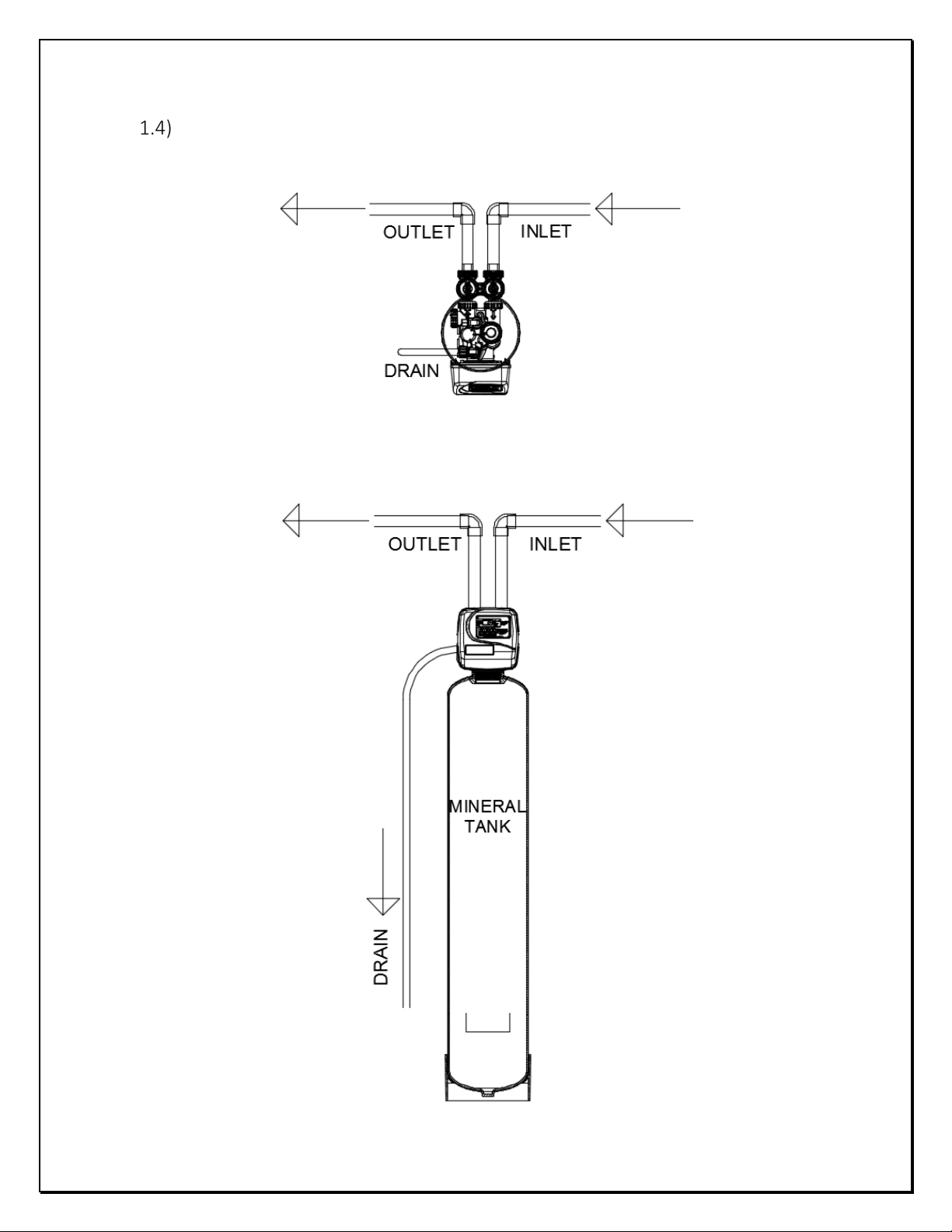
Installation Drawing
3
BARRIE ● ONTARIO ● CANADA 705.733.8900 WWW.EXCALIBURWATER.COM
FILTER INSTALLATION AND USER GUIDE
Water
Pressure
10ft
Water
Outside
Outside
Water
Cold
Cold
Hot
Hot
10ft
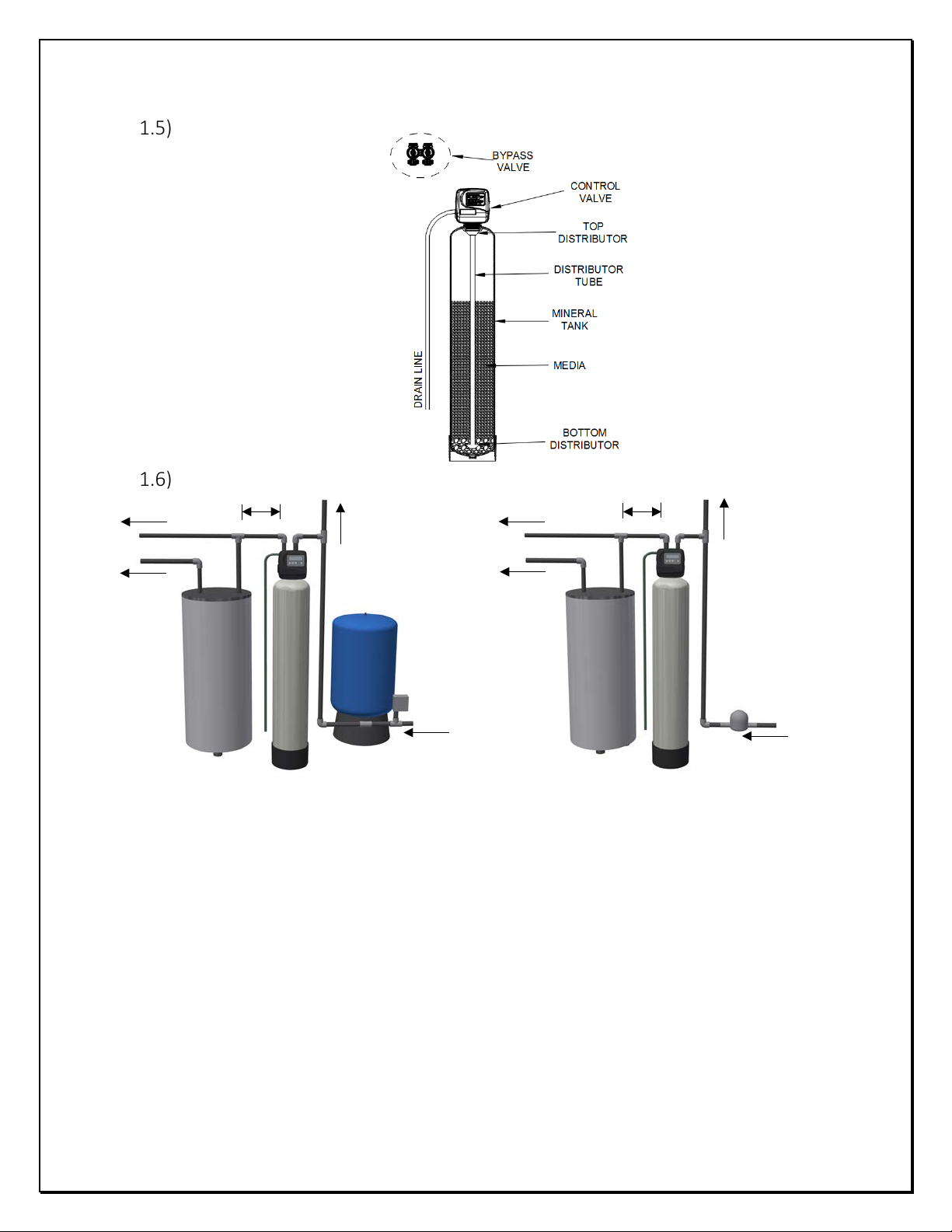
System Drawing
Plumbing Instructions
4
Tap
Tap
heater
Tank
heater
Meter
Well Water Installation Municipal Installation
1) The filter must be located at the closest possible location to drain.
2) The water heater’s inlet must be at least 10ft away from filter.
3) The unit including the drain must be located in a room temperature above 33° F.
4) If vacuum occurrence is expected then the vacuum breaker must be installed at the inlet of the
filter.
5) The bypass valve must be installed on the control valve.
6) The outside tap water if possible may be bypassed from the filter.
7) The primer, solder or solder flux must not get on the O-rings while installation.
8) After soldering the lines must be cooled before installing the O-Rings, nuts and caps.
9) If the electrical system is grounded to the plumbing, then a copper strap must be connected
between inlet and outlet as shown in figure above.
10) The plumbing must be done by following the local plumbing codes.
BARRIE ● ONTARIO ● CANADA 705.733.8900 WWW.EXCALIBURWATER.COM
FILTER INSTALLATION AND USER GUIDE
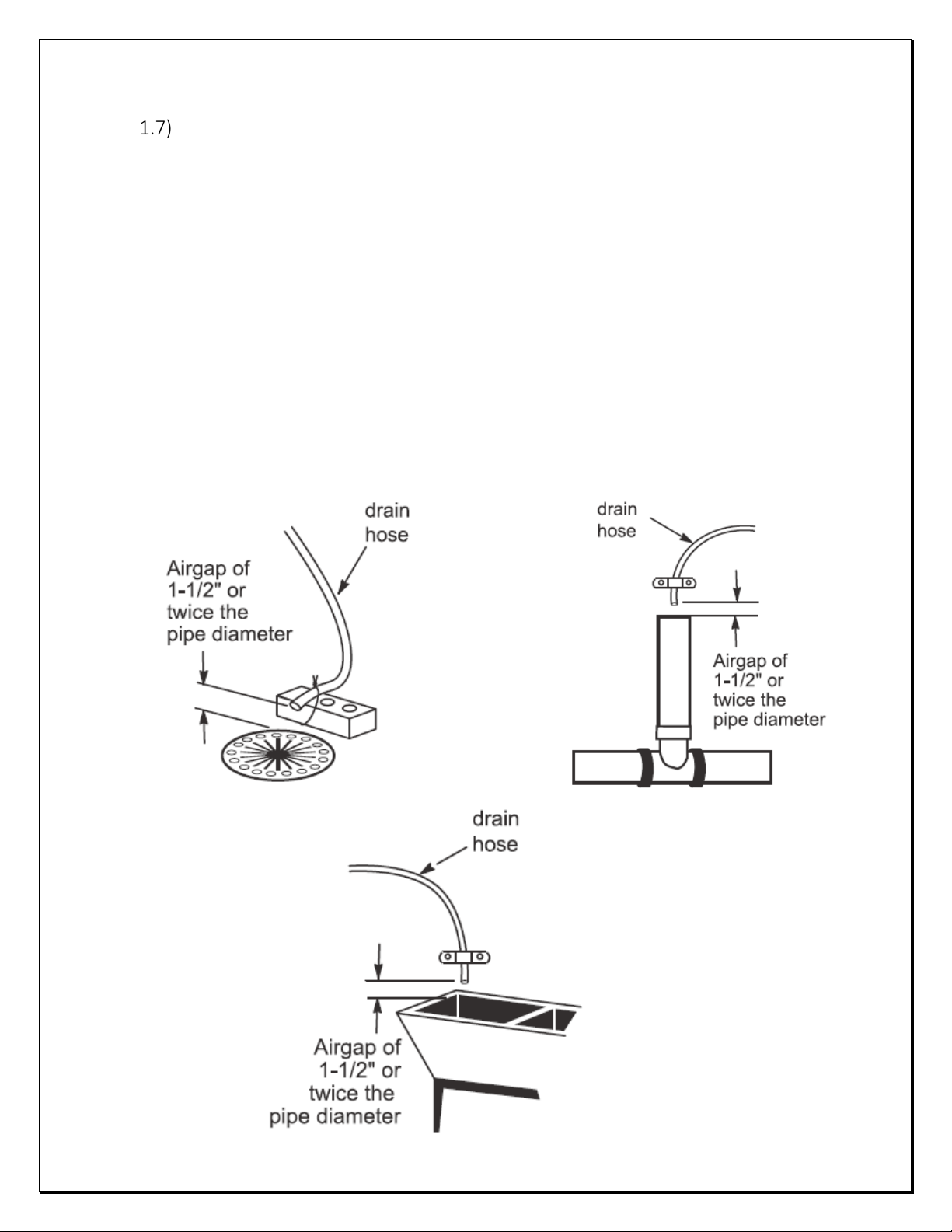
Drain Line
• The ½” tubing must be used for drain line.
• Leave minimum of 6” gap between flow control fitting and solder joints. The gap less than this
can damage the flow control.
• If the drain line is elevated and then emptied into the drain below the level the of control valve
then 7” loop should make at the end of drain line.
• The air gap between the drain and the end of the drain line must be twice the diameter of the
tube.
• The drain line must be clamped or strap tied at the end to secure in position.
5
BARRIE ● ONTARIO ● CANADA 705.733.8900 WWW.EXCALIBURWATER.COM
FILTER INSTALLATION AND USER GUIDE
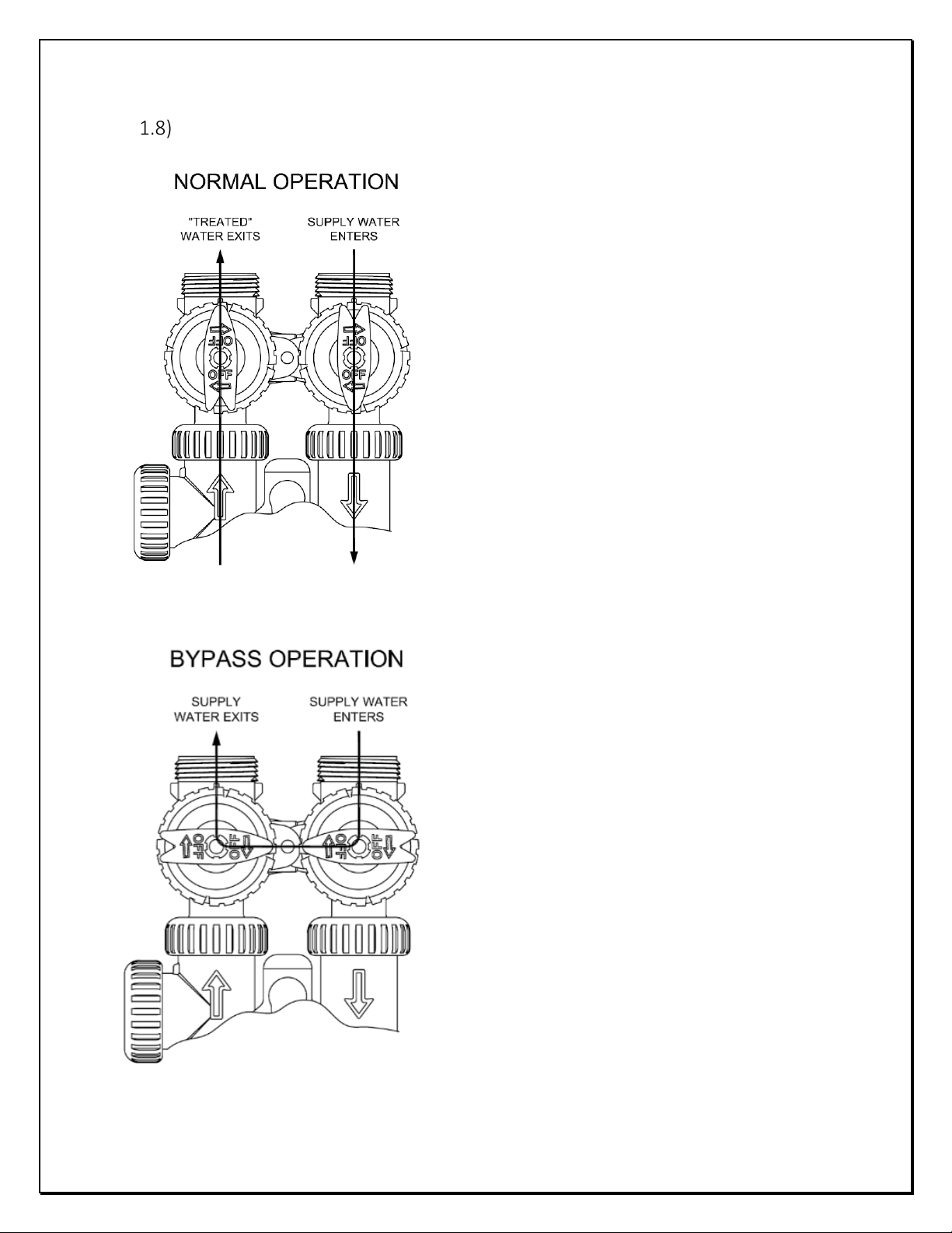
NORMAL OPERATION
BYPASS OPERATION
Bypass Valve
6
The inlet and outlet handles of bypass valve should be
pointing the direction of flow indicated by the
engraved arrows on the control valve. Water flows
through the control valve in normal operation as a
water filter.
The inlet and outlet handles point to the center of
the bypass valve. The system is isolated from the
water pressure in the plumbing system. Unfiltered
water is supplied to the house in this position.
BARRIE ● ONTARIO ● CANADA 705.733.8900 WWW.EXCALIBURWATER.COM
FILTER INSTALLATION AND USER GUIDE
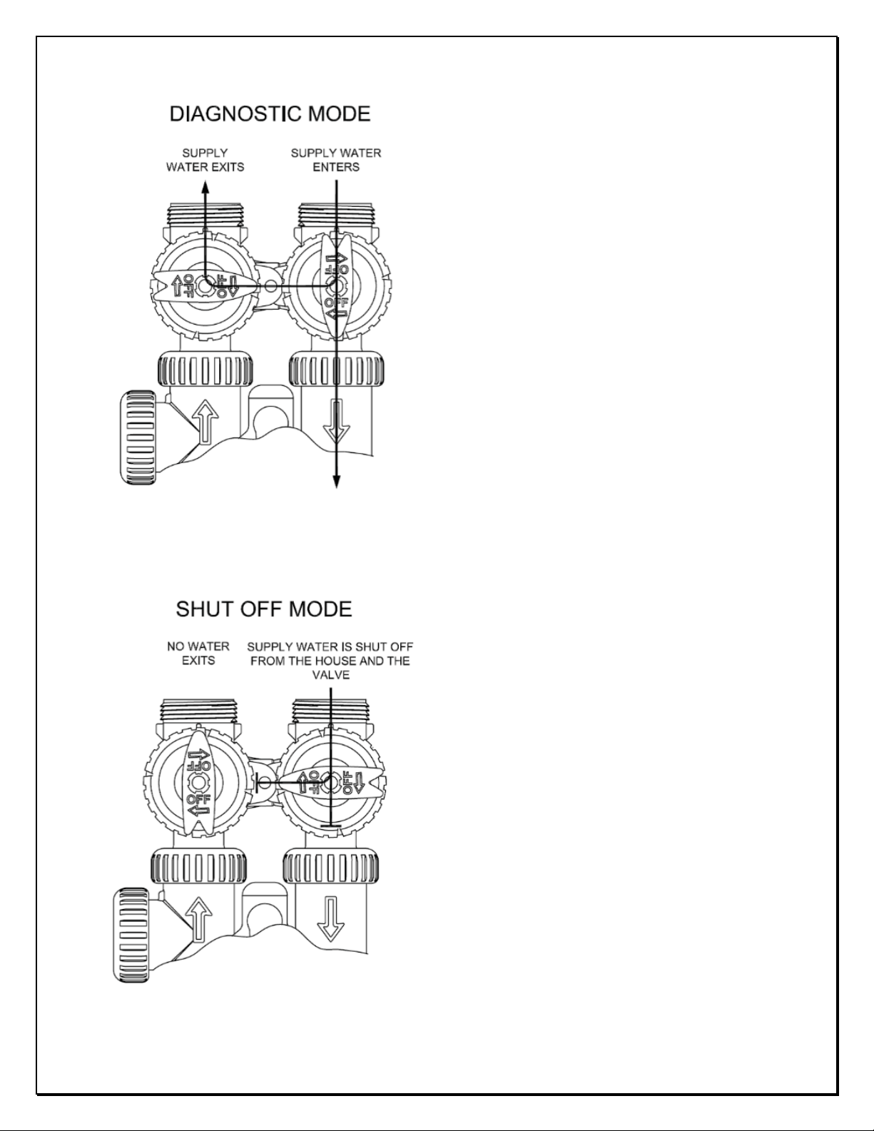
DIAGNOSTIC MODE
SHUT OFF MODE
7
The inlet handle points in the direction of flow and the
outlet handle points to the center of bypass valve,
system water pressure is allowed to the control valve
and the plumbing system while not allowing water to
exit from the control valve to the plumbing. Unfiltered
water is supplied to the house in this position.
The inlet handle points to the center of the bypass
valve and the outlet handle points in the direction of
flow, the water is shut off to the plumbing system. If
water is available on the outlet side of the Filter, it is
an indication of water bypass around the system.
BARRIE ● ONTARIO ● CANADA 705.733.8900 WWW.EXCALIBURWATER.COM

FILTER INSTALLATION AND USER GUIDE
Start Up Instructions
• Keep the bypass valve in bypass operation by moving both handles pointing towards the center
of bypass valve. Now the unfiltered water is being supplied to house. Open the faucet
downstream of the filter until water comes clear out of it. The initial water can be dirty because
of installation debris. Now inspect the leaks in plumbing.
• Press and hold the “UP” and “DOWN” buttons simultaneously for 3 seconds to start immediate
manual regeneration. The drive motor will start to reach backwash cycle and countdown time
begins (C1--). Turn the inlet bypass valve handle halfway into the direction of diagnose
8
operation. Once the steady water flows out of drain then fully turn both handles of bypass valve
into the direction of service operation.
Caution: - If water flow is too rapidly, there will be a loss of media to drain.
• When the water becomes clear in drain line then press the “UP” or “DOWN” button to advance
the regeneration to rinse cycle (C4--). Allow this process for the full amount of time during the
cycle.
• Once regeneration is finished the control valve will automatically come to the service position
with the time of day or days to next regeneration being displayed.
BARRIE ● ONTARIO ● CANADA 705.733.8900 WWW.EXCALIBURWATER.COM
FILTER INSTALLATION AND USER GUIDE
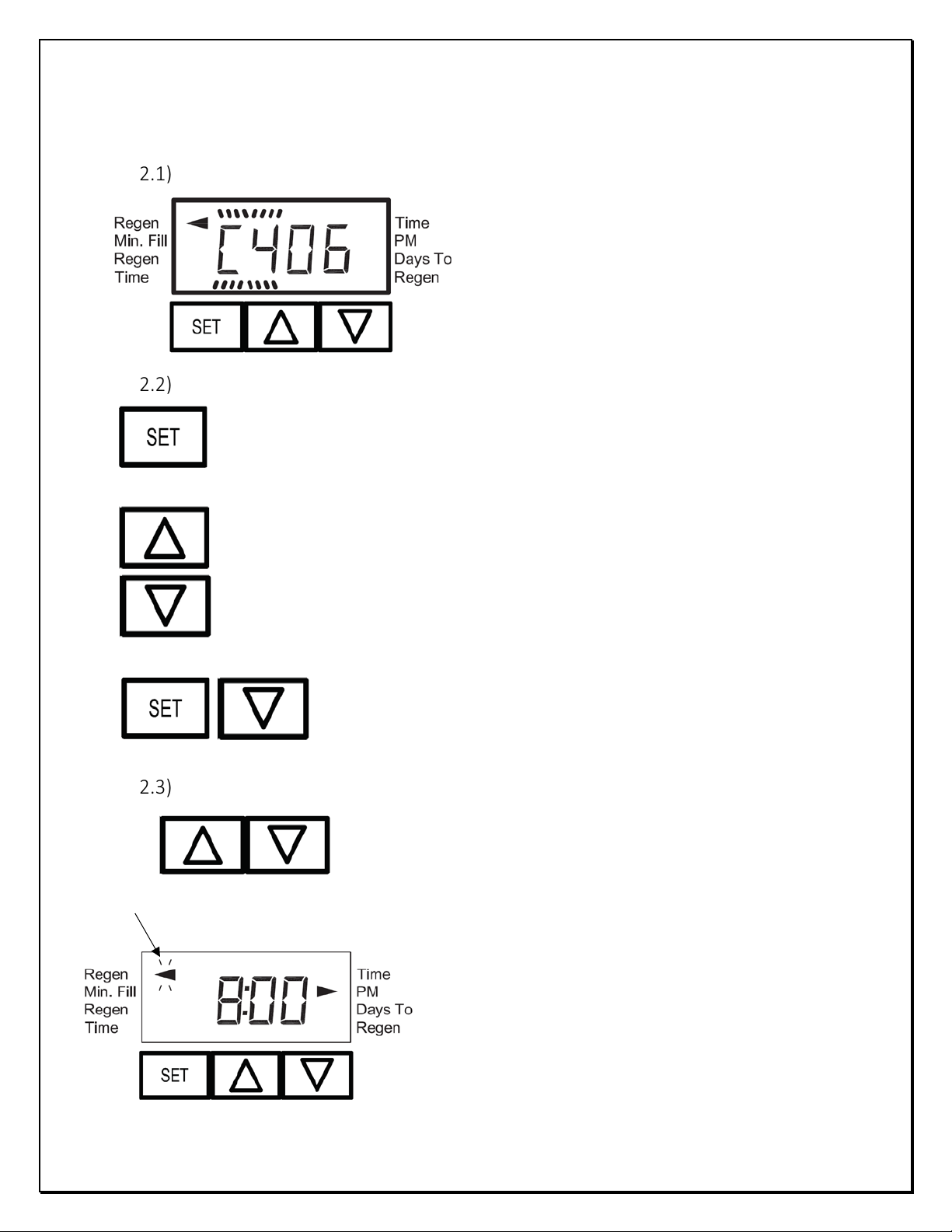
• Displays the cycle sequence number.
Regeneration Tonight: - Press ▲ and ▼ buttons once
• Change Variable being displayed.
• Advance the regeneration to next cycle
• Sets time of day
REGEN
ARROW
• Exit programming without saving
2) CONTROL VALVE PROGRAMMING
Regeneration Screens
9
• Displays the time remaining in the current cycle.
Button Operation
• Proceed to next step in settings
• Save changes and Exit to user display from any programming screen
• Scroll to the next display
• Initiate medium reset
Manual Regeneration
BARRIE ● ONTARIO ● CANADA 705.733.8900 WWW.EXCALIBURWATER.COM
and release to schedule a regeneration for preset time.
The arrow will point the word REGEN which indicates the
regeneration is expected tonight.
Press ▲ and ▼ buttons again to cancel the scheduled
regeneration for tonight.
Immediate Regeneration: - Press ▲ and ▼ buttons and
hold for 3 seconds until the control valve motor starts.
 Loading...