

Excalibur Water Systems CHLOROSOFT SERIES Installation Manual

CHLOROSOFT SERIES
ELECTRONIC METERED
WATER SOFTENER/FILTER
Installation Manual
220 Bayview Avenue Unit #18
Barrie, Ontario Canada
L4N 4Y8
www.excaliburwater.com
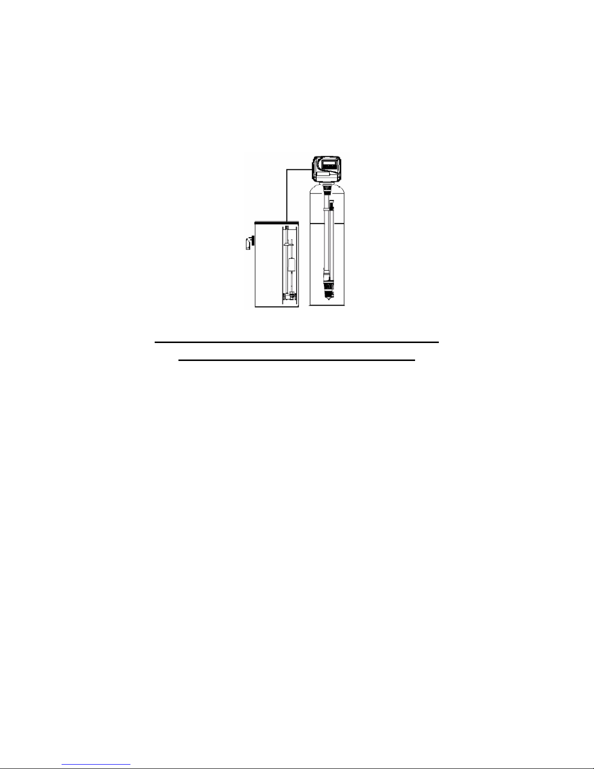
EXCALIBUR CHLOROSOFT
WATER SOFTENER/FILTER
INSTALLATION MANUAL
GENERAL WATER SOFTENER/FILTER
INSTALLATION PROCEDURES
The Water Softener/Filter control valve, fittings and/or bypass Water
Softener/Filter valve are designed to accommodate minor plumbing
misalignments that may occur during the Water Softener/Filter
installation. Do Not use Vaseline, oils or other hydrocarbon lubricants
when installing your Chlorosoft Water Softener/Filter or spray silicone
anywhere. A silicone lubricant may be used when installing your
Chlorosoft Water Softener/Filter on black o-rings but is not necessary.
Avoid any type of lubricants including silicone when installing your
Chlorosoft Water Softener/Filter on red or clear lip seals.
Do not use pipe dope or other sealants on the Water Softener/Filter
threads. Teflon tape must be used on the Water Softener/Filter
threads such as the 1 inch NPT elbow, the ¼ inch NPT connection,
and the Water Softener/Filter drain line connection. The nuts and
caps of the Chlorosoft Water Softener/Filter are designed to be
unscrewed or tightened by hand or with the special plastic Water
Softener/Filter service wrench part number V3193. If necessary,
pliers can be used to unscrew the Chlorosoft Water Softener/Filter
nut or cap. No not use a pipe wrench to tighten or loosen the
Chlorosoft Water Softener/Filter nuts or caps. Do not place
screwdriver in slots on caps and/or tap with a hammer as this could
damage the Chlorosoft Water Softener/Filter
WATER SOFTENER/FILTER/FILTER INSTALLATION
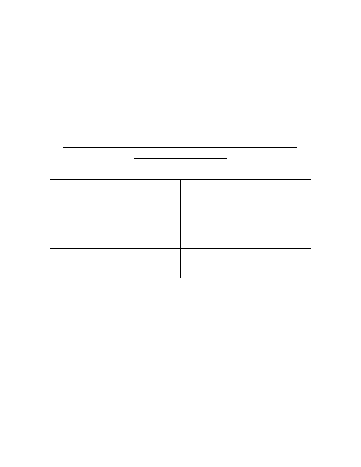
SITE REQUIRMENTS
• Water pressure 20 – 125
psi
• Water temperature 5 to
30°C or 40 to 100°F
• The Water Softener/Filter
tank should be on a firm
level surface
• Electrical use of 115/120
volt 60 Hz uninterrupted
outlet
1. The distance between the Chlorosoft Water Softener/Filter
and the water drain should be as short as possible. When
installing your Chlorosoft Water Softener/Filter all plumbing
must be done in accordance with local plumbing codes. The
Water Softener/Filter must not have a piping header that
exceeds 3 meters (10 feet).
2. Since Water Softener/Filter salt must be used periodically
and be added to the Water Softener/Filter, the brine tank
should be located where it is easily accessible.
• Current draw is 0.25 amps
• A 15 foot power cord is
furnished
• The plug-in transformer is
for dry location only
• Batteries are not used

3. Do not install your Chlorosoft Water Softener/Filter with less
than 10 feet of piping between your Water Softener/Filter
and it’s electrical outlet and the inlet of the water heater.
4. Do not locate the Chlorosoft Water Softener/Filter where it’s
connections including the Water Softener/Filter drain and
overflow plumbing will be in a room with a room temperature
under 2°C or 34°F.
5. The use of resin cleaner in your Chlorosoft Water
Softener/Filter in an unvented enclosure is not
recommended.
6. The Water Softener/Filter inlet/outlet plumbing will be
installed downstream of outdoor spigots. Install an inlet
shutoff valve and plumbing to the Water Softener/Filter
bypass valve located at the right rear as you face the Water
Softener/Filter. There are a variety of Water Softener/Filter
installation fittings available. They are listed under Water
Softener/Filter installation fitting assemblies. When
assembling the Water Softener/Filter installation fitting
package (inlet and outlet) connect the fitting to the plumbing
system first and attach the Water Softener/Filter nut, split
ring and o-ring. Heat from soldering or solvent cements may
damage the Water Softener/Filter nut, split ring or o-ring.
Solder joints should be cool and solvent cements should be
set before installing the Water Softener/Filter nut, split ring
and o-ring. Avoid getting solder flux, primer and solvent
cement on any part of the Water Softener/Filter o rings, split
rings, bypass valve or control valve. If the building electrical
system is grounded to the plumbing system, install a copper
grounding strap from the inlet to the outlet plumbing.
7. WATER SOFTENER/FILTER DRAIN LINE
First, be sure that the Water Softener/Filter drain line can
handle the flow rate of the Water Softener/Filter. Solder joints
near the drain line must be done prior to connecting the Water
Softener/Filter drain line flow control fitting. Leave at least 6
inched between the Water Softener/Filter drain line flow control
 Loading...