

Page 1

Nios Embedded Processor
Programmer’s Reference Manual
July 2001
Version 1.1.1
101 Innovation Drive
San Jose, CA 95134
(408) 544-7000
http://www.altera.com
A-MNL-NIOSPROG-01.1
Page 2

Nios Embedded Processor Programmer’s Reference Manual
Copyright 2001 Altera Corporation. Altera, The Programmable Solutions Company, the stylized Altera logo, specific device designations, and all
other words and logos that are identified as trademarks and/or service marks are unless noted otherwise, the trademarks and service marks of Altera
Corporation in the U.S. and other countries. All other product or service names are the property of their respective holders. ModelSim is a registered
trademark of Mentor Graphics Corporation. Altera products are protected under numerous U.S. and foreign patents and p ending applica tions,
maskwork rights, and copyrights. Altera warrants performance of its semiconductor products to current s pecifications in accordance with Alte ra’s
standard warranty, but reserves the right to make changes to any products and services at any time without notice. Altera assumes no responsibility
or liability arising out of the application or use of any information, product, or service described herein except as expressly agreed to in writing by
Altera Corporation. Altera customers are advised to obtain the latest version of device specifications before relying on any
published information and before placing orders for products or services. All rights reserved.
ii Altera Corporation
Page 3
About this Manual
This manual provides comprehensive information about the NiosTM
embedded processor.
The terms Nios processor or Nios embedded processor are used when
referring to the Altera soft core microprocessor in a general or abstract
context.
The term Nios CPU is used when referring to the specific block of logic, in
whole or part, that implements the Nios processor architecture.
Table 1 below shows the programmer’s reference manual revision history.
Table 1. Revision History
Revision Date Description
Version 1.1 March 2001 Nios Embedded Processor Programmer’s
Reference Manual - printed
Version 1.1.1 July 2001 PDF format
Altera Corporation iii
Page 4

About this Manual
How to Contact
For the most up-to-date information about Altera products, go to the
Altera world-wide web site at http://www.altera.com.
Altera
For additional information about Altera products, consult the sources
shown in Table 2.
Table 2. How to Contact Altera
Information Type Access USA & Canada All Other Locations
Altera Literature
Services
Non-technical
customer service
Technical support Telephone hotline (800) 800-EPLD
General product
information
Note:
(1) You can also contact your local Altera sales office or sales representative.
Electronic mail lit_req@altera.com (1) lit_req@altera.com (1)
Telephone hotline (800) SOS-EPLD (408) 544-7000
(7:30 a.m. to 5:30 p.m.
Pacific Time)
Fax (408) 544-7606 (408) 544-7606
(408) 544-7000 (1)
(6:00 a.m. to 6:00 p.m.
Pacific Time)
Fax (408) 544-6401 (408) 544-6401 (1)
Electronic mail support@altera.com support@altera.com
FTP site ftp.altera.com ftp.altera.com
Telephone (408) 544-7104 (408) 544-7104 (1)
World-wide web site http://www.altera.com http://www.altera.com
(7:30 a.m. to 5:30 p.m.
Pacific Time)
iv Altera Corporation
Page 5

GettingAbout this Manual
Typographic
The Nios Embedded Processor Programmer’s Reference Manual uses the
typographic conventions shown in Table 3.
Conventions
Table 3. Conventions
Visual Cue Meaning
Bold Type with Initial
Capital Letters
bold type External timing parameters, directory names, project names, disk drive names,
Bold italic type Book titles are shown in bold italic type with initial capital letters. Example:
Italic Type with Initial
Capital Letters
Italic type Internal timing parameters and variables are shown in italic type. Examples: tPIA, n +
Initial Capital Letters Keyboard keys and menu names are shown with initial capital letters. Examples:
“Subheading Title” References to sections within a document and titles of Quartus II and MAX+PLUS II
Courier type Signal and port names are shown in lowercase Courier type. Examples: data1, tdi,
Command names, dialog box titles, checkbox options, and dialog box options are
shown in bold, initial capital letters. Example: Save As dialog box.
filenames, filename extensions, and software utility names are shown in bold type.
Examples: f
1999 Device Data Book.
Document titles are shown in italic type with initial capital letters. Example: AN 75
(High-Speed Board Design).
1.
Variable names are enclosed in angle brackets (< >) and shown in italic type. Example:
<file name>, <project name>.pof file.
Delete key, the Options menu.
Help topics are shown in quotation marks. Example: “Configuring a FLEX 10K or FLEX
8000 Device with the BitBlaster
input. Active-low signals are denoted by suffix _n, e.g., reset_n.
, \maxplus2 directory, d: drive, chiptrip.gdf file.
MAX
™
Download Cable.”
Anything that must be typed exactly as it appears is shown in Courier type. For
example: c:\max2work\tutorial\chipt rip.gdf. Also, sections of an actual
file, such as a Report File, references to parts of files (e.g., the AHDL keyword
SUBDESIGN), as well as logic function names (e.g., TRI) are shown in Courier.
1., 2., 3., and a., b., c.,... Numbered steps are used in a list of items when the sequence of the items is
important, such as the steps listed in a procedure.
■ Bullets are used in a list of items when the sequence of the items is not important.
v
1
r
f
Altera Corporation v
The checkmark indicates a procedure that consists of one step only.
The hand points to information that requires special attention.
The angled arrow indicates you should press the Enter key.
The feet direct you to more information on a particular topic.
Page 6

Notes:
vi Altera Corporation
Page 7

Contents
Contents
How to Contact Altera ................................................................................................................... iv
Typographic Conventions...............................................................................................................v
Overview...............................................................................................1
Introduction.......................................................................................................................................1
Audience ....................................................................................................................................1
Nios CPU Overview.........................................................................................................................1
Instruction Set ...................................................................................................................................2
Register Overview ............................................................................................................................2
General-Purpose Registers ......................................................................................................2
The K Register ...........................................................................................................................4
The Program Counter...............................................................................................................4
Control Registers.......................................................................................................................4
Memory Access Overview...............................................................................................................7
Reading from Memory (or Peripherals)........................................................................8
Writing to Memory (or Peripherals) ..............................................................................9
Addressing Modes..........................................................................................................................10
5/16-bit Immediate Value .....................................................................................................10
Full Width Register-Indirect..................................................................................................12
Partial Width Register-Indirect.............................................................................................12
Full Width Register-Indirect with Offset.............................................................................13
Partial Width Register-Indirect with Offset........................................................................13
Program-Flow Control...................................................................................................................14
Relative-Branch Instructions.................................................................................................14
Absolute-Jump Instructions ..................................................................................................15
Trap Instructions.....................................................................................................................15
Conditional Instructions........................................................................................................15
Exceptions........................................................................................................................................16
Exception Handling Overview.............................................................................................16
Exception Vector Table ..........................................................................................................16
External Hardware Interrupt Sources..................................................................................17
Internal Exception Sources....................................................................................................17
Register Window Underflow ........................................................................................17
Register Window Overflow...........................................................................................18
Direct Software Exceptions (TRAP Instructions)...............................................................19
Exception Processing Sequence ............................................................................................19
Register Window Usage.................................................................................................20
Status Preservation: ISTATUS Register .......................................................................20
Return-Address.......................................................................................................................21
Simple and Complex Exception Handlers..........................................................................21
Altera Corporation vii
Altera Corporation #
Page 8

Contents
32-Bit Instruction Set .............................................................................. 33
ABS....................................................................................................................................................34
ADD ..................................................................................................................................................35
ADDI.................................................................................................................................................36
AND..................................................................................................................................................37
ANDN...............................................................................................................................................38
ASR....................................................................................................................................................39
ASRI ..................................................................................................................................................40
BGEN ................................................................................................................................................41
BR ......................................................................................................................................................42
BSR ....................................................................................................................................................43
CALL.................................................................................................................................................44
CMP .................................................................................................................................................. 45
CMPI .................................................................................................................................................46
EXT16d .............................................................................................................................................47
EXT16s ..............................................................................................................................................48
EXT8d ...............................................................................................................................................49
EXT8s ................................................................................................................................................50
FILL16...............................................................................................................................................51
FILL8.................................................................................................................................................52
IF0......................................................................................................................................................53
IF1......................................................................................................................................................54
IFRnz.................................................................................................................................................55
IFRz ..................................................................................................................................................56
IFS......................................................................................................................................................57
JMP....................................................................................................................................................58
LD......................................................................................................................................................59
LDP....................................................................................................................................................60
LDS.................................................................................................................................................... 61
LRET .................................................................................................................................................62
LSL ....................................................................................................................................................63
LSLI ...................................................................................................................................................64
LSR ....................................................................................................................................................65
LSRI...................................................................................................................................................66
MOV..................................................................................................................................................67
MOVHI.............................................................................................................................................68
MOVI ................................................................................................................................................69
MSTEP ..............................................................................................................................................70
MUL ..................................................................................................................................................71
NEG...................................................................................................................................................72
NOP...................................................................................................................................................73
NOT...................................................................................................................................................74
OR......................................................................................................................................................75
PFX ....................................................................................................................................................76
RDCTL.............................................................................................................................................. 77
RESTORE..........................................................................................................................................78
viii Altera Corporation
Page 9

Contents
RET....................................................................................................................................................79
RLC....................................................................................................................................................80
RRC ...................................................................................................................................................81
SAVE.................................................................................................................................................82
SEXT16..............................................................................................................................................83
SEXT8................................................................................................................................................84
SKP0..................................................................................................................................................85
SKP1..................................................................................................................................................86
SKPRnz.............................................................................................................................................87
SKPRz ...............................................................................................................................................88
SKPS..................................................................................................................................................89
ST.......................................................................................................................................................90
ST16d ................................................................................................................................................91
ST16s .................................................................................................................................................92
ST8d ..................................................................................................................................................93
ST8s ...................................................................................................................................................94
STP.....................................................................................................................................................95
STS.....................................................................................................................................................96
STS16s...............................................................................................................................................97
STS8s .................................................................................................................................................98
SUB....................................................................................................................................................99
SUBI ................................................................................................................................................100
SWAP..............................................................................................................................................101
TRAP...............................................................................................................................................102
TRET ...............................................................................................................................................103
WRCTL...........................................................................................................................................104
XOR.................................................................................................................................................105
Index ................................................................................................107
ix Altera Corporation
Page 10

Notes:
x Altera Corporation
Page 11

List of Tables
Table 1. Revision History............................................................................................................................ iii
Table 2. How to Contact Altera.................................................................................................................. iv
Table 3. Conventions .....................................................................................................................................v
Table 4. Nios CPU Architecture...................................................................................................................1
Table 5. Register Groups...............................................................................................................................2
Table 6. Programmer’s Model......................................................................................................................3
Table 7. Condition Code Flags .....................................................................................................................6
Table 8. Typical 32-bit Nios CPU Program/Data Memory at Address 0x0100...................................7
Table 9. N-bit-wide Peripheral at Address 0x0100 (32-bit Nios CPU)...................................................7
Table 10. Instructions Using 5/16-bit Immediate Values ........................................................................11
Table 11. Instructions Using Full Width Register-indirect Addressing.................................................12
Table 12. Instructions Using Partial Width Register-indirect Addressing ............................................12
Table 13. Instructions Using Full Width Register-indirect with Offset Addressing............................13
Table 14. Instructions Using Partial Width Register-indirect with Offset Addressing .......................14
Table 15. BR Branch Delay Slot Example.................................................................................................... 23
Table 16. Notation Details.............................................................................................................................25
Table 17. 32-bit Major Opcode Table...........................................................................................................28
Table 18. GNU Compiler/Assembler Pseudo-instructions..................................................................... 31
Altera Corporation xi
Page 12

Notes:
xii Altera Corporation
Page 13

Overview
1
Overview
Introduction
Nios CPU Overview
The NiosTM embedded processor is a soft core CPU optimized for
programmable logic and system-on-a-programmable chip (SOPC)
integration. It is a configurable, general-purpose RISC processor that can
be combined with user logic and programmed into an Altera
programmable logic device (PLD). The Nios CPU can be configured for a
wide range of applications. A 16-bit Nios CPU core running a small
program out of an on-chip ROM makes an effective sequencer or
controller, taking the place of a hard-coded state machine. A 32-bit Nios
CPU core with external FLASH program storage and large external main
memory is a powerful 32-bit embedded processor system.
Audience
This reference manual is for software and hardware engineers creating
system design modules using the Excalibur Development Kit, featuring
the Nios embedded processor. This manual assumes you are familiar with
electronics, microprocessors, and assembly language programming. To
become familiar with the conventions used with the Nios CPU, see
Table 16 on page 25.
The Nios CPU is a pipelined, single-issue RISC processor in which most
instructions run in a single clock cycle. The Nios instruction set is targeted
for compiled embedded applications. The 16-bit and 32-bit Nios CPU
have native-word sizes of 16 bits and 32 bits, respectively, meaning the
16-bit Nios CPU has a native-word size of a half-word, while the 32-bit
Nios CPU has a native-word size of a word. In Nios, byte refers to an 8-bit
quantity, half-word refers to a 16-bit quantity, and word refers to a 32-bit
quantity. The Nios family of soft core processors includes 32-bit and 16-bit
architecture variants.
Table 4. Nios CPU Architecture
Nios CPU Details 32-bit Nios CPU 16-bit Nios CPU
Data bus size (bits) 32 16
ALU width (bits) 32 16
Internal register width (bits) 32 16
Address bus size (bits) 33 17
Instruction size (bits) 16 16
Logic cells (typical) 1700 1100
f
(EP20K200E –1) Up to 50MHz Up to 50MHz
max
Altera Corporation 1
Page 14

Overview
The Nios CPU ships with the GNUPro compiler and debugger from
Cygnus, an industry-standard open-source C/C++ compiler, linker and
debugger toolkit. The GNUPro toolkit includes a C/C++ compiler, macroassembler, linker, debugger, binary utilities, and libraries.
Instruction Set
Register Overview
The Nios instruction set is tailored to support programs compiled from C
and C++. It includes a standard set of arithmetic and logical operations,
and instruction support for bit operations, byte extraction, data
movement, control flow modification, and conditionally executed
instructions, which can be useful in eliminating short conditional
branches.
This section describes the organization of the Nios CPU general-purpose
registers and control registers. The Nios CPU architecture has a large
general-purpose register file, several machine-control registers, a
program counter, and the K register used for instruction prefixing.
General-Purpose Registers
The general-purpose registers are 32 bits wide in the 32-bit Nios CPU and
16 bits wide in the 16-bit Nios CPU. The register file size is configurable
and contains a total of either 128, 256, or 512 registers. The software can
access the registers using a 32-register-long sliding window that moves
with a 16-register granularity. This sliding window can traverse the entire
register file. This sliding window provides access to a subset of the
register file.
The register window is divided into four even sections as shown in
Table 5. The lowest eight registers (%r0-%r7) are global registers, also
known as %g0-%g7. These global registers do not change with the
movement or position of the window, but remain accessible as
(%g0-%g7). The top 24 registers (%r8-%r31) in the register file are
accessible through the current window.
Table 5. Register Groups
In registers %r24-%r31 or %i0-%i7
Local registers %r16-%r23 or %L0-%L7
Out registers %r8-%r15 or %o0-%o7
Global registers %r0-%r7 or %g0-%g7
The top eight registers (%i0-%i7) are known as in registers, the next eight
(%L0-%L7) as local registers, and the other eight (%o0-%o7) are known as
out registers. When a register window moves down 16-registers (as it does
for a SAVE instruction), the out registers become the in registers of the
new window position. Also, the local and in registers of the last window
position become inaccessible. See Table 6 for more detailed information.
2 Altera Corporation
Page 15
.
Table 6. Programmer’s Model
31 16 15
%i7 %r31 SAVED return-address
%i6 %r30 %fp—frame pointer
%i5 %r29
I
%i4 %r28
N
%i3 %r27
%i2 %r26
%i1 %r25
%i0 %r24
%L7 %r23
%L6 %r22
L
%L5 %r21
O
%L4 %r20
C
%L3 %r19
A
%L2 %r18
L
%L1 %r17
%L0 %r16
%o7 %r15 current return-address
%o6 %r14
%o5 %r13
O
%o4 %r12
U
%o3 %r11
T
%o2 %r10
%o1 %r9
%o0 %r8
%g7 %r7
G
%g6 %r6
L
%g5 %r5
O
%g4 %r4
B
%g3 %r3
A
%g2 %r2
L
%g1 %r1
%g0 %r0
Base-pointer 3 for STP/LDP (or general-purpose local)
Base-pointer 2 for STP/LDP (or general-purpose local)
Base-pointer 1 for STP/LDP (or general-purpose local)
Base-pointer 0 for STP/LDP (or general-purpose local)
%sp-Stack Pointer
GettingOverview
1
0
Overview
109876543210
32 31
PC
%ctl9 CLR_IE Any write (WRCTL) operation to this register sets STATUS[15] (IE)=0. Result of any read-operation (RCTL)
is undefined.
%ctl8 SET_IE Any write (WRCTL) operation to this register sets STATUS[15] (IE)=1. Result of any read-operation (RCTL)
is undefined.
%ctl7 —— reserved —
%ctl6 —— reserved —
%ctl5 —— reserved —
%ctl4 —— reserved —
%ctl3 —— reserved —
%ctl2 WVALID HI_LIMIT LO_LIMIT
%ctl1 ISTATUS Saved Status
%ctl0 STATUS IE IPRI CWP N V Z C
K REGISTER
16 15 109876543210
Altera Corporation 3
Page 16

Overview
The K Register
The K register is an 11-bit prefix value and is always set to 0 by every
instruction except PFX. A PFX instruction sets K directly from the IMM11
instruction field. Register K contains a non-zero value only for an
instruction immediately following PFX.
A PFX instruction disables interrupts for one cycle, so the two-instruction
PFX sequence is an atomic CPU operation. Also, PFX sequence instruction
pairs are skipped together by SKP-type conditional instructions.
The K register is not directly accessed by software, but is used indirectly.
A MOVI instruction, for example, transfers all 11 bits of K into bits 15..5 of
the destination register. This K-reading operation will only yield a nonzero result when the previous instruction is PFX.
The Program Counter
The program counter (PC) register contains the byte-address of the
currently executing instruction. Since all instructions must be half-wordaligned, the least-significant bit of the PC value is always 0.
The PC increments by tw o (PC ← PC + 2) after every instruction unless the
PC is explicitly set. The following instructions modify PC directly: BR,
BSR, CALL, JMP, LRET, RET and TRET. The PC is 33-bits wide in a 32-bit
Nios CPU and 17-bits wide in a 16-bit Nios CPU.
Control Registers
There are five defined control registers that are addressed independently
from the general-purpose registers. The RDCTL and WRCTL instructions
are the only instructions that can read or write to these control registers
(meaning %ctl0 is unrelated to %g0).
STATUS (%ctl0)
1514131211109876543210
IE IPRI CWP N V Z C
4 Altera Corporation
Page 17

GettingOverview
Interrrupt Enable (IE)
IE is the interrupt enable bit. When IE=1, it enables external interrupts and
internal exceptions. IE=0 disables external interrupts and exceptions.
Software TRAP instructions will still execute normally even when IE=0.
Note that IE can be set directly without affecting the rest of the STATUS
register by writing to the SET_IE (%ctl9) and CLR_IE (%ctl8) control
registers. When the CPU is reset, IE is set to 0 (interrupts disabled).
Interrupt Priority (IPRI)
IPRI contains the current running interrupt priority. When an exception is
processed, the IPRI value is set to the exception number. See “Exceptions”
on page 16 for more information. For external hardware interrupts, the
IPRI value is set directly from the 6-bit hardware interrupt number. For
TRAP instructions, the IPRI field is set directly from the IMM6 field of
the instruction. For internal exceptions, the IPRI field is set from the
pre-defined 6-bit exception number.
A hardware interrupt is not processed if its internal number is greater
than or equal to IPRI or IE=0. A TRAP instruction is processed
unconditionally. When the CPU is reset, IPRI is set to 63 (lowest-priority).
IPRI disables interrupts above a certain number. For example, if IPRI is 3,
then interrupts 0, 1 and 2 will be processed, but all others (interrupts 3-63)
are disabled.
Current Window Pointer (CWP)
1
Overview
CWP points to the base of the sliding register window in the generalpurpose register file. Incrementing CWP moves the register window up 16
registers. Decrementing CWP moves the register window down 16
registers. CWP is decremented by SAVE instructions and incremented by
RESTORE instructions.
Only specialized system software such as register window-management
facilities should directly write values to CWP through WRCTL. Software
will normally modify CWP by using SAVE and RESTORE instructions.
When the CPU is reset, CWP is set to the largest valid value, HI_LIMIT.
This means in a 256 register file size, there will be 16 register windows.
After reset, the WVALID register (%ct12) is set to 0x01C1, i.e., LO_LIMIT
= 1 and HI_ LIMIT =14. See “WVALID (%ctl2)” on page 6 for more
information.
Altera Corporation 5
Page 18
Overview
Condition Code Flags
Some instructions modify the condition code flags. These flags are the
four least significant bits of the status register as shown in Table 7.
Table 7. Condition Code Flags
N Sign of result, or most significant bit
V Arithmetic overflow—set if bit 31 of 32-bit result is different from
sign of result computed with unlimited precision.
ZResult is 0
C Carry-out of addition, borrow-out of subtraction
ISTATUS (%ctl1)
1514131211109876543210
ISTATUS is the saved copy of the STATUS register. When an exception is
processed, the value of the STATUS register is copied into the ISTATUS
register. This action allows the pre-exception value of the STATUS
register to be restored before control returns to the interrupted program.
See “Exceptions” on page 16 for more information. A return-from-trap
(TRET) instruction automatically copies the ISTATUS register into the
STATUS register. Interrupts are disabled (IE=0) when an exception is
processed. Before re-enabling interrupts, an exception handler must
preserve the value of the ISTATUS register. When the CPU is reset,
ISTATUS is set to 0.
WVALID (%ctl2)
1514131211109876543210
HI_LIMIT LO_LIMIT
WVALID contains two values, HI_LIMIT and LOW_LIMIT. When a
SAVE instruction decrements CWP from LOW_LIMIT to LOW_LIMIT –1
a register window underflow (exception #1) is generated. When a
RESTORE instruction increments CWP from HI_LIMIT to HI_LIMIT +1, a
register window overflow (exception #2) is generated. WVALID is
configurable and may be read-only or read/write. When the CPU is reset,
LO_LIMIT is set to 1 and HI_LIMIT is set to the highest valid window
pointer ((register file size / 16) – 2).
6 Altera Corporation
Page 19

GettingOverview
Memory Access Overview
CLR_IE(%ctl8)
Any WRCTL operation to the CLR_IE register clears the IE bit in the
STATUS register (IE ← 0) and the WRCTL value is ignored. A RDCTL
operation from CLR_IE produces an undefined result.
SET_IE (%ctl9)
Any WRCTL operation to the SET_IE register sets the IE bit in the STATUS
register (IE ← 1) and the WRCTL value is ignored. A RDCTL operation
from SET_IE produces an undefined result.
The Nios processor is little-endian. Data memory must occupy contiguous
native-words. If the physical memory device is narrower than the nativeword size, then the data bus should implement dynamic-bus sizing to
simulate full-width data to the Nios CPU. Peripherals present their
registers as native-word widths, padded by 0s in the most significant bits
if the registers happen to be smaller than native-words. Table 8 and
Table 9 show examples of the 32-bit Nios CPU native-word widths.
Table 8. Typical 32-bit Nios CPU Program/Data Memory at Address 0x0100
Address Contents
31 24 23 16 15 8 7 0
0x0100 byte 3 byte 2 byte 1 byte 0
0x0104 byte 7 byte 6 byte 5 byte 4
0x0108 byte 11 byte 10 byte 9 byte 8
0x010c byte 15 byte 14 byte 13 byte 12
1
Overview
Table 9. N-bit-wide Peripheral at Address 0x0100 (32-bit Nios CPU)
Address Contents
31 N N-1 0
0x0100 (zero padding) register 0
0x0104 (zero padding) register 1
0x0108 (zero padding) register 2
0x010c (zero padding) register 3
Altera Corporation 7
Page 20

Overview
Reading from Memory (or Peripherals)
The Nios CPU can only perform aligned memory accesses. A 32-bit read
operation can only read a full word starting at a byte address that is a
multiple of 4. A 16-bit read operation can only read a half-word starting at
a byte address that is a multiple of 2. Instructions which read from
memory always treat the low bit (16-bit Nios CPU) or low two bits (32-bit
Nios CPU) of the address as 0. Instructions are provided for extracting
particular bytes and half-words from words.
The simplest instruction that reads data from memory is the LD
instruction. A typical example of this instruction is
first register operand, %g3, is the destination register, where data will be
loaded. The second register operand specifies a register containing an
address to read from. This address will be aligned to the nearest half-word
(16-bit Nios CPU) or word (32-bit Nios CPU) meaning the lowest bit (16bit Nios CPU) or two bits (32-bit Nios CPU) will be treated as if they are 0.
Quite often, however, software must read data smaller than the native
data size. The Nios CPU provides instructions for extracting individual
bytes (16-bit and 32-bit Nios CPU) and half-words (32-bit Nios CPU) from
native-words. The EXT8d instruction is used for extracting a byte, and the
EXT16d instruction is used for extracting a word. A typical example of the
EXT8d instruction is EXT8d %g3,%o4. The EXT8d instruction uses the
lowest bit (on 16-bit Nios CPU) or two bits (on 32-bit Nios CPU) of the
second register operand to extract a byte from the first register operand,
and replace the entire contents of the first register operand with that byte.
LD %g3, [%o4]. The
The assembly-language example in Code Example 1 shows how to read a
single byte from memory, even if the address of the byte is not nativeword-aligned.
Code Example 1: Reading a Single Byte from Memory
Contents of memory:
; 0 1 2 3
; 0x00001200 0x46 0x49 0 x53 0x48
;Instructions executed on a 32-bit Nios CPU
x00001202
LD %g3,[%o4] ; %g3 gets the contents of address 0x1200,
EXT8d %g3,%o4 ; %g3 gets replaced with byte 2 fro m %g3,
8 Altera Corporation
; Let’s assume %o4 contains the add ress
; so %g3 contains 0x48534946
; so %g3 contains 0x00000053
Page 21

GettingOverview
Writing to Memory (or Peripherals)
The Nios CPU can perform aligned writes to memory in widths of byte,
half-word, or word (only the 32-bit Nios CPU can write a word). A word
(32-bit Nios CPU) can be written to any address that is a multiple of 4 in
one instruction. A half-word can be written to any address that is a
multiple of 2 in one instruction (16-bit Nios CPU) or two instructions
(32-bit Nios CPU). A byte can be written to any address in two
instructions.
On the 32-bit Nios CPU, the lowest byte of a register can be written only
to an address that is a multiple of 4; the middle-low byte of a register can
be written only as an address that is a multiple of 4, plus 1, and so on.
Similarly, on the 16-bit Nios CPU, the low byte of a register can be written
only to an even address and the high byte of a register can only be written
to an odd address.
The 32-bit Nios CPU can also write the low half-word of a register to an
address that is a multiple of four, and the high half-word of a register to
an address which is a multiple of 4, plus 2.
The ST instruction writes a full native-word to a native-word aligned
memory address from any register; the ST8d and ST16d (32-bit Nios CPU
only) instructions write a byte and half-word, respectively, with the
alignment constraints described above, from register %r0.
Often it is necessary for software to write a particular byte or half-word to
an arbitrary location in memory. The position within the source register
may not happen to correspond with the location in memory to be written.
The FILL8 and FILL16 (32-bit Nios CPU only) instructions will take the
lowest byte or half-word, respectively, of a register and replicate it across
register %r0.
1
Overview
Altera Corporation 9
Page 22

Overview
Code Example 2 shows how to write a single byte to memory, even if the
address of the byte is not native-word-aligned.
Code Example 2: Single Byte Written to Memory—Address is not Native-word-aligned
Instructions executed on a 32-bit Nios CPU
;Let’s assume %o4 contains the address 0x00001203
; and that %g3 contains the value 0x00000054
FILL8 %r0,%g3 ; (First operand can only be %r0)
ST8d [%o4],%r0 ; (Second operand can only be %r0)
Contents of memory after:
0 1 2 3
0x00001200 0x46 0x49 0x53 0x54
; replicate low byte of %g3 across %r0
; so %r0 contains 0x54545454
; Stores the 3rd byte of %r0 to address 0x1203
Addressing Modes
The topics in this section includes a description of the following
addressing modes:
■ 5/16-bit immediate
■ Full width register-indirect
■ Partial width register-indirect
■ Full width register-indirect with offset
■ Partial width register-indirect with offset
5/16-bit Immediate Value
Many arithmetic and logical instructions take a 5-bit immediate value as
an operand. The ADDI instruction, for example, has two operands: a
register and a 5-bit immediate value. A 5-bit immediate value represents
a constant from 0 to 31. To specify a constant value that requires from 6 to
16 bits (a number from 32 to 65535), the 11-bit K register can be set using
the PFX instruction, This value is concatenated with the 5-bit immediate
value. The PFX instruction must be used directly before the instruction it
modifies.
To support breaking 16-bit immediate constants into a PFX value and a
5-bit immediate value, the assembler provides the operators %hi() and
%lo(). %hi(x) extracts the 11 bits from bit 5 to bit 15 from constant x, and
%lo(x) extracts the 5 bits from bit 0 to bit 4 from constant x.
10 Altera Corporation
Page 23

GettingOverview
The following example shows an ADDI instruction being used both with
and without a PFX.
Code Example 3: The ADDI Instruction Used with/without a PFX
; Assume %g3 contains the value 0x0041
ADDI %g3,5 ; Add 5 to %g3
; so %g3 now contains 0x0046
PFX %hi(0x1234) ; Load K with upper 11 bits of 0x1234
ADDI %g3,%lo(0x1234) ; Add low 5 bits of 0x1234 to %g3
; so the K register contained 0x0091
; and the immediate operand of the ADDI
; instruction contained 0x0011, which
; concatenated together make 0x1234
Besides arithmetic and logical instructions, several other instructions use
immediate-mode constants of various widths, and the constant is not
modified by the K register. See the description of each instruction in the
“32-Bit Instruction Set” for a precise explanation of its operation. Table 10
shows instructions using 5/16-bit immediate values.
Table 10. Instructions Using 5/16-bit Immediate Values
ADDI AND* ANDN* ASRI
CMPI LSLI LSRI MOVI
MOVHI OR* SUBI XOR*
1
Overview
* AND, ANDN, OR, and XOR can only use PFX’d 16-bit immediate
values. These instructions act on two register operands if not preceded by
a PFX instruction.
Altera Corporation 11
Page 24

Overview
Full Width Register-Indirect
The LD and ST instructions can load and store, respectively, a full nativeword to or from a register using another register to specify the address.
The address is first aligned downward to a native-word aligned address,
as described in the “Memory Access Overview” section. The K register is
treated as a signed offset, in native words, from the native-word aligned
value of the address register.
Table 11. Instructions Using Full Width Register-indirect Addressing
Instruction Address Register Data Register
LD Any Any
ST Any Any
Partial Width Register-Indirect
There are no instructions that read a partial word. To read a partial word,
you must combine a full width register-indirect read instruction with an
extraction instruction, EXT8d, EXT8s, EXT16d (32-bit Nios CPU only) or
EXT16s (32-bit Nios CPU only).
Several instructions can write a partial word. Each of these instructions
has a static and a dynamic variant. The position within both the source
register and the native-word of memory is determined by the low bits of
an addressing register. In the case of a static variant, the position within
both the source register and the native-word of memory is determined by
a 1- or 2-bit immediate operand to the instruction. As with full width
register-indirect addressing, the K register is treated as a signed offset in
native words from the native-word aligned value of the address register.
The partial width register-indirect instructions all use %r0 as the source of
data to write. These instructions are convenient to use in conjunction with
the FILL8 or FILL16 (32-bit Nios CPU only) instructions.
Table 12. Instructions Using Partial Width Register-indirect Addressing
Instruction Address Register Data Register Byte/Half-word Selection
ST8s Any %r0 Immediate
ST16s* Any %r0 Immediate
ST8d Any %r0 Low bits of address register
ST16d* Any %r0 Low bits of address register
* 32-bit Nios CPU only
12 Altera Corporation
Page 25

GettingOverview
Full Width Register-Indirect with Offset
The LDP, LDS, STP and STS instructions can load or store a full nativeword to or from a register using another register to specify an address,
and an immediate value to specify an offset, in native words, from that
address.
Unlike the LD and ST instructions, which can use any register to specify a
memory address, these instructions may each only use particular registers
for their address. The LDP and STP instructions may each only use the
register %L0, %L1, %L2, or %L3 for their address registers. The LDS and
STS instructions may only use the stack pointer, register %sp (equivalent
to %o6), as their address register. These instructions each take a signed
immediate index value that specifies an offset in native words from the
aligned address pointed in the address register.
Table 13. Instructions Using Full Width Register-indirect with Offset Addressing
Instruction Address Register Data Register Offset Range without PFX
LDP %L0, %L1, %L2, %L3 Any -16..15 native-words
LDS %sp Any 0..255 native-words
STP %L0, %L1, %L2, %L3 Any -16..15 native-words
STS %sp Any 0..255 native-words
Partial Width Register-Indirect with Offset
1
Overview
There are no instructions that read a partial word from memory. To read
a partial word, you must combine a full width indexed register-indirect
read instruction with an extraction instruction, EXT8d, EXT8s, EXT16d
(32-bit Nios CPU only) or EXT16s (32-bit Nios CPU only). The STS8s and
STS16s (Nios 32 only) use an immediate constant to specify a byte or halfword offset, respectively, from the stack pointer to write the
correspondingly aligned partial width of the source register %r0.
Altera Corporation 13
Page 26

Overview
These instructions may each only use the stack pointer, register %sp
(equivalent to %o6), as their address register, and may only use register
%r0 (equivalent to %g0, but must be called %r0 in the assembly
instruction) as the data register. These instructions are convenient to use
with the FILL8 or FILL16 (32-bit Nios CPU only) instructions.
Table 14. Instructions Using Partial Width Register-indirect with Offset Addressing
Instruction Address
Register
STS8s %sp %r0 Immediate 0..1023 bytes
STS16s* %sp %r0 Immediate 0..511 half-words
Program-Flow Control
Data Register Byte/Half-word
Selection
*32-bit Nios CPU only
The topics in this section includes a description of the following:
■ Two relative-branch instructions (BR and BSR)
■ Two absolute-jump instructions (JMP and CALL)
■ Two trap instructions (TRET and TRAP)
■ Five conditional instructions (SKP, SKP0, SKP1, SKPRz and SKPRnz)
Index Range
Relative-Branch Instructions
There are two relative-branch instructions: BR and BSR. The branch target
address is computed from the current program-counter (i.e. the address of
the BR instruction itself) and the IMM11 instruction field. Details of the
branch-offset computation are provided in the description of the BR and
BSR instructions. See “BR” on page 42 and “BSR” on page 43. BSR is
identical to BR except that the return-address is saved in %o7. Details of
the return-address computation are provided in the description of the BSR
instruction. Both BR and BSR are unconditional. Conditional branches are
implemented by preceding BR or BSR with a SKP-type instruction.
Both BR and BSR instructions have branch delay slot behavior: The
instruction immediately following a BR or BSR is executed after BR or
BSR, but before the instruction at the branch-target. See “Branch Delay
Slots” on page 23 for more information. The branch range of the BR and
BSR instructions is forward by 2048 bytes, or backwards by 2046 bytes
relative to the address of the BR or BSR instruction.
14 Altera Corporation
Page 27

GettingOverview
Absolute-Jump Instructions
There are two absolute (computed) jump instructions: JMP and CALL.
The jump-target address is given by the contents of a general-purpose
register. The register contents are left-shifted by one and transferred into
the PC. CALL is identical to JMP except that the return-address is saved
in %o7. Details of the return-address computation are provided in the
description of the CALL instruction. Both JMP and CALL are
unconditional. Conditional jumps are implemented by preceding JMP or
CALL with a SKP-type instruction.
Both JMP and CALL instructions have branch delay slot behavior: The
instruction immediately following a JMP or CALL is executed after JMP
or CALL, but before the instruction at the jump-target. The LRET pseudoinstruction, which is an assembler alias for JMP %o7, is conventionally
used to return from subroutines.
Trap Instructions
The Nios processor implements two instructions for software exception
processing: TRAP and TRET. See “TRAP” on page 102 and “TRET” on
page 103 for detailed descriptions of both these instructions. Unlike JMP
and CALL, neither TRAP nor TRET has a branch delay-slot: The
instruction immediately following TRAP is not executed until the
exception-handler returns. The instruction immediately following TRET
is not executed at all as part of TRET's operation.
1
Overview
Conditional Instructions
There are five conditional instructions (SKPs, SKP0, SKP1, SKPRz, and
SKPRnz). Each of these instructions has a converse assembler-alias
pseudo-instruction (IFs, IF0, IF1, IFRz, and IFRnz, respectively). Each of
these instructions tests a CPU-internal condition and then executes the
next instruction or not, depending on the outcome. The operation of all
five SKP-type instructions (and their pseudo-instruction aliases), are
identical except for the particular test performed. In each case, the
subsequent (conditionalized) instruction is fetched from memory
regardless of the test outcome. Depending on the outcome of the test, the
subsequent instruction is either executed or cancelled.
While SKP and IF type conditional instructions are often used to
conditionalize jump (JMP, CALL) and branch (BR, BSR) instructions, they
can be used to conditionalize any instruction. Conditionalized PFX
instructions (PFX immediately after a SKPx or IFx instruction) present a
special case; the next two instructions are either both cancelled or both
executed. PFX instruction pairs are conditionalized as an atomic unit.
Altera Corporation 15
Page 28

Overview
Exceptions
The topics in this section include a description of the following:
■ Exception vector table
■ How external hardware interrupts, internal exceptions, register
window underflow, register window overflow and TRAP
instructions are handled
■ Direct software exceptions (TRAP) and exception processing
sequence
Exception Handling Overview
The Nios processor allows up to 64 vectored exceptions. Exceptions can be
enabled or disabled globally by the IE control-bit in the STATUS register,
or selectively enabled on a priority basis by the IPRI field in the STATUS
register. Exceptions can be generated from any of three sources: external
hardware interrupts, internal exceptions or explicit software TRAP
instructions.
The Nios exception-processing model allows precise handling of all
internally generated exceptions. That is, the exception-transfer
mechanism leaves the exception-handling subroutine with enough
information to restore the status of the interrupted program as if nothing
had happened. Internal exceptions are generated if a SAVE or RESTORE
instruction causes a register-window underflow or overflow,
respectively.
Exception-handling subroutines always execute in a newly opened
register window, allowing very low interrupt latency. The exception
handler does not need to manually preserve the interruptee’s register
contents.
Exception Vector Table
The exception vector table is a set of 64 exception-handler addresses. On a
32-bit Nios CPU each entry is 4 bytes and on a 16-bit Nios CPU each entry
is 2 bytes. The base-address of the exception vector table is configurable.
When the Nios CPU processes exception number n, it fetches the nth entry
from the exception vector table, doubles the fetched value and then loads
the results into the PC.
The exception vector table can physically reside in RAM or ROM,
depending on the hardware memory map of the target system. A ROM
exception vector table will not require run-time initialization.
16 Altera Corporation
Page 29

GettingOverview
External Hardware Interrupt Sources
An external source can request a hardware interrupt by driving a 6-bit
interrupt number on the Nios CPU irq_number inputs while
simultaneously asserting true (1) the Nios CPU irq input pin. The Nios
CPU will process the indicated exception if the IE bit is true (1) and the
requested interrupt number is smaller than (higher priority than) the
current value in the IPRI field of the STATUS register. Control is
transferred to the exception handler whose number is given by the
irq_number inputs.
External logic for producing the irq_number input and for driving the irq
input pin is automatically generated by the Nios SOPC builder software
and included in the peripheral bus module PBM outside the CPU. An
interrupt-capable peripheral need only generate one or more interruptrequest signals that are combined within the PBM to produce the Nios
irq_number and irq inputs.
The Nios irq input is level sensitive. The irq and irq_number inputs are
sampled at the rising edge of each clock. External sources that generate
interrupts should assert their irq output signals until the interrupt is
acknowledged by software (e.g. by writing a register inside the
interrupting peripheral to 0). Interrupts that are asserted and then deasserted before the Nios CPU core can begin processing the exception are
ignored.
Internal Exception Sources
1
Overview
There are two sources of internal exceptions: register window-overflow
and register window-underflow. The Nios processor architecture allows
precise exception handling for all internally generated exceptions. In each
case, it is possible for the exception handler to fix the exceptional
condition and make it behave as if the exception-generating instruction
had succeeded.
Register Window Underflow
A register window underflow exception occurs whenever the lowest valid
register window is in use (CWP = LO_LIMIT) and a SAVE instruction is
issued. The SAVE instruction moves CWP below LO_LIMIT and %sp is
set per the normal operation of SAVE. A register window underflow
exception is generated, which transfers control to an exception-handling
subroutine before the instruction following SAVE is executed.
Altera Corporation 17
Page 30

Overview
When a SAVE instruction causes a register window underflow exception,
CWP is decremented only once before control is passed to the exceptionhandling subroutine. The underflow exception handler will see CWP
=
LO_LIMIT – 1. The register window underflow exception is exception
number 1. The CPU will not process a register window underflow
exception if interrupts are disabled (IE=0) or the current value in IPRI is
less than or equal to 1.
The action taken by the underflow exception-handler subroutine depends
upon the requirements of the system. For systems running larger or more
complex code, the underflow (and overflow) handlers can implement a
virtual register file that extends beyond the limits of the physical register
file. When an underflow occurs, the underflow handler might (for
example) save the current contents of the entire register file to memory
and re-start CWP back at HI_LIMIT, allowing room for code to continue
opening register windows. Many embedded systems, on the other hand,
might wish to tightly control stack usage and subroutine call-depth. Such
systems might implement an underflow handler that prints an error
message and exits the program.
The programmer determines the nature of and actions taken by the
register window underflow exception handler. The Nios software
development kit (SDK) includes, and automatically installs by default, a
register window underflow handler that virtualizes the register file using
the stack as temporary storage.
A register window underflow exception can only be generated by a SAVE
instruction. Directly writing CWP (via a WRCTL instruction) to a value
less than LO_LIMIT will not cause a register window underflow
exception. Executing a SAVE instruction when CWP is already below
LO_LIMIT will not generate a register window underflow exception.
Register Window Overflow
A register window overflow exception occurs whenever the highest valid
register window is in use (CWP = HI_LIMIT) and a RESTORE instruction
is issued. Control is transferred to an exception-handling subroutine
before the instruction following RESTORE is executed.
When a register window overflow exception is taken, the exception
handler will see CWP at HI_LIMIT. You can think of CWP being
incremented by the RESTORE instruction, but then immediately
decremented as a consequence of normal exception processing. The
register window overflow exception is exception number 2.
18 Altera Corporation
Page 31

GettingOverview
The action taken by the overflow exception handler subroutine depends
upon the requirements of the system. For systems running larger or more
complex code, the overflow and underflow handlers can implement a
virtual register file that extends beyond the limits of the physical register
file. When an overflow occurs, such an overflow handler might (for
example) reload the entire contents of the physical register file from the
stack and restart CWP back at LO_LIMIT. Many embedded systems, on
the other hand, might wish to tightly control stack usage and subroutine
call depth. Such systems might implement an overflow handler that prints
an error message and exits the program.
The programmer determines the nature of and actions taken by the
register window overflow exception handler. The Nios SDK
automatically installs by default a register window overflow handler
which virtualizes the register file using the stack.
A register window overflow exception can only be generated by a
RESTORE instruction. Directly writing CWP (via a WRCTL instruction) to
a value greater than HI_LIMIT will not cause a register window overflow
exception. Executing a RESTORE instruction when CWP is already above
HI_LIMIT will not generate a register window overflow exception.
Direct Software Exceptions (TRAP Instructions)
Software can directly request that control be transferred to an exception
handler by issuing a TRAP instruction. The IMM6 field of the instruction
gives the exception number. TRAP instructions are always processed,
regardless of the setting of the IE or IPRI bits. TRAP instructions do not
have a delay slot. The instruction immediately following a TRAP is not
executed before control is transferred to the indicated exception-handler.
A reference to the instruction following TRAP will be saved in %o7, so
that a TRET instruction will transfer control back to the instruction
following TRAP at the conclusion of exception processing.
1
Overview
Exception Processing Sequence
When an exception is processed from any of the sources mentioned above,
the following sequence occurs:
1. The contents of the STATUS register are copied into the ISTATUS
register.
2. CWP is decremented, opening a new window for use by the
exception-handler routine (This is not the case for register window
underflow exceptions, where CWP was already decremented by the
SAVE instruction that caused the exception).
Altera Corporation 19
Page 32

Overview
3. IE is set to 0, disabling interrupts.
4. IPRI is set with the 6-bit number of the exception.
5. The address of the next non-executed instruction in the interrupted
program is transferred into %o7.
6. The start-address of the exception handler is fetched from the
exception vector table and written into the PC.
7. After the exception handler finishes a TRET instruction is issued to
return control to the interrupted program.
Register Window Usage
All exception processing starts in a newly opened register window. This
process decreases the complexity and latency of exception handlers
because they are not responsible for maintaining the interruptee’s register
contents. An exception handler can freely use registers %o0..%L7 in the
newly opened window. An exception handler should not execute a SAVE
instruction upon entry. The use of SAVE and RESTORE from within
exception handlers is discussed later.
Because the transfer to exception handling always opens a new register
window, programs must always leave one register window available for
exceptions. Setting LO-LIMIT to 1 guarantees that one window is
available for exceptions (The reset value of LO_LIMIT is 1). Whenever a
program executes a SAVE instruction that would then use up the last
register window (CWP = 0), a register-underflow trap is generated. The
register-underflow handler itself will execute in the final window (with
CWP = 0).
Correctly written software will never process an exception when CWP
is 0. CWP will only be 0 when an exception is being processed, and
exception handlers must take certain well-defined precautions before
re-enabling interrupts. See “Simple and Complex Exception Handlers” on
page 21 for more information.
Status Preservation: ISTATUS Register
When an exception occurs, the interruptee’s STATUS register is copied
into the ISTATUS register. The STATUS register is then modified (IE set
to 0, IPRI set, CWP decremented). The original contents of the STATUS
register are preserved in the ISTATUS register. When exception
processing returns control to the interruptee, the original program’s
STATUS register contents are restored from ISTATUS by the TRET
instruction.
20 Altera Corporation
Page 33

GettingOverview
Interrupts are automatically disabled upon entry to an exception handler,
so there is no danger of ISTATUS being overwritten by a subsequent
interrupt or exception. The case of nested exception handlers (exception
handlers that use or re-enable exceptions) is discussed in detail below.
Nested exception handlers must explicitly preserve, maintain, and restore
the contents of the ISTATUS register before and after enabling subsequent
interrupts.
Return-Address
When an exception occurs, execution of the interrupted program is
temporarily suspended. The instruction in the interrupted program that
was preempted (i.e., the instruction that would have executed, but did not
yet execute) is taken as the return-location for exception processing.
The return-location is saved in %o7 (in the exception handler’s newly
opened register window) before control is transferred to the exception
handler. The value stored in %o7 is the byte-address of the returninstruction right-shifted by one place. This value is suitable directly for
use as the target of a TRET instruction without modification. Exception
handlers will usually execute a TRET %o7 instruction to return control to
the interrupted program.
Simple and Complex Exception Handlers
The Nios processor architecture permits efficient, simple exception
handlers. The hardware itself accomplishes much of the status- and
register-preservation overhead required by an exception handler. Simple
exception handlers can substantially ignore all automatic aspects of
exception handling. Complex exception handlers (for example, nested
exception handlers) must follow additional precautions.
1
Overview
Simple Exception Handlers
An exception handler is considered simple if it obeys the following rules:
■ It does not re-enable interrupts.
■ It does not use SAVE or RESTORE (either directly or by calling
subroutines that use SAVE or RESTORE).
■ It does not use any TRAP instructions (or call any subroutines that
use TRAP instructions).
■ It does not alter the contents of registers %g0..%g7, or %i0..%i7.
Any exception handler that obeys these rules need not take special
precautions with ISTATUS or the return address in %o7. A simple
exception handler need not be concerned with CWP or register-window
management.
Altera Corporation 21
Page 34
Overview
Complex Exception Handlers
An exception handler is considered complex if it violates any of the
requirements of a simple exception handler, listed above. Complex
exception handlers allow nested exception handling and the execution of
more complex code (e.g. subroutines that SAVE and RESTORE). A
complex exception handler has the following additional responsibilities:
■ It must preserve the contents of ISTATUS before re-enabling
interrupts. For example, ISTATUS could be saved on the stack.
■ It must check CWP before re-enabling interrupts to be sure CWP is at
or above LO_LIMIT. If CWP is below LO_LIMIT, it must take an
action to open up more available register windows (e.g., save the
register file contents to RAM), or it must signal an error.
■ It must re-enable interrupts subject to the above two conditions
before executing any SAVE or RESTORE instructions or calling any
subroutines that execute any SAVE or RESTORE instructions.
■ Prior to returning control to the interruptee, it must restore the
contents of the ISTATUS register, including any adjustments to CWP
if the register-window has been deliberately shifted.
■ Prior to returning control to the interruptee, it must restore the
contents of the interruptee’s register window.
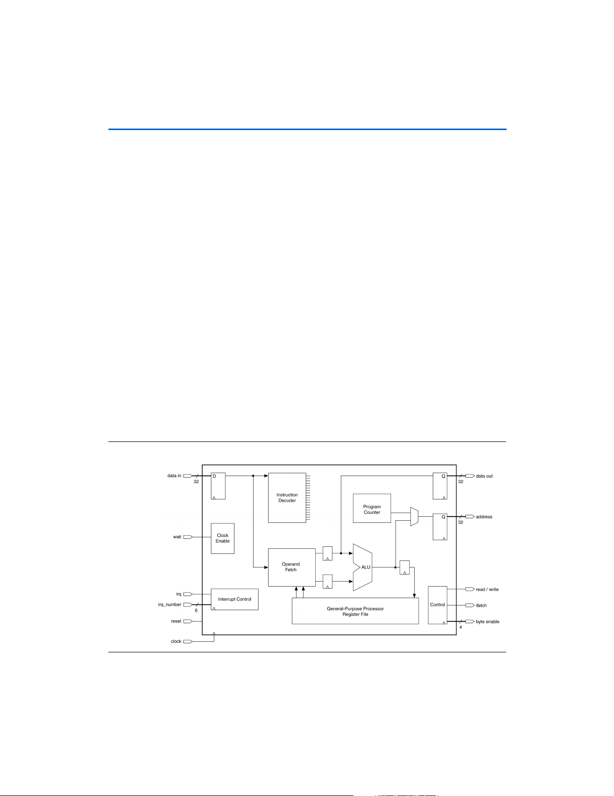
Pipeline Implementation
Figure 4. Nios CPU Block Diagram
22 Altera Corporation
This topics in this section include a description of the following:
■ Nios CPU pipeline
■ Exposed pipeline branch delay and direct CWP manipulation
Page 35
GettingOverview
Pipeline Operation
The Nios CPU is pipelined RISC architecture. The pipeline
implementation is hidden from software except for branch delay slots and
when CWP is modified by a WRCTL direct write. The pipeline stages
include:
■ Instruction Fetch—the Nios CPU issues an address, and the memory
subsystem then returns the instruction stored at the issued address.
■ Instruction Decode / Operand Fetch—the fetched instruction is
decoded. If there are register operands, they are read from the
register file. A dedicated branch-target adder computes the
destination address for BR and BSR instructions.
■ Execute—the operands and control bits are presented to the ALU.
The ALU then computes a result.
■ Write-back—the ALU result is written back into the destination
register when applicable.
Branch Delay Slots
A branch delay slot is defined as the instruction immediately after a BR,
BSR, CALL, or JMP instruction. A branch delay slot is executed after the
branch instruction but before the branch-target instruction. Table 15
illustrates a branch delay-slot for a BR instruction.
Table 15. BR Branch Delay Slot Example
…
(a) ADD %g2, %g3
(b) BR Target
(c) ADD %g4, %g5
(d) ADD %g6, %g7
…
Target:
(e) ADD %g8, %g9
Branch D elay Slot
1
Overview
Altera Corporation 23
Page 36

Overview
After branch instruction (b) is taken, instruction (c) is executed before
control is transferred to the branch target (e). The execution sequence of
the above code fragment would be (a), (b), (c), and (e). Instruction (c) is
instruction (b)’s branch delay slot. Instruction (d) is not executed. Most
instructions can be used as a branch delay slot except for those listed
below:
■ BR
■ BSR
■ CALL
■ IF1
■ IF0
■ IFRnz
■ IFRz
■ IFS
■ JMP
■ LRET
■ PFX
■ RET
■ SKP1
■ SKP0
■ SKPRnz
■ SKPRz
■ SKPS
■ TRET
■ TRAP
Direct CWP Manipulation
Every WRCTL instruction that modifies the STATUS register (%ctl0) must
be followed by a NOP instruction.
24 Altera Corporation
Page 37

GettingOverview
Table 16. Notation Details
Notation Meaning Notation Meaning
X ← Y X is written with Y X >> n The value X after being right-shifted n bit
positions
∅←e Expression e is evaluated, and the result
is discarded
RA One of the 32 visible registers, selected
by the 5-bit a-field of the instruction word
RB One of the 32 visible registers, selected
by the 5-bit b-field of the instruction word
RP One of the 4 pointer-enabled (P-type)
registers, selected by the 2-bit p-field of
the instruction word
IMMn An n-bit immediate value, embedded in
the instruction word
K The 11-bit value held in the K register. (K
can only be set by a PFX instruction)
0xnn.mm Hexadecimal notation (decimal points not
significant, added for clarity)
X : Y Bitwise-concatenation operator.
e.g.: (0x12 : 0x34) = 0x1234
{e1, e2} Conditional expression. Evaluates to e2
if previous instruction was PFX,
e1 otherwise
σ(X) X after being sign-extended into a full
register-sized signed integer
th
X[n] The n
X[n..m] Consecutive bits n through m of X align32(X) X & 0xFF.FF.FF.FC, which is the integer
C The C (carry) flag in the STATUS register
CTLk One of the 2047 control registers selected
bit of X (n = 0 means LSB) align16(X) X & 0xFF.FE, which is the integer value X
by K
X << n The value X after being left-shifted n bit
positions
bn
X The nth byte (8-bit field) within the
full-width value X.
b1
X = X[15..8], b2X = X[23..16], and
b3
X = X[31..24]
hn
X The nth half-word (16-bit field) within the
full-width value X.
h1
X = X[31..16]
X & Y Bitwise logical AND
X | Y Bitwise logical OR
X ⊕ Y Bitwise logical exclusive OR
~X Bitwise logical NOT (one’s complement)
|X| The absolute value of X
(i.e. –X if (X < 0), X otherwise).
Mem32[X] The aligned 32-bit word value stored in
external memory, starting at byte address
X
Mem16[X] The aligned 16-bit half-word value stored
in external memory, starting at byteaddress X
forced into half-word alignment via
truncation
value X forced into full-word alignment via
truncation
b0
X = X[7..0],
h0
X = X[15..0],
1
Overview
Altera Corporation 25
Page 38

Overview
Instruction Format (Sheet 1 of 2)
RR 15 14 13 12 11 10 9 8 7 6 5 4 3 2 1 0
op6 B A
Ri51514131211109876543210
op6 IMM5 A
Ri41514131211109876543210
op6 0 IMM4 A
RPi5 15 14 13 12 11 10 9 8 7 6 5 4 3 2 1 0
op4 P B A
Ri61514131211109876543210
op5 IMM6 A
Ri81514131211109876543210
op3 IMM8 A
i9 15 14 13 12 11 10 9 8 7 6 5 4 3 2 1 0
op6 IMM9 0
i101514131211109876543210
op6 IMM10
i111514131211109876543210
op5 IMM11
Ri1u 15 14 13 12 11 10 9 8 7 6 5 4 3 2 1 0
op6 op3u
IMM1u
0
A
Ri2u 15 14 13 12 11 10 9 8 7 6 5 4 3 2 1 0
op6 op3u IMM2u A
26 Altera Corporation
Page 39

GettingOverview
Instruction Format (Sheet 2 of 2)
i8v1514131211109876543210
op6 op2v IMM8v
i6v1514131211109876543210
op6 op2v 0 0 IMM6v
Rw 15 14 13 12 11 10 9 8 7 6 5 4 3 2 1 0
op6 op5w A
i4w1514131211109876543210
op6 op5w 0 IMM4w
w 1514131211109876543210
op6 op5w 0 0 0 0 0
1
Overview
Altera Corporation 27
Page 40

Overview
Table 17. 32-bit Major Opcode Table (Sheet 1 of 3)
Opcode Mnemonic Format Summary
000000 ADD RR RA ← RA + RB
Flags affected: N, V, C, Z
000001 ADDI Ri5 RA ← RA + (0×00.00 : K : IMM5)
Flags affected: N, V, C, Z
000010 SUB RR RA ← RA – RB
Flags affected: N, V, C, Z
000011 SUBI Ri5 RA ← RA – (0×00.00 : K : IMM5)
Flags affected: N, V, C, Z
000100 CMP RR ∅ ← RA – RB
Flags affected: N, V, C, Z
000101 CMPI Ri5 ∅ ← RA – (0×00.00 : K : IMM5)
Flags affected: N, V, C, Z
000110 LSL RR RA ← (RA << RB [4..0]),
Zero-fill from right
000111 LSLI Ri5 RA ← (RA << IMM5),
Zero-fill from right
001000 LSR RR RA ← (RA >> RB [4..0]),
Zero-fill from left
001001 LSRI Ri5 RA ← (R >> IMM5),
Zero-fill form left
001010 ASR RR RA ← (RA >> RB [4..0]),
Fill from left with RA[31]
001011 ASRI Ri5 RA ← (RA >> IMM5),
Fill from left with RA[31]
001100 MOV RR RA ← RB
001101 MOVI Ri5 RA ← (0×00.00 : K : IMM5)
001110 AND RR
Ri5
001111 ANDN RR,
Ri5
010000 OR RR,
Ri5
010001 XOR RR,
Ri5
010010 BGEN Ri5 RA ← 2
010011 EXT8d RR RA ← (0×00.00.00 : bnRA) where n = RB[1..0]
010100 SKP0 Ri5 Skip next instruction if: (RA [IMM5] == 0)
010101 SKP1 Ri5 Skip next instruction if: (RA [IMM5] == 1)
010110 LD RR RA ← Mem32 [align32( RB + (σ(K) × 4))]
RA ← RA & {RB, (0×00.00 : K : IMM5)}
Flags affected: N, Z
RA ← RA & ~({RB, (0×00.00 : K : IMM5)})
Flags affected: N, Z
RA ← RA | {RB, (0×00.00 : K : IMM5)}
Flags affected: N, Z
RA ← RA ⊕ {RB, (0×00.00 : K : IMM5)}
Flags affected: N, Z
IMM5
28 Altera Corporation
Page 41

GettingOverview
Table 17. 32-bit Major Opcode Table (Sheet 2 of 3)
Opcode Mnemonic Format Summary
010111 ST RR Mem32 [align32( RB + (σ(K) × 4))] ← RA
011000 STS8s i10
011001 STS16s i9
011010 EXT16d RR RA ← (0×00.00 :
011011 MOVHI Ri5
011100 USR0 RR Reserved for future use
011101000 EXT8s Ri1u RA ← (0×00.00.00 :
011101001 EXT16s Ri1u RA ← (0×00.00 :
011101010
011101011
011101100 ST8s Ri1u
011101101 ST16s Ri1u
01111000 SAVE i8v CWP ← CWP – 1; %sp ← %fp – (IMM8v × 4)
0111100100 TRAP i6v ISTATUS ← STATUS; IE ← 0; CWP ← CWP – 1;
01111100000 NOT Rw RA ← ~RA
01111100001 NEG Rw RA ← 0 – RA
01111100010 ABS Rw RA ← |RA|
01111100011 SEXT8 Rw RA ← σ(
01111100100 SEXT16 Rw RA ← σ(
01111100101 RLC Rw C ← msb (RA); RA ← (RA << 1) : C
01111100110 RRC Rw C ← RA[0]; RA ← C : (RA >> 1)
01111100111
01111101000 SWAP Rw RA ←
01111101001 USR1 Rw Reserved for future use
01111101010 USR2 Rw Reserved for future use
01111101011 USR3 Rw Reserved for future use
01111101100 USR4 Rw Reserved for future use
01111101101 RESTORE w CWP ← CWP + 1; if (old-CWP == HI_LIMIT) {TRAP #2}
01111101110 TRET Rw PC ← (RA × 2); STATUS ← ISTATUS
bn
Mem32 [align32(%sp + IMM10)] ← bn%r0
where n = IMM10[1..0]
hn
Mem32 [align32( %sp + IMM9 × 2)] ←
hn
%r0
where n = IMM9[0]
hn
h1
RA ← (K : IMM5), h0RA unaffected
bn
Mem32 [align32(RA + (σ(K) × 4))] ← bn%r0
RA) where n = RB[1]
bn
RA) where n = IMM2u
hn
RA) where n = IMM1u
where n = IMM2u
hn
Mem32 [align32(RA + (σ(K) × 4))] ← hn%r0
where n = IMM1u
If (old-CWP == LO_LIMIT) {TRAP #1}
IPRI ← IMM6v; %r15 ← ((PC + 2) >> 1) ;
PC ← Mem32 [VECBASE + (IMM6v × 4)] × 2
b0
RA)
h0
RA)
Flag affected: C
Flag affected: C
h0
RA : h1RA
1
Overview
Altera Corporation 29
Page 42

Overview
Table 17. 32-bit Major Opcode Table (Sheet 3 of 3)
Opcode Mnemonic Format Summary
01111101111
01111110000 ST8d Rw
01111110001 ST16d Rw
01111110010 FILL8 Rw %r0 ← (
01111110011 FILL16 Rw %r0 ← (
01111110100 MSTEP Rw if (%r0[31] == 1) then %r0 ← (%r0 << 1) + RA else %r0
01111110101 MUL Rw %r0 ← (%r0 & 0x0000.ffff) × (RA & 0x0000.ffff)
01111110110 SKPRz Rw Skip next instruction if:(RA ==0)
01111110111 SKPS i4w Skip next instruction if condition encoded by IMM4w is true
01111111000 WRCTL Rw CTLk ← RA
01111111001 RDCTL Rw RA ← CTLk
01111111010 SKPRnz Rw Skip next instruction if: (RA ! = 0)
01111111011
01111111100
01111111101
01111111110 JMP Rw PC ← (RA × 2)
01111111111 CALL Rw R15 ← ((PC + 4) >> 1); PC ← (RA × 2)
100000 BR i11 PC ← PC + ((σ(IMM11) + 1) × 2)
100001
100010 BSR i11 PC ← PC + ((σ(IMM11) + 1) × 2);
10011 PFX i11 K ← IMM11 (K set to zero after next instruction)
1010 STP RPi5 Mem32[align32(RP + (σ(K : IMM5) × 4))] ← RA
1011 LDP RPi5 RA ← Mem32 [align32(RP + (σ(K : IMM5) × 4))]
110 STS Ri8 Mem32[align32(%sp + (IMM8 × 4) )] ← RA
111 LDS Ri8 RA ← Mem32 [align32(%sp + (IMM8 × 4))]
bn
Mem32 [align32(RA +(σ(K) × 4))] ← bn%r0
where n = RA[1..0]
hn
Mem32 [align32(RA + (σ(K) × 4))] ← hn%r0
where n = RA[1]
b0
RA : b0RA : b0RA : b0RA)
h0
RA : h0RA)
← (%r0 << 1)
%r15 ← ((PC + 4) >> 1)
30 Altera Corporation
Page 43

GettingOverview
The following pseudo-instructions are generated by nios-elf-gcc (GNU
compiler) and understood by nios-elf-as (GNU assembler).
Table 18. GNU Compiler/Assembler Pseudo-instructions
Psuedo-Instruction Equivalent Instruction Notes
LRET JMP %o7 LRET has no operands
RET JMP %i7 RET has no operands
NOP MOV %g0,%g0 NOP has no operands
IF0 %rA,IMM5 SKP1 %rA,IMM5
IF1 %rA,IMM5 SKP0 %rA,IMM5
IFRz %rA SKPRnz %rA
IFRnz %rA SKPRz %rA
IFS cc_c SKPS cc_nc
IFS cc_nc SKPS cc_c
IFS cc_z SKPS cc_nz
IFS cc_nz SKPS cc_z
IFS cc_mi SKPS cc_pl
IFS cc_pl SKPS cc_mi
IFS ccge SKPS cc_lt
IFS cc_lt SKPS cc_ge
IFS cc_le SKPS cc_gt
IFS cc_gt SKPS cc_le
IFS cc_v SKPS cc_nv
IFS cc_nv SKPS cc_v
IFS cc_ls SKPS cc_hi
IFS cc_hi SKPS cc_ls
1
Overview
The following operators are understood by nios-elf-as. These operators
may be used with constants and symbolic addresses, and can be correctly
resolved either by the assembler or the linker.
Operator Description Operation
%lo(x) Extract low 5 bits of x. x & 0×0000001f
%hi(x) Extract bits 5..15 of x.(x >> 5) & 0×000007ff
%xlo(x) Extract bits 16..20 of x.(x >> 1 (x >> 16) & 0×0000001f
%xhi(x) Extract bits 21..31 of x.(x >> 21) & 0×000007ff
x@h Half-word address of x. x >> 1
Altera Corporation 31
Page 44

Notes:
32 Altera Corporation
Page 45

32-Bit Instruction Set
This section provides a detailed description of the 32-bit Nios CPU
instructions. The descriptions are arranged in alphabetical order
according to instruction mnemonic. Each instruction page includes the
following information:
■ Instruction mnemonic and description
■ Description of operation
■ Assembler syntax
■ Syntax example
■ Operation description
■ Prefix actions
■ Condition codes
■ Instruction format
■ Instruction fields
1 The ∆ symbol found in the condition code flags table indicates
flags are changed by the instruction.
2
32-Bit Instruction
Set
Altera Corporation 33
Page 46

32-Bit Instruction Set
ABS
Absolute Value
Operation: RA ← |RA|
Assembler Syntax: ABS %rA
Example: ABS %r6
Description: Calculate the absolute value of RA; store the result in RA.
Condition Codes: Flags: Unaffected
NVZC
−−−−
Instruction Format: Rw
Instruction Fields: A = Register index of operand RA
1514131211109876543210
01111100010 A
34 Altera Corporation
Page 47

3232323232-Bit Instruction Set
ADD
Add Without Carry
Operation: RA ← RA + RB
Assembler Syntax: ADD %rA,%rB
Example: ADD %L3,%g0 ; ADD %g0 to %L3
Description: Adds the contents of register A to register B and stores the result in register A.
Condition Codes: Flags:
NVZC
∆∆∆∆
N: Result bit 31
V: Signed-arithmetic overflow
Z: Set if result is zero; cleared otherwise
C: Carry-out of addition
Instruction Format: RR
Instruction Fields: A = Register index of RA operand
B = Register index of RB operand
1514131211109876543210
000000 B A
2
32-Bit Instruction
Set
Altera Corporation 35
Page 48

32-Bit Instruction Set
ADDI
Add Immediate
Operation: RA ← RA + (0x00.00 : K : IMM5)
Assembler Syntax: ADDI %rA,IMM5
Example: Not preceded by PFX:
ADDI %L5,6 ; add 6 to %L5
Preceded by PFX:
PFX %hi(1000)
ADDI %g3,%lo(1000) ; ADD 1000 to % g3
Description: Not preceded by PFX:
Adds 5-bit immediate value to register A, stores result in register A. IMM5 is in the
range [0..31].
Preceded by PFX:
The immediate operand is extended from 5 to 16 bits by concatenating the
contents of the K-register (11 bits) with IMM5 (5 bits). The 16-bit immediate value
(K : IMM5) is zero-extended to 32 bits and added to register A.
Condition Codes: Flags:
NVZC
∆∆∆∆
N: Result bit 31
V: Signed-arithmetic overflow
Z: Set if result is zero; cleared otherwise
C: Carry-out of addition
Instruction Format: Ri5
Instruction Fields: A = Register index of RA operand
IMM5 = 5-bit immediate value
1514131211109876543210
000001 IMM5 A
36 Altera Corporation
Page 49

Operation: Not preceded by PFX:
RA ← RA & RB
Preceded by PFX:
RA
← RA & (0x00.00 : K : IMM5)
Assembler Syntax: Not preceded by PFX:
AND %rA,%rB
Preceded by PFX:
PFX %hi(const)
AND %rA,%lo(const)
Example: Not preceded by PFX:
AND %g0,%g1 ; %g0 gets %g1 & %g0
Preceded by PFX:
PFX %hi(16383)
AND %g0,%lo(16383) ; AND %g0 with 16383
Description: Not preceded by PFX:
Logically-AND the individual bits in RA with the corresponding bits in RB; store
the result in RA.
Preceded by PFX:
When prefixed, the RB operand is replaced by an immediate constant formed by
concatenating the contents of the K-register (11 bits) with IMM5 (5 bits). This
16-bit value (zero-extended to 32 bits) is bitwise-ANDed with RA, and the result
is written back into RA.
Condition Codes: Flags:
NVZC
∆ – ∆ –
N: Result bit 31
Z: Set if result is zero, cleared otherwise
Instruction Format: RR, Ri5
Instruction Fields: A = Register index of RA operand
B = Register index of RB operand
IMM5 = 5-bit immediate value
3232323232-Bit Instruction Set
AND
Bitwise Logical AND
2
32-Bit Instruction
Set
Not preceded by PFX (RR)
1514131211109876543210
001110 B A
Preceded by PFX (Ri5)
1514131211109876543210
001110 IMM5 A
Altera Corporation 37
Page 50

32-Bit Instruction Set
ANDN
Bitwise Logical AND NOT
Operation: Not preceded by PFX:
RA ← RA & ~RB
Preceded by PFX:
RA
← RA & ~(0x00.00 : K : IMM5)
Assembler Syntax: Not preceded by PFX:
ANDN %rA,%rB
Preceded by PFX:
PFX %hi(const)
ANDN %rA,%lo(const)
Example: Not preceded by PFX:
ANDN %g0,%g1 ; %g0 gets %g0 & ~%g1
Preceded by PFX:
PFX %hi(16384)
ANDN %g0,%lo(16384) ; clear bit 14 of %g0
Description: Not preceded by PFX:
Logically-AND the individual bits in RA with the corresponding bits in the one’s-
complement of RB; store the result in RA.
Preceded by PFX:
When prefixed, the RB operand is replaced by an immediate constant formed by
concatenating the contents of the K-register (11 bits) with IMM5 (5 bits). This
16-bit value is zero-extended to 32 bits, then bitwise-inverted and bitwise-ANDed
with RA. The result is written back into RA.
Condition Codes: Flags:
NVZC
∆ – ∆ –
N: Result bit 31
Z: Set if result is zero, cleared otherwise
Instruction Format: RR, Ri5
Instruction Fields: A = Register index of operand RA
B = Register index of operand RB
IMM5 = 5-bit immediate value
Not preceded by PFX (RR)
1514131211109876543210
001111 B A
Preceded by PFX (Ri5)
1514131211109876543210
001111 IMM5 A
38 Altera Corporation
Page 51

3232323232-Bit Instruction Set
ASR
Arithmetic Shift Right
Operation: RA ← (RA >> RB[4..0]), fill from left with RA[31]
Assembler Syntax: ASR %rA,%rB
Example: ASR %L3,%g0 ; shift %L3 right by %g0 bits
Description: Arithmetically shift right the value in RA by the value of RB; store the result in RA.
Bits 31..5 of RB are ignored. If the value in RB[4..0] is 31, RA will be zero or
negative one depending on the original sign of RA.
Condition Codes: Flags: Unaffected
NVZC
−−−−
Instruction Format: RR
Instruction Fields: A = Register index of RA operand
B = Register index of RB operand
2
32-Bit Instruction
Set
1514131211109876543210
001010 B A
Altera Corporation 39
Page 52

32-Bit Instruction Set
ASRI
Arithmetic Shift Right Immediate
Operation: RA ← (RA >> IMM5), fill from left with RA[31]
Assembler Syntax: ASRI %rA,IMM5
Example: ASRI %i5,6 ; shift %i5 right 6 bits
Description: Arithmetically shift right the contents of RA by IMM5 bits. If IMM5 is 31, RA will be
zero or negative one depending on the original sign of RA.
Condition Codes: Flags: Unaffected
NVZC
−−−−
Instruction Format: Ri5
Instruction Fields: A = Register index of RA operand
IMM5 = 5-bit immediate value
1514131211109876543210
001011 IMM5 A
40 Altera Corporation
Page 53

3232323232-Bit Instruction Set
BGEN
Bit Generate
Operation: RA ← 2
Assembler Syntax: BGEN %rA,IMM5
Example: BGEN %g7,6 ; set %g7 to 64
Description: Sets RA to an integer power-of-two with the exponent given by IMM5. This is
Condition Codes: Flags: Unaffected
Instruction Format: Ri5
Instruction Fields: A = Register index of RA operand
1514131211109876543210
010010 IMM5 A
IMM5
equivalent to setting a single bit in RA, and clearing the rest.
NVZC
−−−−
IMM5 = 5-bit immediate value
2
32-Bit Instruction
Set
Altera Corporation 41
Page 54

32-Bit Instruction Set
BR
Branch
Operation: PC ← PC + ((σ(IMM11) + 1) << 1)
Assembler Syntax: BR addr
Example: BR MainLoop
NOP ; (delay slot)
Description: The offset given by IMM11 is interpreted as a signed number of half-words
(instructions) relative to the instruction immediately following BR. Program control
is transferred to instruction at this offset.
Condition Codes: Flags: Unaffected
NVZC
−−−−
Delay Slot Behavior: The instruction immediately following BR (BR’s delay slot) is executed after BR,
but before the destination instruction. There are restrictions on which instructions
may be used as a delay slot. (Refer to “Branch Delay Slots” on page 23)
Instruction Format: i11
Instruction Fields: IMM11 = 11-bit immediate value
1514131211109876543210
10000 IMM11
42 Altera Corporation
Page 55

3232323232-Bit Instruction Set
BSR
Branch To Subroutine
Operation: %o7 ← ((PC + 4) >> 1)
PC ← PC + ((σ(IMM11)+1)<<1)
Assembler Syntax: BSR addr
Example: BSR SendCharacter
NOP ; (delay slot)
Description: The offset given by IMM11 is interpreted as a signed number of half-words
(instructions) relative to the instruction immediately following BR. Program control
is transferred to instruction at this offset. The return-address is the address of the
BSR instruction plus four, which is the address of the second subsequent
instruction. The return-address is shifted right one bit and stored in %o7. The
right-shifted value stored in %o7 is a destination suitable for direct use by JMP
without modification.
Condition Codes: Flags: Unaffected
NVZC
−−−−
Delay Slot Behavior: The instruction immediately following BSR (BSR’s delay slot) is executed after
BSR, but before the destination instruction. There are restrictions on which
instructions may be used as a delay slot. (Refer to “Branch Delay Slots” on
page 23)
Instruction Format: i11
Instruction Fields: IMM11 = 11-bit immediate value
2
32-Bit Instruction
Set
1514131211109876543210
10001 IMM11
Altera Corporation 43
Page 56

32-Bit Instruction Set
CALL
Call Subroutine
Operation: %o7 ← ((PC + 4) >> 1)
PC ← (RA << 1)
Assembler Syntax: CALL %rA
Example: CALL %g0
NOP ; (delay slot)
Description: The value of RA is shifted left by one and transferred into PC. RA contains the
address of the called subroutine right-shifted by one bit. The return-address is the
address of the second subsequent instruction. Return-address is shifted right one
bit and stored in %o7. The right-shifted value stored in %o7 is a destination
suitable for direct use by JMP without modification.
Condition Codes: Flags: Unaffected
NVZC
−−−−
Delay Slot Behavior: The instruction immediately following CALL (CALL’s delay slot) is executed after
CALL, but before the destination instruction. There are restrictions on which
instructions may be used as a delay slot. (Refer to “Branch Delay Slots” on
page 23)
Instruction Format: Rw
Instruction Fields: A = Register index of operand RA
1514131211109876543210
011111 11111 A
44 Altera Corporation
Page 57

3232323232-Bit Instruction Set
CMP
Compare
Operation: ∅←RA − RB
Assembler Syntax: CMP %rA,%rB
Example: CMP %g0,%g1 ; set flags by %g0 - %g1
Description: Subtract the contents of RB from RA, and discard the result. Set the condition
codes according to the subtraction. Neither RA nor RB are altered.
Condition Codes: Flags:
NVZC
∆∆∆∆
N: Result bit 31
V: Signed-arithmetic overflow
Z: Set if result is zero; cleared otherwise
C: Set if there was a borrow from the subtraction; cleared otherwise
Instruction Format: RR
Instruction Fields: A = Register index of RA operand
B = Register index of RB operand
1514131211109876543210
000100 B A
2
32-Bit Instruction
Set
Altera Corporation 45
Page 58

32-Bit Instruction Set
CMPI
Compare Immediate
Operation: ∅←RA–(0x00.00:K:IMM5)
Assembler Syntax: CMPI & %rA,IMM5
Example: Not preceded by PFX:
CMPI %i3,24 ; compare %i3 to 24
Preceded by PFX:
PFX %hi(1000)
CMPI %i4,%lo(1000)
Description: Not preceded by PFX:
Subtract a 5-bit immediate value given by IMM5 from RA, and discard the result.
Set the condition codes according to the subtraction. RA is not altered.
Preceded by PFX:
The Immediate operand is extended from 5 to 16 bits by concatenating the
contents of the K-register (11 bits) with IMM5 (5 bits). The 16-bit immediate value
(K : IMM5) is zero-extended to 32 bits and subtracted from RA. Condition codes
are set and the result is discarded. RA is not altered.
Condition Codes: Flags:
NVZC
∆∆∆∆
N: Result bit 31
V: Signed-arithmetic overflow
Z: Set if result is zero; cleared otherwise
C: Set if there was a borrow from the subtraction; cleared otherwise
Instruction Format: Ri5
Instruction Fields: A = Register index of RA operand
IMM5 = 5-bit immediate value
1514131211109876543210
000101 IMM5 A
46 Altera Corporation
Page 59

3232323232-Bit Instruction Set
EXT16d
Half-Word Extract (Dynamic)
hn
Operation:
Assembler Syntax: EXT16d %rA,%rB
Example: LD %i3,[%i4] ; get 32 bits fro m [%i4 & 0xFF.FF.FF.FC]
Description: Extracts one of the two half-words in RA. The half-word to-be-extracted is chosen
Condition Codes: Flags: Unaffected
RA ← (0x00.00 :
EXT16d %i3,%i4 ; extract short int at %i4
by bit 1 of RB. The selected half-word is written into bits 15..0 of RA, and the
more-significant bits 31..16 are set to zero.
NVZC
−−−−
RA) where n = RB[1]
2
32-Bit Instruction
Set
Instruction Format: RR
Instruction Fields: A = Register index of operand RA
B = Register index of operand RB
1514131211109876543210
011010 B A
Altera Corporation 47
Page 60

32-Bit Instruction Set
EXT16s
Half-Word Extract (Static)
hn
Operation:
Assembler Syntax: EXT16s %rA,IMM1
Example: EXT16s %L3,1 ; %L3 gets upper short int of itself
Description: Extracts one of the two half-words in RA. The half-word to-be-extracted is chosen
Condition Codes: Flags: Unaffected
RA ← (0x00.00 :
by the one-bit immediate value IMM1. The selected half-word is written into bits
15..0 of RA, and the more significant bits 31..16 are set to zero.
NVZC
−−−−
RA) where n = IMM1
Instruction Format: Ri1u
Instruction Fields: A = Register index of operand RA
IMM1 = 1-bit immediate value
1514131211109876 543210
011101001IMM10 A
48 Altera Corporation
Page 61

3232323232-Bit Instruction Set
EXT8d
Byte-Extract (Dynamic)
bn
Operation:
Assembler Syntax: EXT8d %rA,%rB
Example: LD %g4,[%i0] ; get 32 bits fro m [%i0 & 0xFF.FF.FF.FC]
Description: Extracts one of the four bytes in RA. The byte to-be-extracted is chosen by bits
RA ← (0x00.00.00 :
EXT8d %g4,%i0 ; extract the particular byte at %i0
1..0 of RB (byte 3 being the most-significant byte of RA). The selected byte is
written into bits 7..0 of RA, and the more-significant bits 31..8 are set to zero.
RA) where n = RB[1..0]
2
32-Bit Instruction
Set
Condition Codes: Flags: Unaffected
NVZC
−−−−
Instruction Format: RR
Instruction Fields: A = Register index of operand RA
B = Register index of operand RB
1514131211109876543210
010011 B A
Altera Corporation 49
Page 62
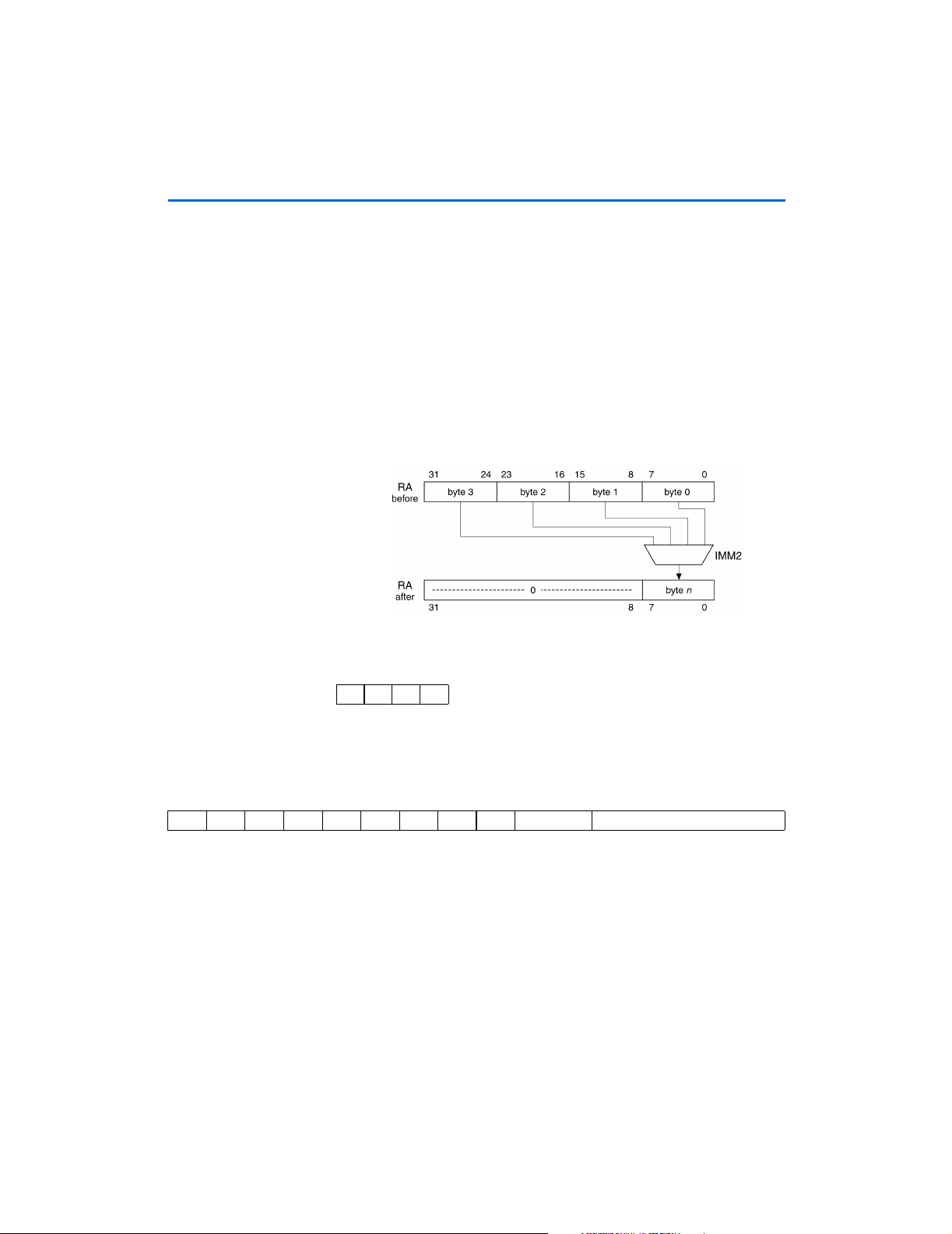
32-Bit Instruction Set
EXT8s
Byte-Extract (Static)
bn
Operation:
Assembler Syntax: EXT8s %rA,IMM2
Example: EXT8s %g6,3 ; %g6 gets the 3rd byte of its elf
Description: Extracts one of the four bytes in RA. The byte to-be-extracted is chosen by the
RA ← (0x00.00.00 :
immediate value IMM2 (byte 3 being the most-significant byte of RA). The
selected byte is written into bits 7..0 of RA, and the more-significant bits 31..8 are
set to zero.
RA) where n = IMM2
Condition Codes: Flags: Unaffected
NVZC
−−−−
Instruction Format: Ri2u
Instruction Fields: A = Register index of operand RA
IMM2 = 2-bit immediate value
1514131211109876543210
0 11101 000 IMM2 A
50 Altera Corporation
Page 63

3232323232-Bit Instruction Set
FILL16
Half-Word Fill
h0
RA :h0RA)
Operation:
Assembler Syntax: FILL16 %r0,%rA
Example: FILL16 %r0,%i3 ; %r0 gets 2 co pies of %i3[0..15]
Description: The least significant half-word of RA is copied into both half-word positions
Condition Codes: Flags: Unaffected
R0 ← (
; first operand mus t be %r0
in %r0. %r0 is the only allowed destination operand for FILL instructions.
NVZC
−−−−
2
32-Bit Instruction
Set
Instruction Format: Rw
Instruction Fields: A = Register index of operand RA
1514131211109876543210
011111 10011 A
Altera Corporation 51
Page 64
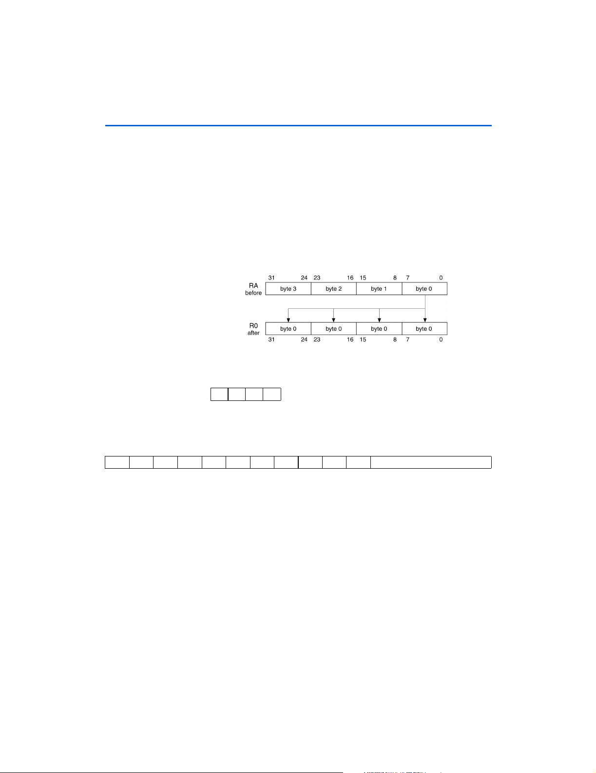
32-Bit Instruction Set
FILL8
Byte-Fill
b0
RA :b0RA :b0RA :b0RA)
Operation:
Assembler Syntax: FILL8 %r0,%rA
Example: FILL8 %r0,%o3 ; %r0 gets 4 cop ies of %o3[0..7]
Description: The least-significant byte of RA is copied into all four byte-positions in %r0. %r0
Condition Codes: Flags: Unaffected
R0 ← (
; first operand must be %r0
is the only allowed destination operand for FILL instructions.
NVZC
−−−−
Instruction Format: Rw
Instruction Fields A = Register index of operand RA
1514131211109876543210
011111 10010 A
52 Altera Corporation
Page 65

3232323232-Bit Instruction Set
IF0
Equivalent to SKP1 Instruction
Operation:
Assembler Syntax: IF0 %rA,IMM5
Example: IF0 %o3,21 ; do if 21st bit of %o3 is zero
Description: Skip next instruction if the single bit RA[IMM5] is 1. If the next instruction is PFX,
Condition Codes: Flags: Unaffected
Instruction Format: Ri5
Instruction Fields: A = Register index of operand RA
1514131211109876543210
010101 IMM5 A
if (RA[IMM5] = = 1)
then begin
if (Mem16[PC + 2] is PFX)
then PC ← PC + 6
else PC ← PC + 4
end
ADDI %g0,1 ; increment if 21st bit clear
then both PFX and the instruction following PFX are skipped together.
NVZC
−−−−
IMM5 = 5-bit immediate value
2
32-Bit Instruction
Set
Altera Corporation 53
Page 66

32-Bit Instruction Set
IF1
Equivalent to SKP0 Instruction
Operation:
Assembler Syntax: IF1 %rA,IMM5
Example: ADDI %g0,1 ; include if bit 7 was set
Description: Skip next instruction if the single bit RA[IMM5] is 0. If the next instruction is PFX,
Condition Codes: Flags: Unaffected
Instruction Format: Ri5
Instruction Fields: A = Register index of operand RA
1514131211109876543210
010100 IMM5 A
if (RA[IMM5] = = 0)
then begin
if (Mem16[PC + 2] is PFX)
then PC ← PC + 6
else PC ← PC + 4
end
then both PFX and the instruction following PFX are skipped together.
NVZC
−−−−
IMM5 = 5-bit immediate value
54 Altera Corporation
Page 67
3232323232-Bit Instruction Set
IFRnz
Equivalent to SKPRz Instruction
Operation:
Assembler Syntax: IFRnz %rA
Example: IFRnz %o3
Description: Skip next instruction if RA is equal to zero. If the next instruction is PFX, then both
Condition Codes: Flags: Unaffected
Instruction Format: Rw
Instruction Fields: A = Register index of operand RA
1514131211109876543210
011111 10110 A
if (RA==0)
then begin
if (Mem16[PC + 2] is PFX)
then PC ← PC + 6
else PC ← PC + 4
end
BSR SendIt ; only call if %o3 is n ot 0
NOP ; (delay slot) executed in eit her case
PFX and the instruction following PFX are skipped together.
NVZC
−−−−
2
32-Bit Instruction
Set
Altera Corporation 55
Page 68

32-Bit Instruction Set
IFRz
Equivalent to SKPRnz Instruction
Operation:
Assembler Syntax: IFRz %rA
Example: IFRz %g3
Description: Skip next instruction if RA is not zero. If the next instruction is PFX, then both PFX
Condition Codes: Flags: Unaffected
Instruction Format: Rw
Instruction Fields: A = Register index of operand RA
1514131211109876543210
011111 11010 A
if (RA ! = 0)
then begin
if (Mem16[PC + 2] is PFX)
then PC ← PC + 6
else PC ← PC + 4
end
BSR SendIt ; only call if %g3 is z ero
NOP ; (delay slot) executed in eit her case
and the instruction following PFX are skipped together.
NVZC
−−−−
56 Altera Corporation
Page 69

3232323232-Bit Instruction Set
IFS
Conditionally Execute Next Instruction
Operation:
Assembler Syntax: IFS cc_IMM4
Example: IFS cc_ne
Description: Execute next instruction if specified condition is true, skip if condition is false. If
Condition Codes: Settings:
1 These condition
codes have
different numeric
values for IFS and
SKPS instructions.
Instruction Format: i4w
Instruction Fields: IMM4 = 4-bit immediate value
if (condition IMM4 is false)
then begin
if (Mem16[PC + 2] is PFX)
then PC ← PC + 6
else PC ← PC + 4
end
BSR SendIt ; only call if Z flag s et
NOP ; (delay slot) executed in eit her case
the next instruction is PFX, then both PFX and the instruction following PFX are
skipped together.
cc_nc 0x0 (not C)
cc_c 0x1 (C)
cc_nz 0x2 (not Z)
cc_z 0x3 (Z)
cc_pl 0x4 (not N)
cc_mi 0x5 (N)
cc_lt 0x6 (N xor V)
cc_ge 0x7 (not (N xor V))
cc_gt 0x8 (Not (Z or (N xor V)))
cc_le 0x9 (Z or (N xorV))
cc_nv 0xa (not V)
cc_v 0xb (V)
cc_hi 0xc (not (C or Z))
cc_la 0xd (C or Z)
Additional alias flags allowed:
cc_cs = cc_c
cc_eq = cc_z
Codes mean execute if, e.g., ifs cc_eq means execute if equal
cc_n = cc_mi
cc_vs = cc_v
cc_cc = cc_nc
cc_ne = cc_nz
cc_vc = cc_nv
cc_p = cc_pl
2
32-Bit Instruction
Set
1514131211109876543210
011111101110 IMM4
Altera Corporation 57
Page 70

32-Bit Instruction Set
JMP
Computed Jump
Operation:
Assembler Syntax: JMP %rA
Example: JMP %o7 ; return
Description: Jump to the target-address given by (RA << 1). Note that the target address will
Condition Codes: Flags: Unaffected
Delay Slot Behavior: The instruction immediately following JMP (JMP’s delay slot) is executed after
Instruction Format: Rw
Instruction Fields: A = Register index of operand RA
1514131211109876543210
011111 11110 A
PC ← (RA << 1)
NOP ; (delay slot)
always be half-word aligned for any value of RA.
NVZC
−−−−
JMP, but before the destination instruction. There are restrictions on which
instructions may be used as a delay slot. (Refer to “Branch Delay Slots” on
page 23)
58 Altera Corporation
Page 71

Operation: Not preceded by PFX:
RA ← Mem32[align32(RB)]
Preceded by PFX:
RA ← Mem32[align32(RB + σ(K) × 4))]
Assembler Syntax: LD %rA,[%rB]
Example: Not preceded by PFX:
LD %g0,[%i3] ; load word at [%i3] into %g0
Preceded by PFX:
PFX 7 ; word offset
LD %g0,[%i3] ; load word at [%i3+28] into %g0
Description: Not preceded by PFX:
Loads a 32-bit data value from memory into RA. Data is always read from a wordaligned address given by bits 31..2 of RB (the two LSBs of RB are ignored).
Preceded by PFX:
The value in K is sign-extended and used as a word-scaled, signed offset. This
offset is added to the base-address RB (bits 1..0 ignored), and data is read from
the resulting word-aligned address.
Condition Codes: Flags: Unaffected
NVZC
−−−−
3232323232-Bit Instruction Set
LD
Load 32-bit Data From Memory
2
32-Bit Instruction
Set
Instruction Format: RR
Instruction Fields: A = Register index of operand RA
B = Register index of operand RB
1514131211109876543210
010110 B A
Altera Corporation 59
Page 72

32-Bit Instruction Set
LDP
Load 32-bit Data From Memory (Pointer Addressing Mode)
Operation: Not preceded by PFX:
RA ← Mem32[align32(RP + (IMM5 × 4))]
Preceded by PFX:
RA ← Mem32[align32(RP + (σ(K : IMM5) × 4))]
Assembler Syntax: LDP %rA,[%rP,IMM5]
Example: Not preceded by PFX:
LDP %o3,[%L2,3] ; Load %o3 from [% L2 + 12]
; second register operand must be
; one of %L0, %L1, %L2, or %L3
Preceded by PFX:
PFX %hi(100)
LDP %o3,[%L2,%lo(100)] ; load %o3 from [%L2 + 400]
Description: Not preceded by PFX:
Loads a 32-bit data value from memory into RA. Data is always read from a wordaligned address given by bits 31..2 of RP (the two LSBs of RP are ignored) plus
a 5-bit, unsigned, word-scaled offset given by IMM5.
This instruction is similar to LD, but additionally allows a positive 5-bit offset to be
applied to any of four base-pointers in a single instruction. The base-pointer must
be one of the four registers: %L0, %L1, %L2, or %L3.
Preceded by PFX:
A 16-bit offset is formed by concatenating the 11-bit K-register with IMM5 (5 bits).
The 16-bit offset (K : IMM5) is sign-extended to 32 bits, multiplied by four, and
added to bits 31..2 of RP to yield a word-aligned effective address.
Condition Codes: Flags: Unaffected
NVZC
−−−−
Instruction Format: RPi5
Instruction Fields: A = Register index of operand RA
IMM5 = 5-bit immediate value
P = Index of base-pointer register, less 16
1514131211109876543210
1 0 1 1 P IMM5 A
60 Altera Corporation
Page 73

3232323232-Bit Instruction Set
LDS
Load 32-bit Data From Memory (Stack Addressing Mode)
Operation:
Assembler Syntax: LDS %rA,[%sp,IMM8]
Example: LDS %o1,[%sp,3] ; load %o1 fro m stack + 12
Description: Loads a 32-bit data value from memory into RA. Data is always read from a word-
Condition Codes: Flags: Unaffected
Instruction Format: Ri8
Instruction Fields: A = Register index of operand RA
1514131211109876543210
1 1 1 IMM8 A
RA ← Mem32[align32(%sp + (IMM8 × 4))]
; second register can only be %sp
aligned address given by bits 31..2 of %sp (the two LSBs of %sp are ignored) plus
an 8-bit, unsigned, word-scaled offset given by IMM8.
Conventionally, software uses %o6 (aka %sp) as a stack-pointer. LDS allows
single-instruction access to any data word at a known offset in a 1Kbyte range
above %sp.
NVZC
−−−−
IMM8 = 8-bit immediate value
2
32-Bit Instruction
Set
Altera Corporation 61
Page 74

32-Bit Instruction Set
LRET
Equivalent to JMP %o7
Operation:
Assembler Syntax: LRET
Example: LRET ; return
Description: Jump to the target-address given by (%o7 << 1). Note that the target address will
Condition Codes: Flags: Unaffected
Delay Slot Behavior: The instruction immediately following LRET (LRET’s delay slot) is executed after
Instruction Format: Rw
Instruction Fields: None (always uses %o7)
1514131211109876543210
0111111111001111
PC ← (%o7 << 1)
NOP ; (delay slot)
always be half-word aligned for any value of %o7.
NVZC
−−−−
LRET, but before the destination instruction. There are restrictions on which
instructions may be used as a delay slot. (Refer to “Branch Delay Slots” on
page 23)
62 Altera Corporation
Page 75

3232323232-Bit Instruction Set
LSL
Logical Shift Left
Operation:
Assembler Syntax: LSL %rA,%rB
Example: LSL %L3,%g0 ; Shift %L3 left b y %g0 bits
Description: The value in RA is shifted-left by the number of bits indicated by RB [4..0] (bits
Condition Codes: Flags: Unaffected
Instruction Format: RR
Instruction Fields: A = Register index of RA operand
1514131211109876543210
000110 B A
RA ← (RA << RB[4..0]), zero-fill from right
31..5 of RB are ignored).
NVZC
−−−−
B = Register index of RB operand
2
32-Bit Instruction
Set
Altera Corporation 63
Page 76

32-Bit Instruction Set
LSLI
Logical Shift Left Immediate
Operation:
Assembler Syntax: LSLI %rA,IMM5
Example: LSLI %i1,6 ; Shift %i1 left by 6 bits
Description: The value in RA is shifted-left by the number of bits indicated by IMM5.
Condition Codes: Flags: Unaffected
Instruction Format: Ri5
Instruction Fields: A = Register index of RA operand
1514131211109876543210
000111 IMM5 A
RA ← (RA << IMM5), zero-fill from right
NVZC
−−−−
IMM5 = 5-bit immediate value
64 Altera Corporation
Page 77

3232323232-Bit Instruction Set
LSR
Logical Shift Right
Operation:
Assembler Syntax: LSR %rA,%rB
Example: LSR %L3,%g0 ; Shift %L3 right by %g0 bits
Description: The value in RA is shifted-right by the number of bits indicated by RB [4..0] (bits
Condition Codes: Flags: Unaffected
Instruction Format: RR
Instruction Fields: A = Register index of RA operand
1514131211109876543210
001000 B A
RA ← (RA >> RB[4..0]), zero-fill from left
RB[31..5] are ignored). The result is zero-filled from the left.
NVZC
−−−−
B = Register index of RB operand
2
32-Bit Instruction
Set
Altera Corporation 65
Page 78
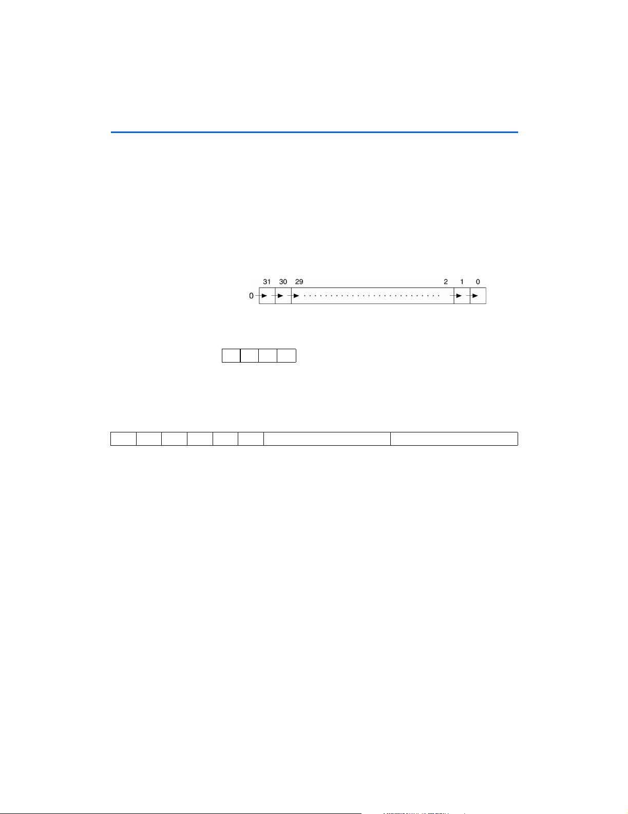
32-Bit Instruction Set
LSRI
Logical Shift Right Immediate
Operation:
Assembler Syntax: LSRI %rA,IMM5
Example: LSRI %g1,6 ; Right-shift %g1 by 6 bits
Description: The value in RA is shifted-right by the number of bits indicated by IMM5. The
Condition Codes: Flags: Unaffected
Instruction Format: Ri5
Instruction Fields: A = Register index of RA operand
1514131211109876543210
001001 IMM5 A
RA ← (RA >> IMM5), zero-fill from left
result is left-filled with zero.
NVZC
−−−−
IMM5 = 5-bit immediate value
66 Altera Corporation
Page 79
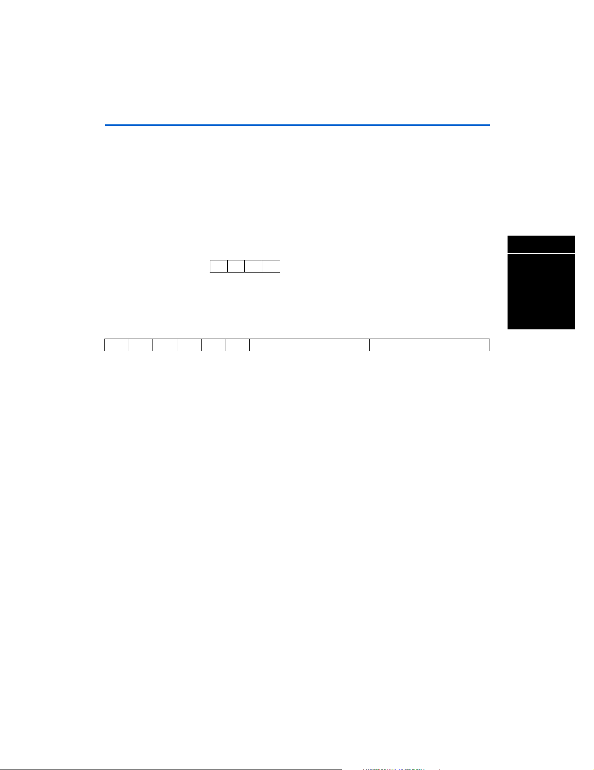
3232323232-Bit Instruction Set
MOV
Register-to-Register Move
Operation:
Assembler Syntax: MOV %rA,%rB
Example: MOV %o0,%L3 ; copy %L3 into %o 0
Description: Copy the contents of RB to RA.
Condition Codes: Flags: Unaffected
Instruction Format: RR
Instruction Fields: A = Register index of RA operand
1514131211109876543210
001100 B A
RA ← RB
NVZC
−−−−
B = Register index of RB operand
2
32-Bit Instruction
Set
Altera Corporation 67
Page 80

32-Bit Instruction Set
MOVHI
Move Immediate Into High Half-Word
h1
Operation:
Assembler Syntax: MOVHI %rA,IMM5
Example: Not preceded by PFX:
Description: Not preceded by PFX:
Condition Codes: Flags: Unaffected
RA ← (K : IMM5), h0RA unaffected
MOVHI %g3,23 ; upper 16 bits of %g 3 get 23
Preceded by PFX:
PFX %hi(100)
MOVHI %g3,%lo(100) ; upper 16 bits of %g3 get 100
Copy IMM5 to the most significant half-word (bits 31..16) of RA. The least
significant half-word (bits 15..0) is unaffected.
Preceded by PFX:
The immediate operand is extended from 5 to 16 bits by concatenating the
contents of the K-register (11 bits) with IMM5 (5 bits). The 16-bit immediate value
(K : IMM5) is copied into the most significant half-word (bits 31..16) of RA. The
least significant half-word (bits 15..0) is unaffected.
NVZC
−−−−
Instruction Format: Ri5
Instruction Fields: A = Register index of operand RA
IMM5 = 5-bit immediate value
1514131211109876543210
011011 IMM5 A
68 Altera Corporation
Page 81
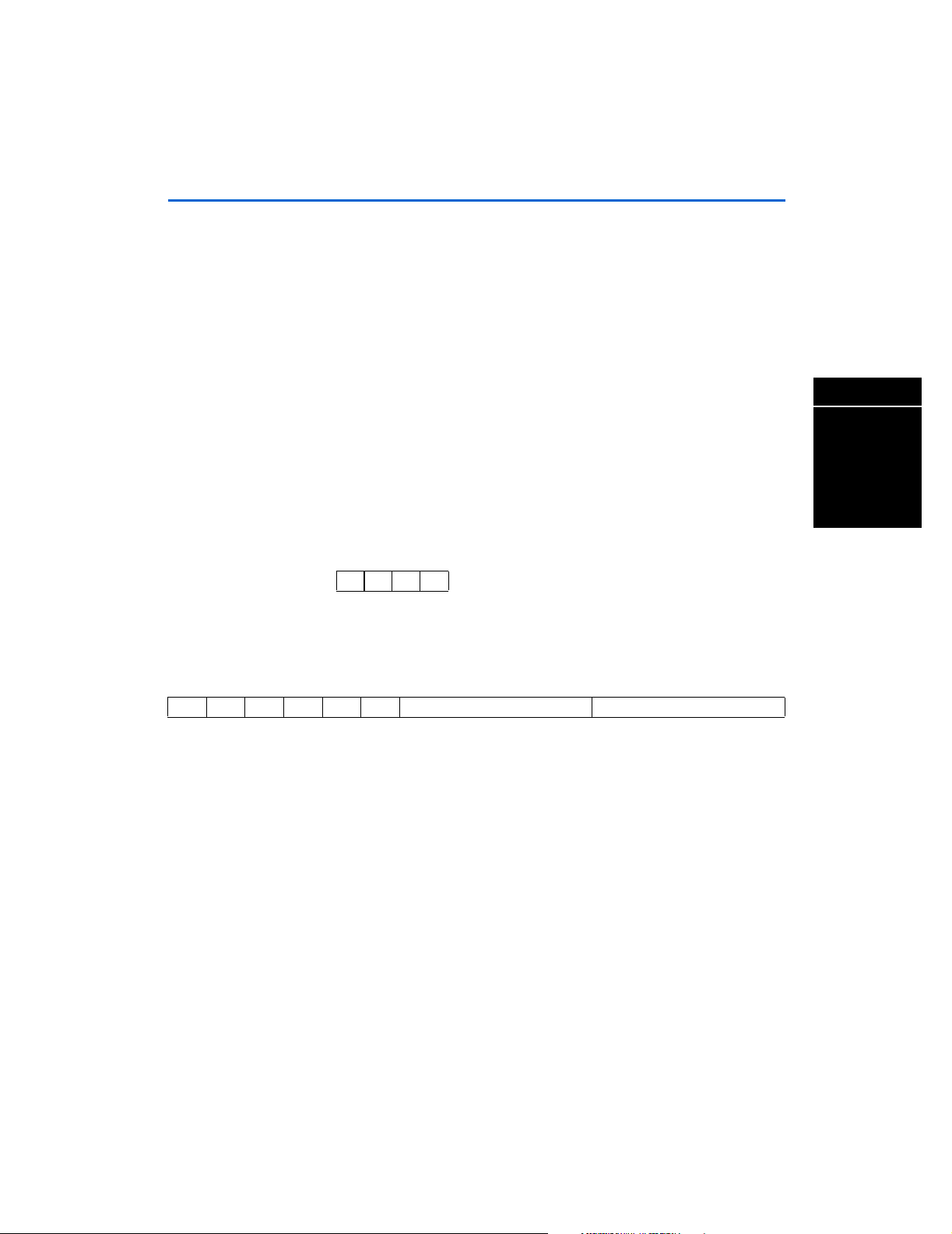
3232323232-Bit Instruction Set
MOVI
Move Immediate
Operation:
Assembler Syntax: MOVI %rA,IMM5
Example: Not preceded by PFX:
Description: Not preceded by PFX:
Condition Codes: Flags: Unaffected
Instruction Format: Ri5
Instruction Fields: A = Register index of RA operand
1514131211109876543210
001101 IMM5 A
RA ← (0x00.00 : K : IMM5)
MOVI %o3,7 ; load %o3 with 7
Preceded by PFX:
PFX %hi(301)
MOVI %o3,%lo(301) ; load %o3 with 301
Loads register RA with a zero-extended 5-bit immediate value (in the range
[0..31]) given by IMM5.
Preceded by PFX:
Loads register RA with a zero-extended 16-bit immediate value (in the range
[0..65535]) given by (K : IMM5).
NVZC
−−−−
IMM5 = 5-bit immediate value
2
32-Bit Instruction
Set
Altera Corporation 69
Page 82

32-Bit Instruction Set
MSTEP
Multiply-Step
Operation:
Assembler Syntax: MSTEP %rA
Example: MSTEP %g1 ; accumulate partial-product
Description: Implements a single step of an unsigned multiply. The multiplier in %r0 and
Condition Codes: Flags: Unaffected
Instruction Format: Rw
Instruction Fields: A = Register index of operand RA
1514131211109876543210
01111110100 A
If (R0[31] = = 1)
then R0 ← (R0 << 1) + RA
else R0 ← (R0 << 1)
multiplicand in RA. Result is accumulated into %r0. RA is not affected.
The following code fragment implements a 16-bit × 16-bit into 32-bit multiply. On
entry, %r0 and %r1 contain the multiplier and multiplicand, respectively. The
result is left in %r0.
SWAP %r0 ; Move multiplier into p lace
MSTEP %r1
MSTEP %r1
MSTEP %r1
… A total of 16 MSTEPs …
MSTEP %r1
; 32-bit product left in %r0
NVZC
−−−−
70 Altera Corporation
Page 83

3232323232-Bit Instruction Set
MUL
Multiply
Operation: R0 ← (R0 & 0x0000.ffff) x (RA & 0x0000.ffff)
Assembler Syntax: MUL %rA
Example: MUL %i5
Description: Multiply the low half-words of %r0 and %rA together, and put the 32 bit result into
%r0. This performs an integer multiplication of two signed 16-bit numbers to
produce a 32-bit signed result, or multiplication of two unsigned 16-bit numbers
to produce an unsigned 32-bit result.
Condition Codes: Flags: Unaffected
NVZC
−−−−
Instruction Format: Rw
Instruction Fields: A = Register index of operand RA
1514131211109876543210
01111110101 A
2
32-Bit Instruction
Set
Altera Corporation 71
Page 84

32-Bit Instruction Set
NEG
Arithmetic Negation
Operation:
Assembler Syntax: NEG %rA
Example: NEG %o4
Description: Negate the value of RA. Perform two’s complement negation of RA.
Condition Codes: Flags: Unaffected
Instruction Format: Rw
Instruction Fields: A = Register index of operand RA
1514131211109876543210
011111 00001 A
RA ← 0 – RA
NVZC
−−−−
72 Altera Corporation
Page 85

Operation: None
Assembler Syntax: NOP
Example: NOP ; do nothing
Description: No operation.
Condition Codes: Flags: Unaffected
NVZC
−−−−
3232323232-Bit Instruction Set
NOP
Equivalent to MOV %g0, %g0
2
32-Bit Instruction
Instruction Format: RR
Instruction Fields: None
1514131211109876543210
0011000000000000
Set
Altera Corporation 73
Page 86

32-Bit Instruction Set
NOT
Logical Not
Operation:
Assembler Syntax: NOT %rA
Example: NOT %o4
Description: Bitwise-invert the value of RA.
Condition Codes: Flags: Unaffected
Instruction Format: Rw
Instruction Fields: A = Register index of operand RA
1514131211109876543210
01111100000 A
RA ← ~RA
NVZC
−−−−
74 Altera Corporation
Page 87

Operation: Not preceded by PFX:
RA ← RA | RB
Preceded by PFX:
RA ← RA | (0x00.00 : K : IMM5)
Assembler Syntax: Not preceded by PFX:
OR %rA,%rB
Preceded by PFX:
PFX %hi(const)
OR %ra,%lo(const)
Example: Not preceded by PFX:
OR %i0,%i1 ; OR %i1 into %i0
Preceded by PFX:
PFX %hi(3333)
OR %i0,%lo(3333) ; OR %i0 with 333 3
Description: Not preceded by PFX:
Logically-OR the individual bits in RA with the corresponding bits in RB; store the
result in RA.
Preceded by PFX:
When prefixed, the RB operand is replaced by an immediate constant formed by
concatenating the contents of the K-register (11 bits) with IMM5 (5 bits). This
16-bit value is zero-extended to 32 bits, then bitwise-ORed with RA. The result is
written back into RA.
Condition Codes: Flags:
NVZC
∆ – ∆ –
N: Result bit 31
Z: Set if result is zero; cleared otherwise
Instruction Format: RR, Ri5
Instruction Fields A = Register index of operand RA
B = Register index of operand RB
IMM5 = 5-bit immediate value
3232323232-Bit Instruction Set
OR
Bitwise Logical OR
2
32-Bit Instruction
Set
Not preceded by PFX (RR)
1514131211109876543210
010000 B A
Preceded by PFX (Ri5)
15 14 13 12 11 10 9 8 7 6 5 4 3 2
010000 IMM5 A
Altera Corporation 75
10
Page 88

32-Bit Instruction Set
PFX
Prefix
Operation:
Assembler Syntax: PFX IMM11
Example: PFX 3 ; affects next instructi on
Description: Loads the 11-bit constant value IMM11 into the K-register. The value in the
Condition Codes: Flags: Unaffected
Instruction Format: i11
Instruction Fields: IMM11 = 11-bit immediate value
1514131211109876543210
10011 IMM11
K ← IMM11 (K set to zero by all other instructions)
K-register may affect the next instruction. K is set to zero after every instruction
other than PFX. The result of two consecutive PFX instructions is not defined.
NVZC
−−−−
76 Altera Corporation
Page 89

3232323232-Bit Instruction Set
RDCTL
Read Control Register
Operation:
Assembler Syntax: RDCTL %rA
Example: Not preceded by PFX:
Description: Not preceded by PFX:
Condition Codes: Flags: Unaffected
Instruction Format: Rw
Instruction Fields: A = Register index of operand RA
1514131211109876543210
011111 11001 A
RA ← CTLk
RDCTL %g7 ; Loads %g7 from STATUS reg (%ctl0)
Preceded by PFX:
PFX 2
RDCTL %g7 ; Loads %g7 from WVALID reg (%ctl2)
Loads RA with the current contents of the STATUS register (%ctl0).
Preceded by PFX:
Loads RA with the current contents of the control register selected by K. See
“Control Registers” on page 4. for a list of control registers and their indices.
NVZC
−−−−
2
32-Bit Instruction
Set
Altera Corporation 77
Page 90

32-Bit Instruction Set
RESTORE
Restore Caller’s Register Window
Operation:
Assembler Syntax: RESTORE
Example: RESTORE ; bump up the register window
Description: Moves CWP up by one position in the register file. If CWP is equal to HI_LIMIT
Condition Codes: Flags: Unaffected
Instruction Format: w
Instruction Fields: None
1514131211109876543210
0111110110100000
CWP ← CWP + 1
if (old-CWP = = HI_LIMIT)
then TRAP #2
(from the WVALID register) before the RESTORE instruction, then a windowoverflow trap (TRAP #2) is generated.
NVZC
−−−−
78 Altera Corporation
Page 91

3232323232-Bit Instruction Set
RET
Equivalent to JMP %i7
Operation:
Assembler Syntax: RET
Example: RET ; return
Description: Jump to the target-address given by (%i7 << 1). Note that the target address will
Condition Codes: Flags: Unaffected
Delay Slot Behavior: The instruction immediately following RET (RET’s delay slot) is executed after
Instruction Format: Rw
Instruction Fields: None (always uses %i7)
1514131211109876543210
0111111111011111
PC ← (%i7 << 1)
RESTORE ; (restores caller’s regis ter window)
always be half-word aligned for any value of %i7.
NVZC
−−−−
RET, but before the destination instruction. There are restrictions on which
instructions may be used as a delay slot (Refer to “Branch Delay Slots” on
page 23).
2
32-Bit Instruction
Set
Altera Corporation 79
Page 92

32-Bit Instruction Set
RLC
Rotate Left Through Carry
Operation:
Assembler Syntax: RLC %rA
Example: RLC %i4 ; rotate %i4 left one bit
Description: Rotates the bits of RA left by one position through the carry flag.
Condition Codes: Flags:
Instruction Format: Rw
Instruction Fields: A = Register index of operand RA
1514131211109876543210
01111100101 A
C ← RA[31]
RA ← (RA << 1) : C
NVZC
–––∆
C: Bit 31 of RA before rotating
80 Altera Corporation
Page 93

3232323232-Bit Instruction Set
RRC
Rotate Right Through Carry
Operation:
Assembler Syntax: RRC %rA
Example: RRC %i4 ; rotate %i4 right one bit
Description: Rotates the bits of RA right by one position through the carry flag.
If Preceded by PFX: Unaffected
Condition Codes: Flags:
Instruction Format: Rw
Instruction Fields: A = Register index of operand RA
1514131211109876543210
01111100110 A
C ← RA[0]
RA ← C:(RA>>1)
NVZC
–––∆
C: Bit 0 of RA before rotating
2
32-Bit Instruction
Set
Altera Corporation 81
Page 94

32-Bit Instruction Set
SAVE
Save Caller’s Register Window
Operation:
Assembler Syntax: SAVE %sp,-IMM8
Example: SAVE %sp,-23 ; start subroutin e with new regs
Description: Moves CWP down by one position in the register file. If CWP is equal to LO_LIMIT
Condition Codes: Flags: Unaffected
Instruction Format: i8v
Instruction Fields: IMM8 = 8-bit immediate value
1514131211109876543210
01111000 IMM8
CWP ← CWP – 1
%sp ← %fp – (IMM8 × 4)
If (old-CWP = = LO_LIMIT)
then TRAP #1
; first operand can only be %sp
(from the WVALID register) before the SAVE instruction, then a windowunderflow trap (TRAP #1) is generated.
%sp (in the newly opened register window) is loaded with the value of %fp minus
IMM8 times 4. %fp in the new window is the same as %sp in the old (caller’s)
window.
SAVE is conventionally used upon entry to subroutines to open up a new,
disposable set of registers for the subroutine and simultaneously open up a stackframe.
NVZC
−−−−
82 Altera Corporation
Page 95

3232323232-Bit Instruction Set
SEXT16
Sign Extend 16-bit Value
h0
Operation:
Assembler Syntax: SEXT16 %rA
Example: SEXT16 %g3 ; convert signed short to signe d long
Description: Replace bits 16..31 of RA with bit 15 of RA.
Condition Codes: Flags: Unaffected
RA ←σ(
NVZC
−−−−
RA)
2
32-Bit Instruction
Instruction Format: Rw
Instruction Fields: A = Register index of operand RA
1514131211109876543210
011111 00100 A
Set
Altera Corporation 83
Page 96

32-Bit Instruction Set
SEXT8
Sign Extend 8-bit Value
b0
Operation:
Assembler Syntax: SEXT8 %rA
Example: SEXT8 %o3 ; convert signed byte to signed long
Description: Replace bits 8..31 of RA with bit 7 of RA.
Condition Codes: Flags: Unaffected
Instruction Format: Rw
Instruction Fields: A = Register index of operand RA
1514131211109876543210
01111100011 A
RA ←σ(
NVZC
−−−−
RA)
84 Altera Corporation
Page 97

3232323232-Bit Instruction Set
SKP0
Skip If Register Bit Is 0
Operation:
Assembler Syntax: SKP0 %rA,IMM5
Example: ADDI %g0, 1 ; include if bit 7 was set
Description: Skip next instruction if the single bit RA[IMM5] is 0. If the next instruction is PFX,
Condition Codes: Flags: Unaffected
Instruction Format: Ri5
Instruction Fields: A = Register index of operand RA
1514131211109876543210
010100 IMM5 A
if (RA[IMM5] = = 0)
then begin
if (Mem16[PC + 2] is PFX)
then PC ← PC + 6
else PC ← PC + 4
end
then both PFX and the instruction following PFX are skipped together.
NVZC
−−−−
IMM5 = 5-bit immediate value
2
32-Bit Instruction
Set
Altera Corporation 85
Page 98

32-Bit Instruction Set
SKP1
Skip If Register Bit Is 1
Operation:
Assembler Syntax: SKP1 %rA,IMM5
Example: SKP1 %o3,21 ; skip if 21st bit of %o3 is s et
Description: Skip next instruction if the single bit RA[IMM5] is 1. If the next instruction is PFX,
Condition Codes: Flags: Unaffected
Instruction Format: Ri5
Instruction Fields: A = Register index of operand RA
1514131211109876543210
010101 IMM5 A
if (RA[IMM5] = = 1)
then begin
if (Mem16[PC + 2] is PFX)
then PC ← PC + 6
else PC ← PC + 4
end
ADDI %g0, 1 ; increment if 21st bit clear
then both PFX and the instruction following PFX are skipped together.
NVZC
−−−−
IMM5 = 5-bit immediate value
86 Altera Corporation
Page 99

3232323232-Bit Instruction Set
SKPRnz
Skip If Register Not Equal To 0
Operation:
Assembler Syntax: SKPRnz %rA
Example: SKPRnz %g3
Description: Skip next instruction if RA is not zero. If the next instruction is PFX, then both PFX
Condition Codes: Flags: Unaffected
Instruction Format: Rw
Instruction Fields: A = Register index of operand RA
1514131211109876543210
011111 11010 A
if (RA ! = 0)
then begin
if (Mem16[PC + 2] is PFX)
then PC ← PC + 6
else PC ← PC + 4
end
BSR SendIt ; only call if %g3 is z ero
NOP ; (delay slot) executed in eit her case
and the instruction following PFX are skipped together.
NVZC
−−−−
2
32-Bit Instruction
Set
Altera Corporation 87
Page 100

32-Bit Instruction Set
SKPRz
Skip If Register Equals 0
Operation:
Assembler Syntax: SKPRz %rA
Example: SKPRz %o3
Description: Skip next instruction if RA is equal to zero. If the next instruction is PFX, then both
Condition Codes: Flags: Unaffected
Instruction Format: Rw
Instruction Fields: A = Register index of operand RA
1514131211109876543210
0111111 0110 A
if (RA==0)
then begin
if (Mem16[PC + 2] is PFX)
then PC ← PC + 6
else PC ← PC + 4
end
BSR SendIt ; only call if %o3 is n ot 0
NOP ; (delay slot) executed in eit her case
PFX and the instruction following PFX are skipped together.
NVZC
−−−−
88 Altera Corporation
 Loading...