

Exar XRA1403IL24-F, XRA1403IG24-F, XRA1403IL24-0B-EB, XRA1403IG24-0B-EB, XRA1405IL24-F User Manual
...
REV. 1.0.0 XRA1403/1405 EVALUATION BOARD USER’S MANUAL
INTRODUCTION
This user’s manual is for the XRA1403/1405 16-bit evaluation board. Table 1 shows the different devices and
packages that the evaluation board supports. This user’s manual will describe the hardware setup required to
operate the different packages.
1.0 QUICK START
To verify communication with the GPIO expander, the following steps are recommended:
1.1 Connect external +5V power supply to J8 pin 1
1.2 Connect J12 pin 13 and 14 to ground of external power supply
1.3 Connect to MCU SPI interface for:
SPI clock (SCK_SCL signal at J5 pin11)
SO (SO_SPI signal at J5 pin17)
SI (SI_SPI signal at J5 pin21)
CS# (CS#_SPI signal at J5 pin19)
1.4 From the MCU, write the following registers:
GCR1 = 0x00
GCR2 = 0x00
If the LEDs turn on, the communication with the GPIO expander is successful.
To disable connection to LEDs, remove jumpers on J28, J29, J30 and J31. Connect to external inputs or
outputs at J3 and J4.
2.0 HARDWARE SETUP
2.1 Packages description
The evaluation board supports all 4 packages of the XRA1403 and XRA1405. The ordering part number,
package and location on the board is shown below in Table 1. Table 2 lists the evaluation board ordering part
numbers.
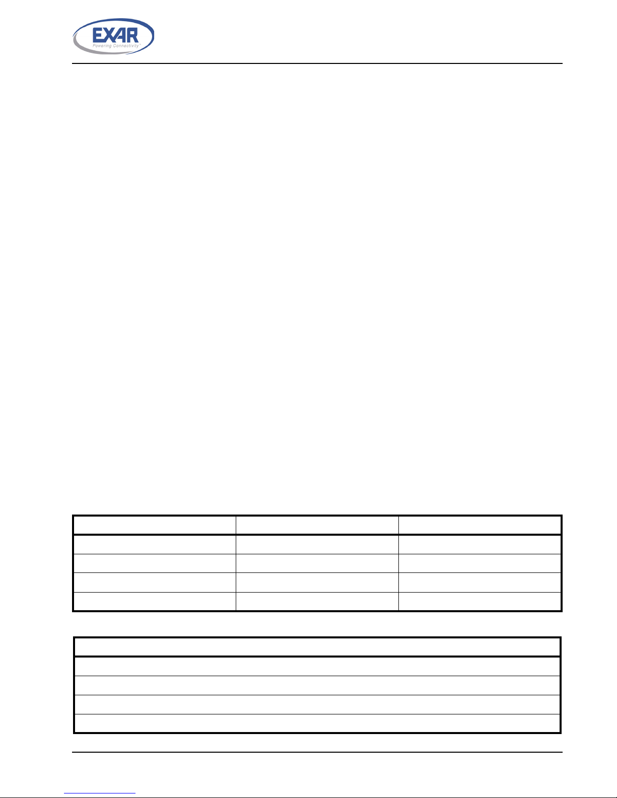
TABLE 1: PACKAGE LIST
ORDERING PART NUMBER PACKAGE LOCATION
XRA1403IL24-F 24-pin QFN U4
XRA1403IG24-F 24-pin TSSOP U5
XRA1405IL24-F 24-pin QFN U4
XRA1405IG24-F 24-pin TSSOP U5
TABLE 2: EVALUATION BOARD ORDERING PART NUMBERS
PART NUMBER
XRA1403IL24-0B-EB
XRA1403IG24-0B-EB
XRA1405IL24-0B-EB
XRA1405IG24-0B-EB
1
XRA1403/1405 EVALUATION BOARD USER’S MANUAL REV. 1.0.0
2.2 Jumper Settings
2.2.1 Common Jumpers
The following jumpers apply to all the 4 packages of XRA1403 and XRA1405:
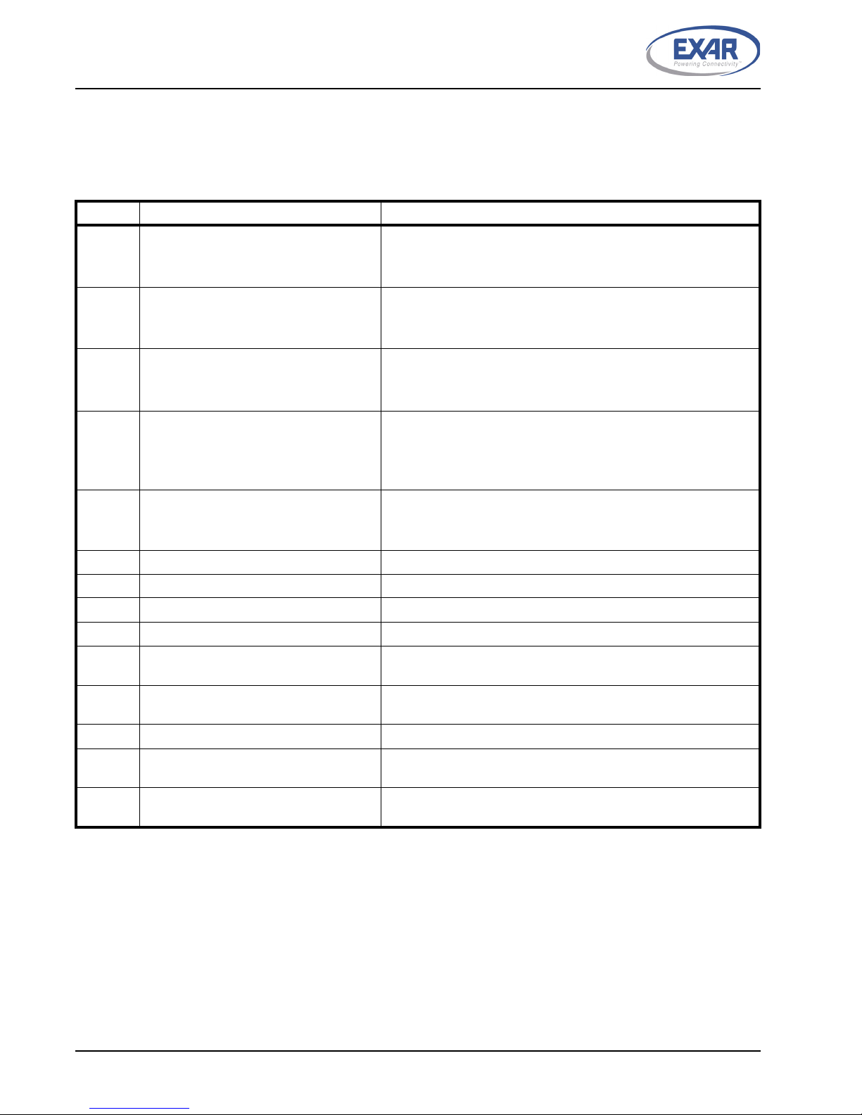
TABLE 3: COMMON JUMPER SETTINGS
JUMPERS FUNCTIONS COMMENTS
J8 Selects the supply voltage to generate
the +1.8V power supply for the board
1&2 selects +5V (default, Pin 1 -- Test point for external +5V)
2&3 selects +P
NOTE: Not installed. Trace between 1 & 2
J9 Selects the supply voltage to generate
the +2.5V power supply for the board
J13 Selects the supply voltage to generate
the +3.3V power supply for the board
J10 Selects the supply voltage for +VDDP Used only for the XRA1405
J11 Selects the supply voltage for +VDD Jumper in 1&2 selects +3.3V (default)
J12 Not used for XRA140x Installed but not used
J14 Not used for XRA140x Installed but not used
J6 Not used Installed but not used
J27 LEDs
J3 Header for testing GPIO[15:8] of both
TSSOP and QFN package
J4 Header for testing GPIO[7:0] of both
TSSOP and QFN package
J2 Header for internal test Not installed
J5 Header for XRA1403 and XRA1405 sig-
nals and spare signals
J7 Header for UART signals and spare sig-
nals
1&2 selects +5V (default)
2&3 selects +P
NOTE: Not installed. Trace between 1 & 2
1&2 selects +5V (default)
2&3 selects +P
NOTE: Not installed. Trace between 1 & 2
Jumper in 1&2 selects +3.3V
Jumper in 3&4 selects +2.5V
Jumper in 5&6 selects +1.8V
Jumper in 3&4 selects +2.5V
Jumper in 5&6 selects +1.8V
NOTE: Not installed. Pin 2 is connected to GND
Installed. Connect to external input/output.
Installed. Connect to external input/output. Remove jumpers on
J28, J29, J30 and J31 after test.
Installed. Connect SPI signals from this header to MCU.
Not installed. Some GPIO signals and spare signals are accessible at this header
2
REV. 1.0.0 XRA1403/1405 EVALUATION BOARD USER’S MANUAL
2.2.2 XRA1403IL24-F
The following jumpers apply to the XRA1403IL24-F:
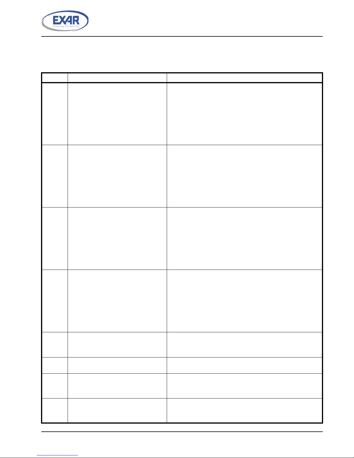
TABLE 4: JUMPER SETTINGS FOR XRA1403IL24-F
JUMPERS FUNCTIONS COMMENTS
J28 Header for connecting GPIO[7:0] signals
of QFN package
J29 Header for connecting GPIO[7:0] signals
of TSSOP package to LEDs
J30 Header for connecting GPIO[15:8] signals
of TSSOP package to LEDs
J31 Header for connecting GPIO[15:8] signals
of QFN package
J81 Selects the supply voltage for +VDD for
24-pin QFN packages
J82 Selects the corresponding signal for pin
18 of 24-pin QFN package
Jumper in pin 1 & J29 pin1 connects GPIO0 to LED
Jumper in pin 2 & J29 pin 3 connects GPIO1 to LED
Jumper in pin 3 & J29 pin 5 connects GPIO2 to LED
Jumper in pin 4 & J29 pin 7 connects GPIO3 to LED
Jumper in pin 5 & J29 pin 9 connects GPIO4 to LED
Jumper in pin 6 & J29 pin 11 connects GPIO5 to LED
Jumper in pin 7 & J29 pin 13 connects GPIO6 to LED
Jumper in pin 8 & J29 pin 15 connects GPIO7 to LED
1&2 connects GPIO0 to LED - 0 ohm resistor on board
3&4 connects GPIO1 to LED - 0 ohm resistor on board
5&6 connects GPIO2 to LED - 0 ohm resistor on board
7&8 connects GPIO3 to LED - 0 ohm resistor on board
9&10 connects GPIO4 to LED - 0 ohm resistor on board
11&12 connects GPIO5 to LED - 0 ohm resistor on board
13&14 connects GPIO6 to LED - 0 ohm resistor on board
15&16 connects GPIO7 to LED - 0 ohm resistor on board
1&2 connects GPIO8 to LED - 0 ohm resistor on board
3&4 connects GPIO9 to LED - 0 ohm resistor on board
5&6 connects GPIO10 to LED - 0 ohm resistor on board
7&8 connects GPIO11 to LED - 0 ohm resistor on board
9&10 connects GPIO12 to LED - 0 ohm resistor on board
11&12 connects GPIO13 to LED - 0 ohm resistor on board
13&14 connects GPIO14 to LED - 0 ohm resistor on board
15&16 connects GPIO15 to LED - 0 ohm resistor on board
Jumper in pin 1 & J30 pin 1 connects GPIO8 to LED
Jumper in pin 2 & J30 pin 3 connects GPIO9 to LED
Jumper in pin 3 & J30 pin 5 connects GPIO10 to LED
Jumper in pin 4 & J30 pin 7 connects GPIO11 to LED
Jumper in pin 5 & J30 pin 9 connects GPIO12 to LED
Jumper in pin 6 & J30 pin 11 connects GPIO13 to LED
Jumper in pin 7 & J30 pin 13 connects GPIO14 to LED
Jumper in pin 8 & J30 pin 15 connects GPIO15 to LED
Jumper in 2&4 selects +VDD (default)
Jumper in 1&3 selects +VDD
Jumper in 3&5 selects +VDD
NOTE: Use J87 pin 2 & 3
J83 Selects the corresponding signal for pin
23 of 24-pin QFN package
J84 Selects the corresponding signal for pin
24 of 24-pin QFN package
Jumper in 2&4 selects SI signal (default)
Jumper in 1&3 selects A1 signal
Jumper in 3&5 selects A1 signal
Jumper in 2&4 selects RESET# signal (default)
Jumper in 1&3 selects A2 signal
Jumper in 3&5 selects RESET# signal
3
 Loading...