

Exar XR77XXEVB-XCM-V80 User Manual
XXRR7777XXXXEEVVBB--XXCCMM--VV8800
ee
April 2016
Rev. 1.0.0
GENERAL DESCRIPTION
The XR77XXEVB-XCM-V80 (Exar Configuration
Module or XCM) is a board that is designed to
act as a USB to I
between a PC running PowerArchitect
configuration and design software and one of
Exar’s Universal PMICs. The PMIC can either
be on an Exar evaluation board or on a
customer board. On the right opposite side of
the XCM is a 10-pin connector which is used to
connect to the user’s system board in order to
communicate to any of the supported PMICs.
The XCM includes a µC with on-board flash so
that when powered from the system board, it
can act as a boot loader without the need to
have a PC connected.
This board is compatible with: XR77103,
XRP7704, XRP7708, XRP7740, XRP7713, and
XRP7714.
2
C bridge for communication
TM
4
XXRR7777XXXX CCoonnffiigguurraattiioonn MMoodduul
EEVVAALLUUAATTIIOONN BBOOAARRDD MMAANNUUAALL
FEATURES
• USB to I2C Communication for
Programmable PMIC Devices
• Boot Loader Functionality
− Avoids programming the NVM until final
configuration known
l
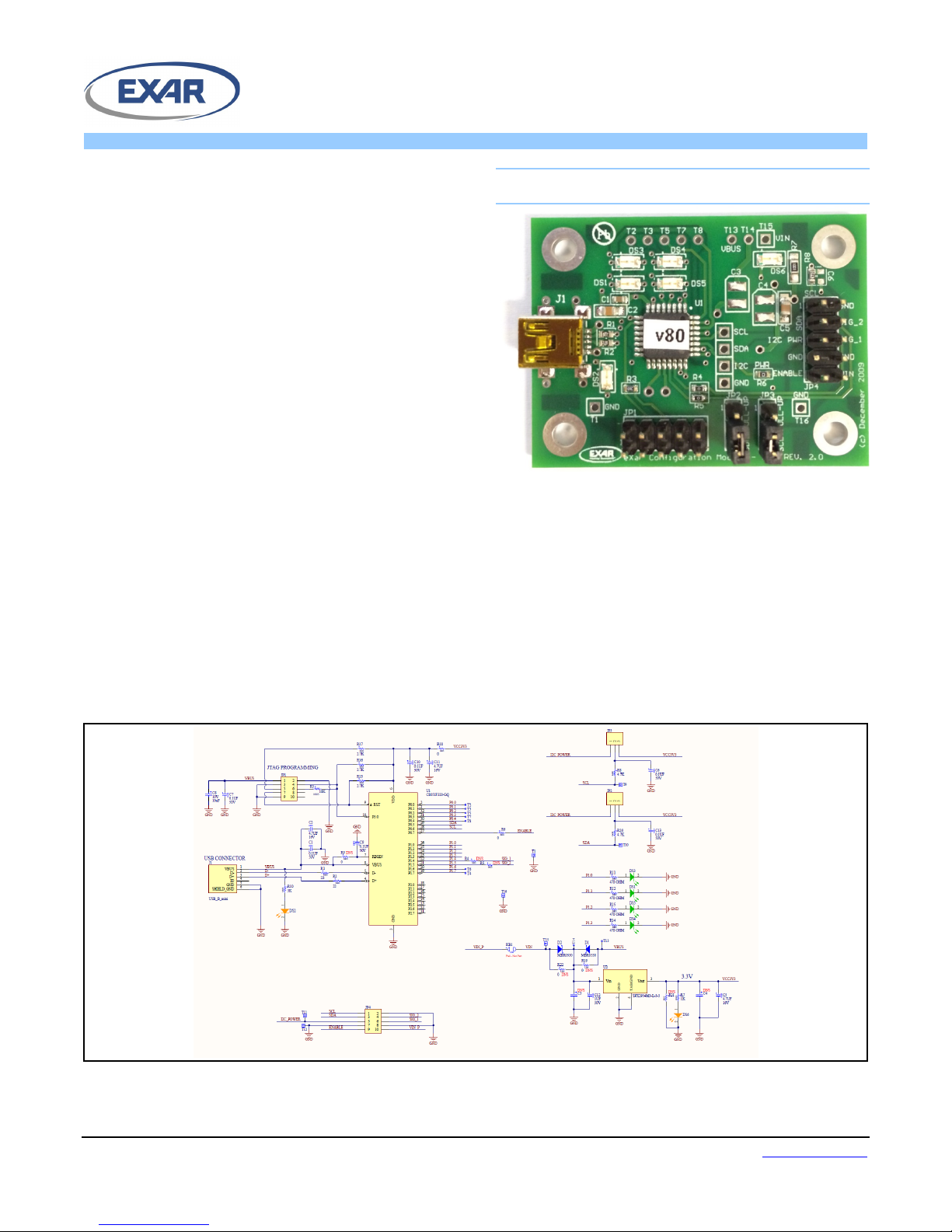
EVALUATION BOARD SCHEMATICS
Figure 1: XR77XXEVB-XCM-V80 Evaluation Board Schematics
• Powered by USB or System Board
• Enables Rapid Prototyping
Exar Corporation www.exar.com
48720 Kato Road, Fremont CA 94538, USA Tel. +1 510 668-7000 – Fax. +1 510 668-7001
XXRR7777XXXXEEVVBB--XXCCMM--VV8800
ee
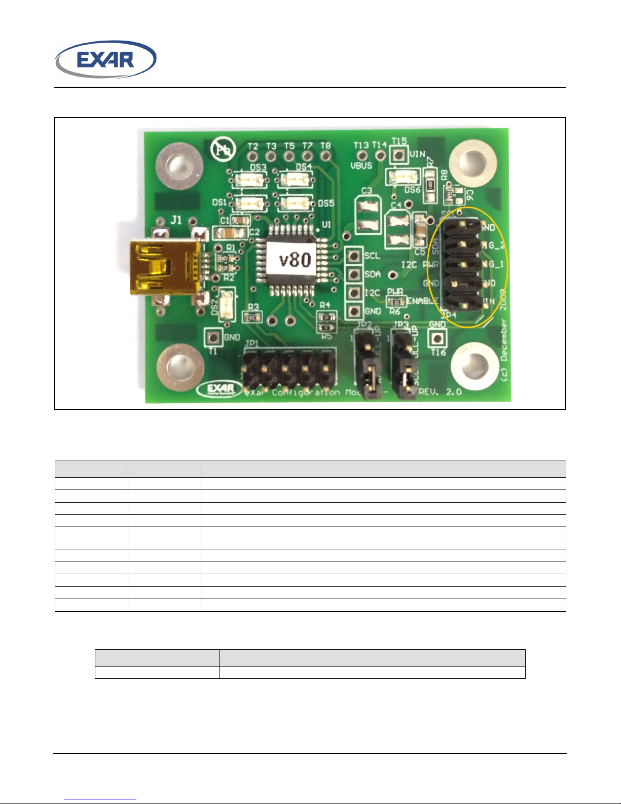
SCL
I2C Clock
GND
JP4 PIN2
Ground
SDA
JP4 PIN3
I2C Data
Sig_2
JP4 PIN4
General purpose signal 2
Sig_1
JP4 PIN6
General purpose signal 1
GND
Ground
GND
JP4 PIN8
Ground
ENABLE
JP4 PIN9
Connects to the EN pin of the XRP77XX. This is an input to the XCM board.
VIN
JP4 PIN10
Can connect to voltages from 4.5V to 30V
XR77XXEVB-XCM-V80
Exar Configuration Module for Power Architect 4 Support
PIN ASSIGNMENT
XXRR7777XXXX CCoonnffiigguurraattiioonn MMoodduul
l
Figure 2: XR77XXEVB-XCM-V80 JP4 Pin Assignment
PIN DESCRIPTION
Name Pin Number Description
JP4 PIN1
I2C Power
JP4 PIN5
JP4 PIN7
Connect to the preferred IO voltage. Only required when a voltage other than 3.3V is
desired.
ORDERING INFORMATION
Part Number Description
© 2016 Exar Corporation 2/9 Rev. 1.0.0
XXRR7777XXXXEEVVBB--XXCCMM--VV8800
ee
USING THE EVALUATION BOARD
XXRR7777XXXX CCoonnffiigguurraattiioonn MMoodduul
COMMUNICATION WITH THE XCM
l
O
PERATING ASSUMPTIONS
The following are the basic assumptions for
the operation of the XCM.
• Only one I
2
C Master is active at any time on
the customer board. The user must ensure
2
that only 1 master is active on the I
C lines
at the same time. This could entail Host in
Reset, Host communication lines disabled,
etc.
• The user must connect the appropriate
signals to from the system board to the
XCM JP4. At a minimum; SDA, SCL, and
GND must be connected.
• VIN and ENABLE must also be connected, if
the customer wants the XCM board to
operate in “Standalone Mode” (not
supported with XR77103).
2
Using I
C Communication
The XCM has an on board linear regulator to
provide power to the µC and provides power
to the I
2
C lines. The I2C bus pull-up resistors
are 4.7kohm. By changing the position of the
jumpers on JP2 and JP3, the pull-up resistors
can be connected to either the 3.3V provided
2
on the XCM or to the I
C Power connected to
JP4 Pin 5. In Figure 2 the jumpers are
configured to use the on board 3.3V. Moving
them to the other position connects the pull-
2
up resistors to the external I
C Power.
If the XCM is connected to the PC before
TM
starting the PowerArchitect
4 software, the
software should recognize the presence of the
board automatically. If the board is connected
after the software is started, the user will need
to click on “File”, then “Board Search” for the
software to find the board.
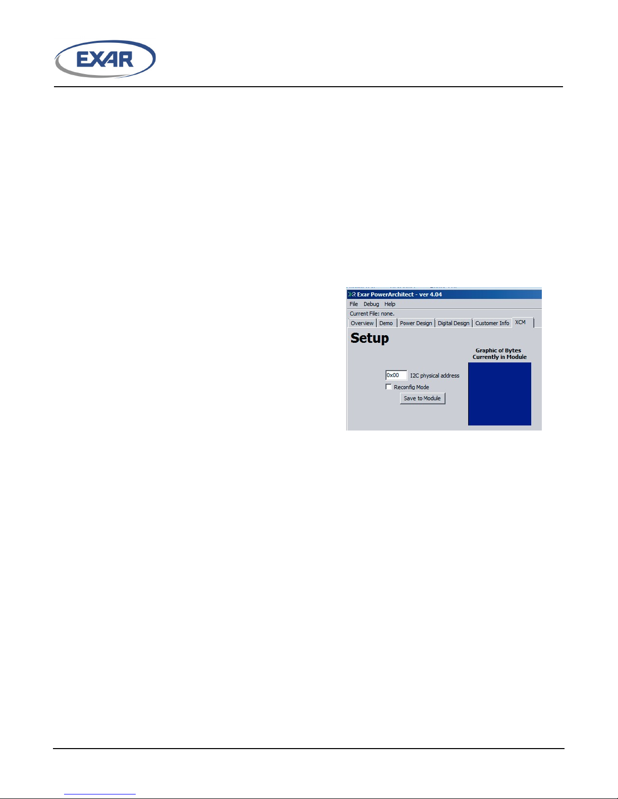
Once the board is identified, the software will
add a tab called “XCM” as shown in Figure 3.
This feature is not available for XR77103
device.
Figure 3: PowerArchitectTM 4 XCM Tab
LED INDICATORS:
There are 6 LEDs on the board.
There are four LEDs grouped in the upper left
hand corner of the board as shown in Figure 3.
IMPORTANT: When using the XCM with
XRP7713EVB or XRP7714EVB demo boards,
the jumpers should be configured to use the
3.3V provided on the XCM. When using with
the XR77103EVB board, the jumpers should
2
be removed since the I
C bus pull-up resistors
are installed on the XR77103EVB.
If the system board already has pull-up
resistors, then the jumpers can simply be
removed. This is the most likely scenario for
a system intended to interact with the
programmable features of the PMIC device on
the system board.
© 2016 Exar Corporation 3/9 Rev. 1.0.0
These are defined as:
DS3: USB Operation
GUI is communicating to XCM (solid on when
USB is connected)
DS4: Reconfig Mode
The XCM will boot load the supported device
with the stored configuration the ENABLE pin
transitions from Low to High (not available for
XR77103).
DS1: USB Activity
Flashes based upon the USB activity between
the XCM and the PC.
 Loading...